EP0752728A2 - Negative electrode material for use in lithium secondary batteries, its manufacture, and lithium secondary batteries incorporating this material - Google Patents
Negative electrode material for use in lithium secondary batteries, its manufacture, and lithium secondary batteries incorporating this material Download PDFInfo
- Publication number
- EP0752728A2 EP0752728A2 EP96401468A EP96401468A EP0752728A2 EP 0752728 A2 EP0752728 A2 EP 0752728A2 EP 96401468 A EP96401468 A EP 96401468A EP 96401468 A EP96401468 A EP 96401468A EP 0752728 A2 EP0752728 A2 EP 0752728A2
- Authority
- EP
- European Patent Office
- Prior art keywords
- lithium
- negative electrode
- lithium secondary
- secondary battery
- charge
- Prior art date
- Legal status (The legal status is an assumption and is not a legal conclusion. Google has not performed a legal analysis and makes no representation as to the accuracy of the status listed.)
- Granted
Links
Images







Classifications
-
- H—ELECTRICITY
- H01—ELECTRIC ELEMENTS
- H01M—PROCESSES OR MEANS, e.g. BATTERIES, FOR THE DIRECT CONVERSION OF CHEMICAL ENERGY INTO ELECTRICAL ENERGY
- H01M10/00—Secondary cells; Manufacture thereof
- H01M10/05—Accumulators with non-aqueous electrolyte
- H01M10/052—Li-accumulators
- H01M10/0525—Rocking-chair batteries, i.e. batteries with lithium insertion or intercalation in both electrodes; Lithium-ion batteries
-
- H—ELECTRICITY
- H01—ELECTRIC ELEMENTS
- H01M—PROCESSES OR MEANS, e.g. BATTERIES, FOR THE DIRECT CONVERSION OF CHEMICAL ENERGY INTO ELECTRICAL ENERGY
- H01M4/00—Electrodes
- H01M4/02—Electrodes composed of, or comprising, active material
- H01M4/36—Selection of substances as active materials, active masses, active liquids
- H01M4/58—Selection of substances as active materials, active masses, active liquids of inorganic compounds other than oxides or hydroxides, e.g. sulfides, selenides, tellurides, halogenides or LiCoFy; of polyanionic structures, e.g. phosphates, silicates or borates
- H01M4/581—Chalcogenides or intercalation compounds thereof
-
- H—ELECTRICITY
- H01—ELECTRIC ELEMENTS
- H01M—PROCESSES OR MEANS, e.g. BATTERIES, FOR THE DIRECT CONVERSION OF CHEMICAL ENERGY INTO ELECTRICAL ENERGY
- H01M4/00—Electrodes
- H01M4/02—Electrodes composed of, or comprising, active material
- H01M4/36—Selection of substances as active materials, active masses, active liquids
- H01M4/48—Selection of substances as active materials, active masses, active liquids of inorganic oxides or hydroxides
- H01M4/50—Selection of substances as active materials, active masses, active liquids of inorganic oxides or hydroxides of manganese
- H01M4/505—Selection of substances as active materials, active masses, active liquids of inorganic oxides or hydroxides of manganese of mixed oxides or hydroxides containing manganese for inserting or intercalating light metals, e.g. LiMn2O4 or LiMn2OxFy
-
- H—ELECTRICITY
- H01—ELECTRIC ELEMENTS
- H01M—PROCESSES OR MEANS, e.g. BATTERIES, FOR THE DIRECT CONVERSION OF CHEMICAL ENERGY INTO ELECTRICAL ENERGY
- H01M4/00—Electrodes
- H01M4/02—Electrodes composed of, or comprising, active material
- H01M4/36—Selection of substances as active materials, active masses, active liquids
- H01M4/48—Selection of substances as active materials, active masses, active liquids of inorganic oxides or hydroxides
- H01M4/52—Selection of substances as active materials, active masses, active liquids of inorganic oxides or hydroxides of nickel, cobalt or iron
- H01M4/525—Selection of substances as active materials, active masses, active liquids of inorganic oxides or hydroxides of nickel, cobalt or iron of mixed oxides or hydroxides containing iron, cobalt or nickel for inserting or intercalating light metals, e.g. LiNiO2, LiCoO2 or LiCoOxFy
-
- H—ELECTRICITY
- H01—ELECTRIC ELEMENTS
- H01M—PROCESSES OR MEANS, e.g. BATTERIES, FOR THE DIRECT CONVERSION OF CHEMICAL ENERGY INTO ELECTRICAL ENERGY
- H01M4/00—Electrodes
- H01M4/02—Electrodes composed of, or comprising, active material
- H01M4/36—Selection of substances as active materials, active masses, active liquids
- H01M4/58—Selection of substances as active materials, active masses, active liquids of inorganic compounds other than oxides or hydroxides, e.g. sulfides, selenides, tellurides, halogenides or LiCoFy; of polyanionic structures, e.g. phosphates, silicates or borates
- H01M4/5825—Oxygenated metallic salts or polyanionic structures, e.g. borates, phosphates, silicates, olivines
-
- Y—GENERAL TAGGING OF NEW TECHNOLOGICAL DEVELOPMENTS; GENERAL TAGGING OF CROSS-SECTIONAL TECHNOLOGIES SPANNING OVER SEVERAL SECTIONS OF THE IPC; TECHNICAL SUBJECTS COVERED BY FORMER USPC CROSS-REFERENCE ART COLLECTIONS [XRACs] AND DIGESTS
- Y02—TECHNOLOGIES OR APPLICATIONS FOR MITIGATION OR ADAPTATION AGAINST CLIMATE CHANGE
- Y02E—REDUCTION OF GREENHOUSE GAS [GHG] EMISSIONS, RELATED TO ENERGY GENERATION, TRANSMISSION OR DISTRIBUTION
- Y02E60/00—Enabling technologies; Technologies with a potential or indirect contribution to GHG emissions mitigation
- Y02E60/10—Energy storage using batteries
Definitions
- the present invention relates to lithium secondary batteries, negative electrode material for use in those batteries, and the methods of manufacture.
- a lithium secondary battery basically has a higher voltage and a higher energy density than other types of conventional secondary batteries, for example nickel cadmium batteries or lead storage batteries.
- the capacity per volume of negative electrode is around 2062 mAh/cm 3 .
- the cell is generally provided with an amount of lithium to give approximately three times the cell capacity to compensate for the abovementioned deterioration in the metallic lithium, the capacity per volume of negative electrode becomes 687 mAh/cm 3 .
- a material which utilizes a lithium intercalation reaction has gained attention.
- a carbonaceous material such as natural graphite or synthetic graphite, or an inorganic material such as di-niobium-penta-oxide (Nb 2 O 5 ), molybdenum dioxide (MoO 2 ), or titanium disulfide (TiS 2 ) have been investigated.
- the capacity per mass is relatively large at 370 mAh/g.
- the specific gravity of the carbonaceous material is low at 1.6 - 2.2 g/cm 3 , and if the electrode is made in sheet form, then this specific gravity reduces further to 1 - 1.5 g/cm 3 . Therefore, the capacity per negative electrode volume reduces to 370 - 555 mAh/cm 3 . This however is the theoretical value, and in practice is reduced even further to 200 - 370 mAh/cm 3 .
- the electrode potential at which the lithium ions can be stably inserted and extracted is high at 0.5 - 2.0V relative to a lithium reference electrode.
- the operating potential of the lithium secondary battery is reduced to 0.5 - 2.0V, and hence a high voltage cannot be attained.
- the electrochemical reaction for insertion and extraction of the lithium ions must be reversible.
- the inorganic material operates at low potentials of 0.0 - 1.5V
- the electrochemical reaction in the insertion and extraction of the lithium ions becomes non reversible, and the inorganic material is said to decompose.
- the inorganic material operates at low potentials of 0.0 - 1.5V relative to a lithium reference electrode.
- the crystalline Li 2.5 Co 0.5 N since the lithium is filled in the structure, then when this is used for the negative electrode of a lithium secondary battery, it is necessary to operate the cell so as to extract lithium ions from the negative electrode. That is, the cell must be operated from after discharging.
- the negative electrode material for use in lithium secondary batteries, of the present invention contains a negative electrode active material container made from an amorphous transition metal nitride containing lithium represented by the chemical formula Li 1+x M y N.
- M represents one or more elements selected from; a transition metal, group IIIA, group IVA, and group VA, and contains at least a transition metal, x is within the range from -0.2 - 2.0, and y is within the range from 0.1 - 0.6.
- the lithium secondary battery of the present invention is one which uses this novel negative electrode material.
- the problems with the abovementioned conventional technology are overcome, giving a battery of high energy density with large charge-discharge capacity, and a long cycle life.
- an amorphous transition metal nitride containing lithium represented by the chemical formula Li 1+x M y N (where M represents one or more elements selected from; a transition metal, group IIIA, group IVA, and group VA, and contains at least a transition metal, x is within the range from -0.2 - 2.0 and y is within the range from 0.1 - 0.6) is used for the negative electrode active material container. It is both novel and excellent.
- a negative electrode material having a negative electrode active material container made from an amorphous transition metal nitride containing lithium represented by the chemical formula Li 3-p-q M p N is both novel and excellent.
- M is one or more elements selected from; a transition metal, group IIIA, group IVA, and group VA, and contains at least a transition metal, p is within the range from 0.1 - 1.0, and q is within the range from 0.8 - 1.8.
- the lithium ions can be stably inserted and extracted in the region of low electrode potential below 1.5V relative to a lithium reference electrode (metallic lithium), and thus has a high capacity charge-discharge range.
- the transition metal represented by M or M' means an element in the periodic table; from Sc of atomic number 21 to Zn of atomic number 30, from Y of atomic number 39 to Cd of atomic number 48, or from La of atomic number 57 to Hg of atomic number 80.
- the group IIIA elements means the elements B, Al, Ga, In, Tl
- the group IVA elements means the elements C, Si, Ge, Sn, Pb
- the group VA elements means the elements P, As, Sb, Bi.
- LiMN (where M represents one or more elements selected from; a transition metal, group IIIA, group IVA, and group VA, and contains at least a transition metal) can be for example; LiCoN, LiNiN, LiCuN, LiCoFeN, LiCoNiN, LiCoCuN, LiNiCuN, LiCoAlN, LiCoGeN, or LiCoAsN.
- x is less than -0.2, then the Li 1+x M y N dissociates so that there is the possibility of being unable to effect charging-discharging. Moreover, if x is greater than 2.0, then the capacity of a cell using this as the negative electrode material drops. It is thus preferable for x to be within the range of -0.2 - 0.5, and ideally to be zero.
- y is less than 0.1 the insulation properties increase, thus degrading the cell performance of a cell using this for the negative electrode material, and giving rise to the possibility of dissociation of the Li 1+x M y N.
- y is greater than 0.6, the solid-solubility of the transition metal element becomes difficult. It is thus more preferable for y to be less than 0.5.
- the compound represented by the chemical formula Li 1+x M y N (-0.2 ⁇ x ⁇ 2.0, 0.1 ⁇ y ⁇ 0.6) or Li 3-p-q M p N (0.1 ⁇ p ⁇ 1.0, 0.8 ⁇ q ⁇ 1.8), for example; Li 1+x Co y N, Li 1+x Ni y N, or Li 1+x Cu y N; or Li 1+x Co y' Ni y'' N, Li 1+x Co y' Cu y'' N, or Li 1+x Ni y' Cu y'' N (where 0.1 ⁇ y'+y'' ( y) ⁇ 0.6), being the negative electrode active material container of the present invention, is heretofore unknown, and exists in a new phase (referred to hereunder as a 7 phase).
- This 7 phase is one in which the lithium ions exist in a dissociated condition.
- ⁇ as an angle of diffraction, it has no diffraction peak within a range from 30° to 70° with 2 ⁇ , and is thus amorphous.
- This ⁇ phase allows the reversible extraction and insertion of the lithium ions, as well as having a high charge-discharge capacity.
- the amorphous Li 1+x M y N of the present invention is obtained by extracting the lithium ions from a transition metal nitride containing lithium, or by forming a thin film. Such a once amorphized Li 1+x M y N cannot be subsequently crystallized, even if a quantity containing lithium ions is added, and thus continues to retain the amorphous condition.
- the Li 1+x M y N of the present invention made by passing once thorough an amorphizing process has a completely different structure from a transition metal nitride containing crystalline lithium, even if it can be represented by the same chemical formula, for example crystalline Li 2.5-x Co 0.5 N (0 ⁇ x ⁇ 0.755), and has completely different characteristics on a macro scale.
- the charge-discharge capacity is remarkably increased by using the 7 phase having a high charge-discharge capacity, for charging-discharging. That is to say, in X-ray powder diffraction measurements with an angle of diffraction of 2 ⁇ , it has no diffraction peak from 30° to 70°, and is thus amorphous. Hence cell performance is improved.
- the charge-discharge capacity is large, and the specific gravity is the same as or higher than that of carbonaceous materials. Hence the charge-discharge capacity per negative electrode unit volume is also greater than that for the carbonaceous materials heretofore used for the negative electrode active material container.
- high voltage, high energy density can be achieved without a marked drop in cell operating voltage.
- amorphous transition metal nitride containing lithium of the present invention as the negative electrode active material container, then a lithium secondary battery with high energy density, a large charge - discharge capacity, and a long cycle life can be realized.
- a transition metal nitride containing lithium represented by the chemical formula Li 1+x M y N (where M is one or more elements selected from; a transition metal, group IIIA, group IVA, and group VA, and contains at least a transition metal, x is within the range from -0.2 - 2.0, and y is within the range from 0.1 - 0.6) and furthermore, when x+y ⁇ 2 is satisfied, is a shortage of lithium within the structure. Consequently, when this is used for the negative electrode of the lithium secondary battery, the lithium ions move in the direction for insertion into the negative electrode. That is, the cell can be operated from after charging.
- this can be combined with a positive electrode active material made from a transition metal oxide containing lithium and having a high voltage with an electrode potential relative to a lithium metal electrode above 3 volts. That is to say, this can be combined with a transition metal nitride containing lithium represented by the chemical formula Li 2 M'O 2 (where M' indicates an element of one type or two types belonging to the transition metals, and z is the range from 0.5 - 1.0) as the positive electrode active material. Consequently with the lithium secondary battery, a higher operating voltage, a large charge-discharge capacity, a high energy density, and a long cycle life can be obtained.
- the amorphous transition metal nitride containing lithium for the negative electrode active material container of the present invention is obtained for example by amorphizing a transition metal nitride containing lithium (referred to hereunder as a precursor), represented by the chemical formula Li 3-y M y N (where M represents one or more elements selected from; a transition metal, group IIIA, group IVA, and group VA, and contains at least a transition metal, and y is within the range from 0.1 - 0.6).
- a precursor represented by the chemical formula Li 3-y M y N (where M represents one or more elements selected from; a transition metal, group IIIA, group IVA, and group VA, and contains at least a transition metal, and y is within the range from 0.1 - 0.6).
- the amorphizing method may involve for example; a method wherein the lithium ions are dissociated from the precursor by a chemical reaction; a method wherein the lithium ions are dissociated from the precursor by an electrochemical reaction; or a method wherein an amorphous thin film is formed from the precursor by a sputtering method.
- the precursor can be synthesized using lithium (Li) or lithium nitride (Li 3 N) and a transition metal or a transition metal nitride as the initial raw materials, weighed and mixed in predetermined quantities so as to give a compounding ratio for a chemical formula Li 3-y M y N (where M indicates an element belonging to a transition metal, and y is a range from 0.1 - 0.6), and then baked in an atmosphere of nitrogen.
- the lithium ions are then dissociated from the precursor by a chemical reaction, or an electrochemical reaction, thus giving the amorphous form.
- amorphizing by means of a chemical reaction there is a method wherein a predetermined quantity of iodine (I 2 ) is dissolved in dehydrated acetonitrile, and the precursor then added thereto, mixed and filtered.
- I 2 iodine
- amorphizing by means of an electrochemical reaction there is a method by charge taking part in an oxidation-reduction system so as to dissociate lithium ions from a working electrode, wherein the precursor as a working electrode, the lithium metal as a counter electrode and a nonaqueous electrolyte containing a lithium salt as the electrolyte are used with a predetermined quantity of electricity.
- amorphizing using the sputtering method there is a method wherein a sintered body of the precursor is used as a target in a normal sputtering apparatus, and an amorphous thin film is formed thereon in an atmosphere of Ar gas.
- the negative electrode in the present invention can be made as a thin film.
- the cell can be made extremely thin by having the negative electrode in the form of a thin film.
- a lithium secondary battery can be formed for example on top of an integrated circuit, so that weight reduction, miniaturization and slimming of various electronic devices can be advanced to unprecedented levels.
- a negative electrode material containing a negative electrode active material container is used in the lithium secondary battery
- the active material container contained in the positive electrode material it is possible to use for example an oxide compound or a sulphide compound of a transition metal such as, titanium, molybdenum, tungsten, niobium, vanadium, manganese, iron, chrome, nickel, cobalt or the like containing lithium.
- the lithium secondary battery in which the negative electrode active material container is combined with a transition metal oxide containing lithium represented by the chemical formula Li z M'O 2 (where M' represents one element or two or more elements belonging to the transition metals, and z is the range from 0.5 - 1.0) as the positive electrode active material, then the lithium ions can be stably inserted and extracted within the voltage range of 2.5 - 4.2V, and can thus have a high capacity charge-discharge region. Now if z is less than 0.5, it becomes difficult to form the oxide compound, and similarly this is so if z is greater than 1.0.
- Li z M'O 2 where M' represents one element or two or more elements belonging to the transition metals, and z is the range from 0.5 - 1.0
- Li z M'O 2 those such as LiNiO 2 , LiCoO 2 , LiNi 0.5 Co 0.5 O 2 , Li 0.5 MnO 2 , Li 0.5 Ni 0.5 V 0.5 O 2 , Li 0.5 Co 0.5 V 0.5 O 4 , LiFeO 2 , and LiMnO 2 for which a high voltage with an electrode potential relative to a lithium metal electrode of more than 3V, and a high energy density can be expected, are well suited for the positive electrode active material.
- the transition metal oxide containing lithium represented by the chemical formula Li z M'O 2 (where M' indicates an element of one type or two types belonging to the transition metals, and z is the range from 0.5 - 1.0) being the positive electrode active material of the present invention, can be synthesized by a normal baking process, or a sputtering method in thin film formation technology.
- this can be synthesized by weighing lithium nitrate and nickel oxide according to the chemical formula, then mixing, and baking at 700°C in an atmosphere of oxygen.
- this can be synthesized using a sintered material with a composition of Li 0.5 MnO 2 as a target and forming a thin film thereon in an atmosphere of a mixture of Ar and O 2 gas, and then annealing the thin film in an atmosphere of oxygen at 700°C.
- a sulphide compound represented by the chemical formula Li w fe 2 (SO 4 ) 3 (0 ⁇ w ⁇ 2.0) is also excellent.
- the discharge energy is high and a cell of long cycle life is possible
- a nonaqueous electrolyte an electrolyte impregnated polymer matrix, a polymer electrolyte, a solid state electrolyte, or a molten salt electrolyte, are appropriate.
- the nonaqueous electrolyte is in general made from a solvent with a lithium salt dissolved therein.
- a solvent for the nonaqueous electrolyte at least one or more solvents selected from: an ester of chain structure such as ethylene carbonate (EC), propylene carbonate (PC), dimethyl carbonate (DMC), diethyl carbonate (DEC), methyl ethyl carbonate (MEC); a ⁇ -lactone such as ⁇ -butyrolactone; an ether of chain structure such as 1,2-dimethoxyethane (DME), 1,2-diethoxyethane (DEE), 1-ethoxy,2-methoxy ethane (EME); an ether of ring structure such as tetrahydrofuran; and a nitrile such as acetonitrile, can be used.
- an ester of chain structure such as ethylene carbonate (EC), propylene carbonate (PC), dimethyl carbonate (DMC), diethyl carbonate (DEC
- a mixture solvent of ethylene carbonate and an ester of chain structure for example dimethyl carbonate, diethyl carbonate, or methyl ethyl carbonate
- a mixture solvent of ethyl carbonate and an ether of chain structure for example 1,2-dimethoxyethane, 1,2-diethoxyethane, 1-ethoxy,2-methoxy ethane, particularly good cell characteristics are displayed.
- a lithium salt such as LiAsF 6 , LiBF 4 , LiPF 6 , LiAlCl 4 , LiClO 4 , LiCF 3 SO 3 , LiSbF 6 , LiSCN, LiCl, LiC 6 H 5 SO 3 , LiN(CF 3 SO 2 ), LiC(CF 3 SO 2 ) 3 , or C 4 F 9 SO 3 Li, or a mixture of these may be used.
- a system with a lithium salt such as LiCF 3 SO 3 dissolved in a polyetherized compound such as poly (ethylene oxide) or a system with above-mentioned nonaqueous electrolyte impregnated into a polymer latex may be used.
- a system such as an Li 2 S-SiS 2 -Li 3 PO 4 system or an Li 4 SiO 4 -Li 3 VO 4 system may be used.
- molten salt electrolyte for example an AlCl 3 -1-butyl-pyridinium chloride - LiCl system, or an AlCl 3 -1-ethyl-3-methyl-imidazolium chloride - LiCl system, may be used.
- FIG. 1 shows an example of a lithium secondary battery applicable to the present invention.
- a gasket 8 is provided inside a positive case 11, and a negative case 9 is fitted into the gasket 8.
- a negative electrode 2 is provided inside the negative case 9, and a positive electrode 12 is positioned opposite to the negative electrode 2.
- An electrolyte 3 is filled between the negative electrode 2 and the positive electrode 12, with a separator 4 disposed therein.
- the negative electrode active material container of the negative electrode 2 a substance containing for example LiCo 0.4 N is applicable.
- the active material container is made by mixing; the amorphous LiCo 0.4 N synthesized by the chemical reaction as mentioned above, acetylene black as a conductive agent, and polytetrafluoroethylene as a binder, in a ratio by weight of 90:7:3, and then rolling into a sheet, and punching to a diameter of 16mm.
- the negative electrode 2 is secured to the negative case 9 by covering with a collector body 13 made from Ni mesh which is spot welded to the negative case 9.
- a nonaqueous electrolyte is used. This has 1 mole/liter of LiClO 4 dissolved in a mixture solvent of EC and DEE (in a volumetric ratio of 1:1).
- the separator 4 is made from a perforated film of polypropylene or polyethylene.
- a lithium nickel compound oxide such as LiNiO 2 is used for the positive electrode active material of the positive electrode 12.
- This positive electrode is made by synthesizing LiNiO 2 (positive electrode active material) by a normal baking method, and then mixing this LiNiO 2 , acetylene black as a conductive agent, and polytetrafluoroethylene as a binder, in a ratio by weight of 90:7:3, and then rolling into a sheet, and punching to a diameter of 16mm.
- the positive electrode 12 is secured to the positive case 11 by covering with a collector body 7 made from Ti mesh which is spot welded to the inside of the positive case 11.
- the capacity of the negative electrode and the positive electrode are adjusted so as to be the same. Moreover, the volumes of the negative electrode and the positive electrode are made so that their sum is equal to the interior volume of the lithium secondary battery
- the gasket 8 is for maintaining electrical insulation between the negative case 9 and the positive case 12.
- the opening rim of the positive case 11 is bent inwards and crimped over to thereby close off and seal the contents inside the cell.
- FIG. 2 shows a diffraction pattern measured using an X-ray powder diffraction apparatus, of LiCo 0.4 N synthesized by a chemical reaction so as to give the amorphous form. Copper was used in the tube of the X-ray diffraction apparatus, and measurements were made at a tube voltage of 30kV and a tube current of 100mA.
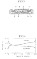
- FIG. 3 shows a test cell used in performance assessment of the negative electrode active material container of the lithium secondary battery according to the present invention.
- This test cell is an experimental type used for experiments on the negative electrode active material container, and as such is not a practical lithium secondary battery.
- negative electrode active material containers serving as experimental samples, were used as a working electrode 14.
- the respective materials were formed into the working electrode 14 by mixing with acetylene black as a conductive agent, and polytetrafluoroethylene as a binder, in a ratio by weight of 70 : 25 : 5, and then rolling into a sheet, and punching to a diameter of 16mm.
- the working electrode 14 was secured to a working electrode case 16 by covering with a net-like titanium collector body 15.
- the working electrode case 16 was made by press forming a stainless steel plate.
- a gasket 8 was provided inside the working electrode case 16, and a counter electrode case 17 fitted into the gasket 8.
- the counter electrode case 17 was also made by press forming a stainless steel plate.
- the gasket 8 maintained electrical insulation between the counter electrode case 17 and the working electrode case 16.
- a counter electrode 18 made from metallic lithium was provided inside the counter electrode case 17. With the counter electrode 18, a lithium metal foil of a predetermined thickness, punched to a diameter of 16mm, was bonded to the counter electrode case 17.
- a separator 4 made from a perforated film of polypropylene or polyethylene was located between the working electrode 14 and the counter electrode 18.
- a nonaqueous electrolyte 19 was filled between the working electrode 14 and the counter electrode 18.
- the nonaqueous electrolyte 19 had LiClO 4 dissolved as one mole/liter in a mixture solvent of a 1: 1 volume ratio of EC and DEE.
- the test cell was disassembled and the working electrode surface examined with a scanning electron microscope (SEM). However there was no evidence of lithium metal deposits or dendrite growth on the surface of the working electrode.
- SEM scanning electron microscope
- the working electrode was also analyzed with an X-ray diffraction apparatus, however no lithium metal X-ray diffraction pattern was found.
- test cell of example 3 was tested under charge-discharge conditions with a voltage range from 0.0 - 1.0V and a current of 1mA.
- the charge-discharge curve for the third cycle is shown in FIG. 5.
- the test cell On completion of the charge-discharge tests, the test cell was disassembled and the working electrode surface examined with an SEM. However there was no evidence of lithium metal deposits or dendrite growth on the surface of the working electrode.
- the working electrode was also analyzed with an X-ray diffraction apparatus, however no lithium metal X-ray diffraction pattern was found.
- the working electrode was made by mixing; the abovementioned amorphous LiCo 0.3 N synthesized by the electrochemical reaction, acetylene black as a conductive agent, and polytetrafluoroethylene as a binder, in a ratio by weight of 70:25:5, and then rolling into a sheet, and punching to a diameter of 16mm.
- components the same as for example 3 were used.
- the test cell On completion of the charge-discharge tests, the test cell was disassembled and the working electrode surface examined with an SEM. However there was no evidence of lithium metal deposits or dendrite growth on the working electrode surface.
- the working electrode was also analyzed with an X-ray diffraction apparatus, however no lithium metal X-ray diffraction pattern could be found.
- Tests were also made with the Li 1.2 Co 0.4 N substituted for the LiCo 0.4 N of the working electrode 14 of example 3.
- This working electrode was made by mixing; the abovementioned amorphous Li 1.2 Co 0.4 N synthesized by the electrochemical reaction, acetylene black as a conductive agent, and polytetrafluoroethylene as a binder, in a ratio by weight of 70:25:5, and then rolling into a sheet, and punching to a diameter of 16mm.
- components the same as for example 3 were used. Tests were made using this test cell under charge-discharge conditions with a voltage range from 0.0 - 1.4V and a current of 1mA.
- the test cell On completion of the charge-discharge tests, the test cell was disassembled and the working electrode surface examined with an SEM. However there was no evidence of lithium metal deposits or dendrite growth on the working electrode surface.
- the working electrode was also analyzed with an X-ray diffraction apparatus, however no lithium metal X-ray diffraction pattern could be found.
- the working electrode was made by mixing; the abovementioned amorphous LiNi 0.4 N synthesized by the chemical reaction, acetylene black as a conductive agent, and polytetrafluoroethylene as a binder, in a ratio by weight of 70:25:5, and then rolling into a sheet, and punching to a diameter of 16mm.
- components the same as for example 3 were used.
- Tests were made using this test cell under charge-discharge conditions with a voltage range from 0.0 - 1.2V and a current of 1mA.
- the charge-discharge curve for the third cycle is shown in FIG. 9.
- the test cell On completion of the charge-discharge tests, the test cell was disassembled and the working electrode surface examined with an SEM. However there was no evidence of lithium metal deposits or dendrite growth on the working electrode surface.
- the working electrode was also analyzed with an X-ray diffraction apparatus, however no lithium metal X-ray diffraction pattern could be found.
- LiCu 0.4 N synthesized by an electrochemical reaction so as to give the amorphous form
- a diffraction pattern was measured using an X-ray powder diffraction apparatus. Copper was used in the tube of the X-ray diffraction apparatus, and measurements were made at a tube voltage of 30kV and a tube current of 100mA.
- the working electrode was made by mixing; the abovementioned amorphous LiCu 0.4 N synthesized by the electrochemical reaction, acetylene black as a conductive agent, and polytetrafluoroethylene as a binder, in a ratio by weight of 70:25:5, and then rolling into a sheet, and punching to a diameter of 16mm.
- components the same as for example 3 were used.
- Tests were made using this test cell under charge-discharge conditions with a voltage range from 0.0 - 1.4V and a current of 1mA.
- the charge-discharge curve for the third cycle is shown in FIG. 11.
- the test cell On completion of the charge-discharge tests, the test cell was disassembled and the working electrode surface examined with an SEM. However there was no evidence of lithium metal deposits or dendrite growth on the working electrode surface.
- the working electrode was also analyzed with an X-ray diffraction apparatus, however no lithium metal X-ray diffraction pattern could be found.
- the working electrode was basically made as follows. A sintered body of chemical composition Li 2.6 Cu 0.4 N as a target, and a 16mm diameter stainless steel plate as a base plate, were arranged inside a standard high frequency sputtering apparatus. Then after evacuating the chamber, Ar gas was introduced, and the high frequency sputtering apparatus operated with a power of 200 watts and with the Ar gas atmosphere at a pressure of lPa, so that a thin film of amorphous Li 1.5 Cu 0.4 N was formed on the stainless base plate, giving the working electrode 14. The resultant thin film thickness was 5 microns. This working electrode 14 was then spot welded inside the working electrode case 16. Apart from the working electrode 14, components the same as for example 3 were used.
- Tests were made using this test cell under charge-discharge conditions with a voltage range from 0.0 - 1.4V and a current of 1mA. With this Li 1.5 Cu 0.4 N also, reversible insertion and extraction of the lithium ions was possible within the voltage range from 0.0 - 1.4V. Steady charging and discharging was repeated for more than 50 cycles without observing any accompanying sudden drop in capacity.
- the test cell On completion of the charge-discharge tests, the test cell was disassembled and the working electrode surface examined with an SEM. However there was no evidence of lithium metal deposits or dendrite growth on the working electrode surface.
- the working electrode was also analyzed with an X-ray diffraction apparatus, however no lithium metal X-ray diffraction pattern could be found.
- FIG. 13 shows the charge-discharge curve for the fifth cycle. As is clear from FIG. 13, a capacity of 45mAh was obtained
- This lithium secondary battery was subjected to extremely steady repeated charging and discharging, and a cycle life of 600 cycles obtained.
- the cell On completion of the charge-discharge tests, the cell was disassembled and the negative electrode surface examined with an SEM. However there was no evidence of lithium metal deposits or dendrite growth on the negative electrode surface.
- the negative electrode was also analyzed with an X-ray diffraction apparatus, however no lithium metal X-ray diffraction pattern could be found.
- LiNi 0.4 N was used for the negative electrode active material container of the negative electrode 2.
- This LiNi 0.4 N was the abovementioned amorphous LiNi 0.4 N synthesized by the chemical reaction.
- the method of manufacture of the negative electrode 2 was the same as for example 1, and apart from the negative electrode 2, components the same as for example 1 were used.
- charge-discharge tests were carried out with a voltage range from 2.5 - 4.2V and a current of 1mA.
- FIG. 14 shows the charge-discharge curve for the fifth cycle.
- the cell On completion of the charge-discharge tests, the cell was disassembled and the negative electrode surface examined with an SEM. However there was no evidence of lithium metal deposits or dendrite growth on the negative electrode surface.
- the negative electrode was also analyzed with an X-ray diffraction apparatus, however no lithium metal X-ray diffraction pattern could be found.
- LiCu 0.4 N was used for the negative electrode active material container of the negative electrode 2.
- This LiCu 0.4 N was the abovementioned amorphous LiCu 0.4 N synthesized by the electrochemical reaction.
- the method of manufacture of the negative electrode 2 was the same as for example 1, and apart from the negative electrode 2, components the same as for example 1 were used.
- charge-discharge tests were carried out with a voltage range from 2.5 - 4.2V and a current of 1mA.
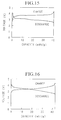
- FIG. 15 shows the charge-discharge curve for the fifth cycle.
- the cell On completion of the charge-discharge tests, the cell was disassembled and the negative electrode surface examined with an SEM. However there was no evidence of lithium metal deposits or dendrite growth on the negative electrode surface.
- the negative electrode was also analyzed with an X-ray diffraction apparatus, however no lithium metal X-ray diffraction pattern could be found.
- the cell On completion of the charge-discharge tests, the cell was disassembled and the negative electrode surface examined with an SEM. However there was no evidence of lithium metal deposits or dendrite growth on the negative electrode surface.
- the negative electrode was also analyzed with an X-ray diffraction apparatus, however no lithium metal X-ray diffraction pattern could be found.
- the cell On completion of the charge-discharge tests, the cell was disassembled and the negative electrode surface examined with an SEM. However there was no evidence of lithium metal deposits or dendrite growth on the negative electrode surface.
- the negative electrode was also analyzed with an X-ray diffraction apparatus, however no lithium metal X-ray diffraction pattern could be found.
- a nonaqueous electrolyte with the solute of the nonaqueous electrolyte 3 changed from LiClO 4 to LiPF 6 was used.
- the concentration of the solute was 1 mole/liter.
- components the same as for example 14 were used.
- charge-discharge tests were carried out with a voltage range from 2.5 - 4.2V and a current of 1mA.
- FIG. 17 shows the charge-discharge curve for the fifth cycle.
- the cell On completion of the charge-discharge tests, the cell was disassembled and the negative electrode surface examined with an SEM. However there was no evidence of lithium metal deposits or dendrite growth on the negative electrode surface.
- the negative electrode was also analyzed with an X-ray diffraction apparatus, however no lithium metal X-ray diffraction pattern could be found.
- the cell On completion of the charge-discharge tests, the cell was disassembled and the negative electrode surface examined with an SEM. However there was no evidence of lithium metal deposits or dendrite growth on the negative electrode surface.
- the negative electrode was also analyzed with an X-ray diffraction apparatus, however no lithium metal X-ray diffraction pattern could be found.
- the cell On completion of the charge-discharge tests, the cell was disassembled and the negative electrode surface examined with an SEM. However there was no evidence of lithium metal deposits or dendrite growth on the negative electrode surface.
- the negative electrode was also analyzed with an X-ray diffraction apparatus, however no lithium metal X-ray diffraction pattern could be found.
- a nonaqueous electrolyte with the solute of the nonaqueous electrolyte 3 changed from LiClO 4 to LiPF 6 was used.
- the concentration of the solute was 1 mole/liter.
- components the same as for example 17 were used.
- charge-discharge tests were carried out with a voltage range from 2.5 - 4.2V and a current of 1mA.
- the capacity of this lithium secondary battery under repeated steady charging and discharging was 40mAh.
- a cycle life of 550 cycles was obtained.
- the cell On completion of the charge-discharge tests, the cell was disassembled and the negative electrode surface examined with an SEM. However there was no evidence of lithium metal deposits or dendrite growth on the negative electrode surface.
- the negative electrode was also analyzed with an X-ray diffraction apparatus, however no lithium metal X-ray diffraction pattern could be found.
- the cell On completion of the charge-discharge tests, the cell was disassembled and the negative electrode surface examined with an SEM. However there was no evidence of lithium metal deposits or dendrite growth on the negative electrode surface.
- the negative electrode was also analyzed with an X-ray diffraction apparatus, however no lithium metal X-ray diffraction pattern could be found.
- a cell was made wherein the negative electrode active material container of the negative electrode 2 in the lithium secondary battery of example 1, was changed to natural graphite.
- the negative electrode 2 was made as follows. Polytetrafluoroethylene serving as a binder was mixed with standard natural graphite and the mixture then rolled into a sheet, and punched to a diameter of 16mm to from the negative electrode. The ratio by weight of negative electrode active material to binder was 95:5.
- the negative electrode 2 was secured to the negative case 9 by covering with a collector body 13 made from Ni mesh which was spot welded to the negative case 9. Apart from the negative electrode 2, construction was the same as for example 1.
- FIG. 19 shows the charge-discharge curve for the fifth cycle.
- This lithium secondary battery was subjected to extremely steady repeated charging and discharging, and a cycle life of 600 cycles obtained. However as is clear from FIG. 19, a capacity of only 30mAh was obtained.
- a lithium secondary battery was constructed having the same construction as the lithium secondary battery shown in FIG. 1 and described in example 1, except that lithium metal was used for the negative electrode. Charge-discharge tests were carried on this lithium secondary battery, with a voltage range from 2.5 - 4.2V and a current of 1mA.
- Table 1 shows the characteristics of the respective lithium secondary batteries of example 10 and control examples 1 and 2.
- the lithium secondary battery of the present invention provides both a large charge-discharge capacity and a long cycle life.
- the test cell On completion of the charge-discharge tests, the test cell was disassembled and the working electrode surface examined with an SEM. However there was no evidence of lithium metal deposits or dendrite growth on the working electrode surface.
- the working electrode was also analyzed with an X-ray diffraction apparatus, however no lithium metal X-ray diffraction pattern was found.
- the LiCo 0.5 N in example 20 was replaced by Li 1.15 Co 0.5 N synthesized by a chemical reaction so as to give the amorphous form.
- Charge-discharge tests were carried out with a voltage range from 0.0 - 1.3V and a current of 1mA.
- the charge-discharge curve for the second cycle is shown in FIG. 21.
- the test cell On completion of the charge-discharge tests, the test cell was disassembled and the working electrode surface examined with an SEM. However there was no evidence of lithium metal deposits or dendrite growth on the working electrode surface.
- the working electrode was also analyzed with an X-ray diffraction apparatus, however no lithium metal X-ray diffraction pattern could be found.
- a test cell was made with the LiCo 0.5 N in example 20 replaced by Li 1.24 Co 0.5 N synthesized by an electrochemical reaction so as to give the amorphous form. Tests were carried out under charge-discharge conditions with a voltage range from 0.0 - 1.2V and a current of 1mA. The charge-discharge curve for the second cycle is shown in FIG. 22.
- the test cell On completion of the charge-discharge tests, the test cell was disassembled and the working electrode surface examined with an SEM. However there was no evidence of lithium metal deposits or dendrite growth on the working electrode surface.
- the working electrode was also analyzed with an X-ray diffraction apparatus, however no lithium metal X-ray diffraction pattern could be found.
- a test cell was made with the LiCo 0.5 N in example 20 replaced by Li 1.05 Co 0.4 N synthesized by a chemical reaction so as to give the amorphous form. Tests were carried out under charge-discharge conditions with a voltage range from 0.0 - 1.2V and a current of 1mA. The charge-discharge curve for the second cycle is shown in FIG. 23.
- the test cell On completion of the charge-discharge tests, the test cell was disassembled and the working electrode surface examined with an SEM. However there was no evidence of lithium metal deposits or dendrite growth on the working electrode surface.
- the working electrode was also analyzed with an X-ray diffraction apparatus, however no lithium metal X-ray diffraction pattern could be found.
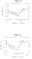
- a test cell was made with the LiCo 0.5 N in example 20 replaced by Li 0.96 Co 0.4 N synthesized by an electrochemical reaction so as to give the amorphous form. Tests were carried out under charge-discharge conditions with a voltage range from 0.0 - 1.4V and a current of 1mA. The charge-discharge curve for the second cycle is shown in FIG. 24.
- the test cell On completion of the charge-discharge tests, the test cell was disassembled and the working electrode surface examined with an SEM. However there was no evidence of lithium metal deposits or dendrite growth on the working electrode surface.
- the working electrode was also analyzed with an X-ray diffraction apparatus, however no lithium metal X-ray diffraction pattern could be found.
- a test cell was made with the LiCo 0.5 N in example 20 replaced by Li 0.95 Co 0.6 N synthesized by an electrochemical reaction so as to give the amorphous form. Tests were carried out under charge-discharge conditions with a voltage range from 0.0 - 1.4V and a current of 1mA. The charge-discharge curve for the second cycle is shown in FIG. 25.
- the test cell On completion of the charge-discharge tests, the test cell was disassembled and the working electrode surface examined with an SEM. However there was no evidence of lithium metal deposits or dendrite growth on the working electrode surface.
- the working electrode was also analyzed with an X-ray diffraction apparatus, however no lithium metal X-ray diffraction pattern could be found.
- a test cell was made with the LiCo 0.5 N in example 20 replaced by Li 1.5 Ni 0.5 N synthesized by an electrochemical reaction so as to give the amorphous form. Tests were carried out under the same charge-discharge conditions as for example 20. The charge-discharge curve for the second cycle is shown in FIG. 26.
- the test cell On completion of the charge-discharge tests, the test cell was disassembled and the working electrode surface examined with an SEM. However there was no evidence of lithium metal deposits or dendrite growth on the working electrode surface.
- the working electrode was also analyzed with an X-ray diffraction apparatus, however no lithium metal X-ray diffraction pattern could be found.
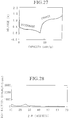
- a test cell was made with the LiCo 0.5 N in example 20 replaced by Li 1.09 Cu 0.4 N synthesized by an electrochemical reaction so as to give the amorphous form. Tests were carried out under the same charge-discharge conditions as for example 20. The charge-discharge curve for the second cycle is shown in FIG. 27.
- the test cell On completion of the charge-discharge tests, the test cell was disassembled and the working electrode surface examined with an SEM. However there was no evidence of lithium metal deposits or dendrite growth on the working electrode surface.
- the working electrode was also analyzed with an X-ray diffraction apparatus, however no lithium metal X-ray diffraction pattern could be found.
- the test cell On completion of the charge-discharge tests, the test cell was disassembled and the working electrode surface examined with an SEM. However there was no evidence of lithium metal deposits or dendrite growth on the working electrode surface.
- the working electrode was also analyzed with an X-ray diffraction apparatus, however no lithium metal X-ray diffraction pattern was found.
- FIG. 30 shows a diffraction pattern measured using an X-ray powder diffraction apparatus, of LiCo 0.4 Ni 0.1 N synthesized by a chemical reaction so as to give the amorphous form. Copper was used in the tube of the X-ray diffraction apparatus, and measurements were made at a tube voltage of 30kV and a tube current of 100mA.
- a test cell was then made with the LiCo 0.4 Fe 0.1 N in example 28 replaced by this LiCo 0.4 Ni 0.1 N, and tests were carried out under charge-discharge conditions with a voltage range from 0.0 - 1.4V and a current of 1mA.
- the charge-discharge curve for the fifth cycle is shown in FIG. 31.
- the test cell On completion of the charge-discharge tests, the test cell was disassembled and the working electrode surface examined with an SEM. However there was no evidence of lithium metal deposits or dendrite growth on the working electrode surface.
- the working electrode was also analyzed with an X-ray diffraction apparatus, however no lithium metal X-ray diffraction pattern could be found.
- a test cell was then made as before with the LiCo 0.4 Fe 0.1 N in example 28 replaced by this Li 1.1 Co 0.2 Ni 0.2 N, and tests were carried out under charge-discharge conditions with a voltage range from 0.0 - 1.3V and a current of 1mA.
- the test cell On completion of the charge-discharge tests, the test cell was disassembled and the working electrode surface examined with an SEM. However there was no evidence of lithium metal deposits or dendrite growth on the working electrode surface.
- the working electrode was also analyzed with an X-ray diffraction apparatus, however no lithium metal X-ray diffraction pattern could be found.
- a test cell was then made as before with the LiCo 0.4 Fe 0.1 N in example 28 replaced by this LiCo 0.4 Mn 0.1 N, and tests were carried out under charge-discharge conditions with a voltage range from 0.0 - 1.4V and a current of 1mA.
- the test cell On completion of the charge-discharge tests, the test cell was disassembled and the working electrode surface examined with an SEM. However there was no evidence of lithium metal deposits or dendrite growth on the working electrode surface.
- the working electrode was also analyzed with an X-ray diffraction apparatus, however no lithium metal X-ray diffraction pattern could be found.
- a test cell was then made as before with the LiCo 0.4 Fe 0.1 N in example 28 replaced by this LiCo 0.4 Cu 0.1 N, and tests were carried out under charge-discharge conditions with a voltage range from 0.0 - 1.4V and a current of 1mA.
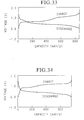
- the charge-discharge curve for the fifth cycle is shown in FIG. 33.
- the test cell On completion of the charge-discharge tests, the test cell was disassembled and the working electrode surface examined with an SEM. However there was no evidence of lithium metal deposits or dendrite growth on the working electrode surface.
- the working electrode was also analyzed with an X-ray diffraction apparatus, however no lithium metal X-ray diffraction pattern could be found.
- a test cell was then made as before with the LiCo 0.4 Fe 0.1 N in example 28 replaced by this LiCo 0.1 Cu 0.4 N, and tests were carried out under charge-discharge conditions with a voltage range from 0.0 - 1.4V and a current of 1mA.
- the charge-discharge curve for the fifth cycle is shown in FIG. 34.
- the test cell On completion of the charge-discharge tests, the test cell was disassembled and the working electrode surface examined with an SEM. However there was no evidence of lithium metal deposits or dendrite growth on the working electrode surface.
- the working electrode was also analyzed with an X-ray diffraction apparatus, however no lithium metal X-ray diffraction pattern could be found.
- a test cell was then made as before with the LiCo 0.4 Fe 0.1 N in example 28 replaced by this Li 1.2 Co 0.2 Cu 0.2 N, and tests were carried out under charge-discharge conditions with a voltage range from 0.0 - 1.2V and a current of 1mA.
- the test cell On completion of the charge-discharge tests, the test cell was disassembled and the working electrode surface examined with an SEM. However there was no evidence of lithium metal deposits or dendrite growth on the working electrode surface.
- the working electrode was also analyzed with an X-ray diffraction apparatus, however no lithium metal X-ray diffraction pattern could be found.
- LiCo 0.4 Zn 0.1 N synthesized by an electrochemical reaction so as to give the amorphous form
- a test cell was then made as before with the LiCo 0.4 Fe 0.1 N in example 28 replaced by this LiCo 0.4 Zn 0.1 N, and tests were carried out under charge-discharge conditions with a voltage range from 0.0 - 1.4V and a current of 1mA.
- the test cell On completion of the charge-discharge tests, the test cell was disassembled and the working electrode surface examined with an SEM. However there was no evidence of lithium metal deposits or dendrite growth on the working electrode surface.
- the working electrode was also analyzed with an X-ray diffraction apparatus, however no lithium metal X-ray diffraction pattern could be found.
- LiNi 0.4 Fe 0.1 N synthesized by an electrochemical reaction so as to give the amorphous form
- a test cell was then made as before with the LiCo 0.4 Fe 0.1 N in example 28 replaced by this LiNi 0.4 Fe 0.1 N, and tests were carried out under charge-discharge conditions with a voltage range from 0.0 - 1.4V and a current of 1mA.
- the test cell On completion of the charge-discharge tests, the test cell was disassembled and the working electrode surface examined with an SEM. However there was no evidence of lithium metal deposits or dendrite growth on the working electrode surface.
- the working electrode was also analyzed with an X-ray diffraction apparatus, however no lithium metal X-ray diffraction pattern could be found.
- LiNi 0.4 Mn 0.1 N synthesized by an electrochemical reaction so as to give the amorphous form
- a test cell was then made as before with the LiCo 0.4 Fe 0.1 N in example 28 replaced by this LiNi 0.4 Mn 0.1 N, and tests were carried out under charge-discharge conditions with a voltage range from 0.0 - 1.4V and a current of 1mA.
- the test cell On completion of the charge-discharge tests, the test cell was disassembled and the working electrode surface examined with an SEM. However there was no evidence of lithium metal deposits or dendrite growth on the working electrode surface.
- the working electrode was also analyzed with an X-ray diffraction apparatus, however no lithium metal X-ray diffraction pattern could be found.
- a test cell was then made as before with the LiCo 0.4 Fe 0.1 N in example 28 replaced by this LiNi 0.4 Cu 0.1 N, and tests were carried out under charge-discharge conditions with a voltage range from 0.0 - 1.4V and a current of 1mA.
- the test cell On completion of the charge-discharge tests, the test cell was disassembled and the working electrode surface examined with an SEM. However there was no evidence of lithium metal deposits or dendrite growth on the working electrode surface.
- the working electrode was also analyzed with an X-ray diffraction apparatus, however no lithium metal X-ray diffraction pattern could be found.
- a test cell was then made as before with the LiCo 0.4 Fe 0.1 N in example 28 replaced by this LiNi 0.1 Cu 0.4 N, and tests were carried out under charge-discharge conditions with a voltage range from 0.0 - 1.4V and a current of 1mA.
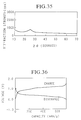
- the charge-discharge curve for the fifth cycle is shown in FIG. 36.
- the test cell On completion of the charge-discharge tests, the test cell was disassembled and the working electrode surface examined with an SEM. However there was no evidence of lithium metal deposits or dendrite growth on the working electrode surface.
- the working electrode was also analyzed with an X-ray diffraction apparatus, however no lithium metal X-ray diffraction pattern could be found.
- LiCu 0.4 Fe 0.1 N synthesized by an electrochemical reaction so as to give the amorphous form
- a test cell was then made as before with the LiCo 0.4 Fe 0.1 N in example 28 replaced by this LiCu 0.4 Fe 0.1 Fe and tests were carried out under charge-discharge conditions with a voltage range from 0.0 - 1.4V and a current of 1mA.
- the test cell On completion of the charge-discharge tests, the test cell was disassembled and the working electrode surface examined with an SEM. However there was no evidence of lithium metal deposits or dendrite growth on the working electrode surface.
- the working electrode was also analyzed with an X-ray diffraction apparatus, however no lithium metal X-ray diffraction pattern could be found.
- LiCu 0.4 Mn 0.1 N synthesized by an electrochemical reaction so as to give the amorphous form
- a test cell was then made as before with the LiCo 0.4 Fe 0.1 N in example 28 replaced by this LiCu 0.4 Mn 0.1 Mn and tests were carried out under charge-discharge conditions with a voltage range from 0.0 - 1.4V and a current of 1mA.
- the test cell On completion of the charge-discharge tests, the test cell was disassembled and the working electrode surface examined with an SEM. However there was no evidence of lithium metal deposits or dendrite growth on the working electrode surface.
- the working electrode was also analyzed with an X-ray diffraction apparatus, however no lithium metal X-ray diffraction pattern could be found.
- LiCu 0.4 Zn 0.1 N synthesized by an electrochemical reaction so as to give the amorphous form
- a test cell was then made as before with the LiCo 0.4 Fe 0.1 N in example 28 replaced by this LiCu 0.4 Zn 0.1 N, and tests were carried out under charge-discharge conditions with a voltage range from 0.0 - 1.4V and a current of 1mA.
- the test cell On completion of the charge-discharge tests, the test cell was disassembled and the working electrode surface examined with an SEM. However there was no evidence of lithium metal deposits or dendrite growth on the working electrode surface.
- the working electrode was also analyzed with an X-ray diffraction apparatus, however no lithium metal X-ray diffraction pattern could be found.
- LiCoO 2 was used for the positive electrode active material of the positive electrode 12.
- the LiCoO 2 was synthesized by the abovementioned baking method. Basically this involved weighing lithium nitrate and cobalt oxide according to the chemical formula. Then mixing, and baking in an oxygen atmosphere at 700°C. Apart from the positive electrode 12, components the same as for example 1 were used.
- Li 0.5 MnO 2 was used for the positive electrode active material of the positive electrode 12.
- the Li 0.5 MnO 2 was synthesized by the abovementioned baking method. Basically this involved weighing lithium nitrate and di manganese tri oxide according to the chemical formula. Then mixing, and baking in an oxygen atmosphere at 700°C. Apart from the positive electrode 12, components the same as for example 1 were used.
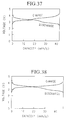
- FIG. 37 shows the charge-discharge curve for the fourth cycle.
- LiCoO 2 was used for the positive electrode active material of the positive electrode 12.
- the LiCoO 2 was synthesized by the abovementioned baking method. Basically this involved weighing lithium nitrate and cobalt oxide according to the chemical formula. Then mixing, and baking in an oxygen atmosphere at 700°C. Apart from the positive electrode 12, components the same as for example 12 were used.
- Li 1.5 Co 0.4 N made by the abovementioned sputtering method was used for the negative electrode active material container of the negative electrode 2.
- a standard high frequency sputtering apparatus was used with a sintered body of chemical formula Li 2.5 Co 0.4 N as a target, and a 16mm diameter stainless steel plate as a base plate. After evacuating the chamber, Ar gas was introduced, and the high frequency sputtering apparatus operated with a power of 200 watts and with the Ar gas atmosphere at a pressure of lPa, so that a thin film of amorphous Li 1.5 Cu 0.4 N was formed on the stainless base plate, giving the negative electrode 2. The resultant thin film thickness was 5 microns.
- This negative electrode 2 was then spot welded to the negative electrode case 9.
- Li 0.5 MnO 2 made by the abovementioned sputtering method was used for the positive electrode active material of the positive electrode 12.
- a standard high frequency sputtering apparatus was used with a sintered body of chemical composition Li 0.5 MnO 2 as a target, and a 16mm diameter stainless steel plate as a base plate. After evacuating the chamber, a mixture of Ar and O 2 gas was introduced, and the high frequency sputtering apparatus operated with a power of 200 watts and with the atmosphere of the Ar and O 2 gas at a pressure of 1Pa, so that a thin film of amorphous Li 0.5 MnO 2 was formed on the stainless steel base plate.
- This thin film was then annealed at 700°C in an atmosphere of oxygen, thus giving the positive electrode 12.
- the resultant thin film thickness was 35 microns.
- This positive electrode 12 was then spot welded to the positive electrode case 11. Apart from the negative electrode 2 and the positive electrode 12, components the same as for example 1 were used.
- the overall size of the battery can be made thin, thus lending the battery to special applications such as forming on top of an electronic substrate, to meet special thin size requirements.
- Li 0.5 Ni 0.5 V 0.5 O 2 was used for the positive electrode active material of the positive electrode 12.
- the Li 0.5 Ni 0.5 V 0.5 O 2 was synthesized by the abovementioned baking method. Basically this involved weighing lithium nitrate and nickel oxide and vanadium penta oxide according to the chemical formula. Then mixing, and baking in an oxygen atmosphere at 700°C. Apart from the positive electrode 12, components the same as for example 12 were used.
Landscapes
- Chemical & Material Sciences (AREA)
- Engineering & Computer Science (AREA)
- Chemical Kinetics & Catalysis (AREA)
- Electrochemistry (AREA)
- General Chemical & Material Sciences (AREA)
- Materials Engineering (AREA)
- Manufacturing & Machinery (AREA)
- Inorganic Chemistry (AREA)
- Battery Electrode And Active Subsutance (AREA)
- Inorganic Compounds Of Heavy Metals (AREA)
Abstract
Description
- The present invention relates to lithium secondary batteries, negative electrode material for use in those batteries, and the methods of manufacture.
- Recently there has been progress with the miniaturization, weight reduction, and portability of electronic appliances, resulting in the requirement for development of secondary cells having a high energy density as the power source. As a secondary cell to meet this requirement a lithium secondary battery using a lithium metal as a negative electrode active material has been contemplated.
- A lithium secondary battery basically has a higher voltage and a higher energy density than other types of conventional secondary batteries, for example nickel cadmium batteries or lead storage batteries.
- However, in general with lithium secondary batteries using lithium metal as the negative electrode active material, needle-shaped lithium (dendrite) is produced during charging. Furthermore, during discharging the needle-shaped lithium collapses and dissociates from the electrode base. Hence lithium which does not contribute to the charging-discharging is produced. Moreover, since the dissociated metallic lithium particles are extremely active, the lithium metal is consumed by reaction with the electrolyte.
- For these reasons, cells wherein lithium metal is used for the negative electrode active material have the inherent problem of a short cycle life. Hence in cell systems using lithium metal or lithium alloy for the negative electrode, there is the situation wherein it is difficult to maintain the cycle life.
- Moreover, when lithium metal is used for the negative electrode, then theoretically the capacity per volume of negative electrode is around 2062 mAh/cm3. However since the cell is generally provided with an amount of lithium to give approximately three times the cell capacity to compensate for the abovementioned deterioration in the metallic lithium, the capacity per volume of negative electrode becomes 687 mAh/cm3.
- Therefore, as a new negative electrode active material container, as a substitute for the lithium metal or lithium alloy, a material which utilizes a lithium intercalation reaction has gained attention. For this substitute material, a carbonaceous material such as natural graphite or synthetic graphite, or an inorganic material such as di-niobium-penta-oxide (Nb2O5), molybdenum dioxide (MoO2), or titanium disulfide (TiS2) have been investigated.
- With these materials, since the lithium is retained in an ionized state within the skeletal structure, there is more stability than with the lithium negative electrode in a chemically active metal state. Moreover since there is no growth of dendrite as when lithium metal is used for the negative electrode active material, then the cycle life is improved.
- Furthermore, with the construction wherein a carbonaceous material is used for the negative electrode active material container, a practical cell having a charge-discharge capacity of 150 - 370 mAh/g has been realized, wherein the lithium ions can be stably inserted and extracted in a low electrode potential range of 0 - 1V relative to a lithium reference electrode (metallic lithium).
- Incidentally, when a carbonaceous material is used for the negative electrode active material container, then if most of the lithium content is LiC6, the capacity per mass is relatively large at 370 mAh/g. However, the specific gravity of the carbonaceous material is low at 1.6 - 2.2 g/cm3, and if the electrode is made in sheet form, then this specific gravity reduces further to 1 - 1.5 g/cm3. Therefore, the capacity per negative electrode volume reduces to 370 - 555 mAh/cm3. This however is the theoretical value, and in practice is reduced even further to 200 - 370 mAh/cm3.
- Thus when a carbonaceous material is used for the negative electrode, the capacity ratio per negative electrode volume becomes approximately half of that for the abovementioned case with lithium metal. There is thus the problem that the energy density of a cell using a carbonaceous material for the negative electrode is quite small compared to that for a cell using lithium metal for the negative electrode.
- Moreover, with the abovementioned inorganic materials such as di-niobium-penta-oxide, then in general the electrode potential at which the lithium ions can be stably inserted and extracted is high at 0.5 - 2.0V relative to a lithium reference electrode. There is thus the problem when these inorganic materials are used for the negative electrode, in that the operating potential of the lithium secondary battery is reduced to 0.5 - 2.0V, and hence a high voltage cannot be attained.
- Also, since the charge-discharge capacity is small at 100 - 200 mAh/g, there is the problem that the energy density of a cell using an inorganic material for the negative electrode is quite small compared to a cell using lithium material for the negative electrode.
- Furthermore, in order to achieve a high cell voltage and high energy density, then at low potentials of 0.0 - 1.5V relative to a lithium reference electrode, the electrochemical reaction for insertion and extraction of the lithium ions must be reversible. However, when the inorganic material operates at low potentials of 0.0 - 1.5V, the electrochemical reaction in the insertion and extraction of the lithium ions becomes non reversible, and the inorganic material is said to decompose. There is however practically no information of how the inorganic material operates at low potentials of 0.0 - 1.5V relative to a lithium reference electrode.
- It has been reported however (Abstracts of the Sixty First Meeting of the Electrochemical Society (Japan) p.31, 1994), that of the inorganic materials, a crystalline material having a composition of Li2.5Co0.5N, has a capacity ratio of 330 mAh/g at a potential close to 1V relative to a lithium reference electrode.
- However, with this crystalline Li2.5Co0.5N, lithium is only used in charging and discharging in a range from 0 - 0.755 Li/mol. Hence the capacity ratio is small at 330 mAh/g, and thus does not approach the theoretical capacity for carbonaceous materials. Moreover, since the specific gravity of the Li2.5Co0.5N at around 2.3g/cm3 is somewhat higher than that of the carbonaceous materials, then the capacity per negative electrode volume remains at approximately the same as that for the carbonaceous material. Hence there is the problem that the energy density of a cell using Li2.5Co0.5N for the negative electrode is also quite small compared to that for a cell wherein lithium metal is used for the negative electrode.
- Furthermore, with the crystalline Li2.5Co0.5N, since the lithium is filled in the structure, then when this is used for the negative electrode of a lithium secondary battery, it is necessary to operate the cell so as to extract lithium ions from the negative electrode. That is, the cell must be operated from after discharging.
- Incidentally, when a transition metal oxide containing lithium and having a high electrode potential relative to lithium metal of greater than 3V is used for the positive electrode of a lithium secondary battery, it is necessary to operate the cell so as to extract lithium ions from the positive electrode. That is, the cell must be operated from after charging.
- Consequently, it is not possible to assemble together a negative electrode made from crystalline Li2.5Co0.5N, with a positive electrode made from a transition metal oxide containing lithium and having such a high voltage. Therefore, when a negative electrode made from crystalline Li2.5Co0.5N is used, there is the problem in that it is not possible to obtain both the high voltage and the high energy density.
- The negative electrode material for use in lithium secondary batteries, of the present invention, contains a negative electrode active material container made from an amorphous transition metal nitride containing lithium represented by the chemical formula Li1+xMyN. Here M represents one or more elements selected from; a transition metal, group IIIA, group IVA, and group VA, and contains at least a transition metal, x is within the range from -0.2 - 2.0, and y is within the range from 0.1 - 0.6.
- Moreover, the lithium secondary battery of the present invention is one which uses this novel negative electrode material.
- With the lithium secondary battery of the present invention, the problems with the abovementioned conventional technology are overcome, giving a battery of high energy density with large charge-discharge capacity, and a long cycle life.
-
- FIG. 1 is a cross-sectional view of an example of a lithium secondary battery;
- FIG. 2 is a graph showing an X-ray diffraction pattern of LiCo0.4N of example 2;
- FIG. 3 is a cross-sectional view of a test cell used with the examples;
- FIG. 4 is a graph showing a charge-discharge curve for a third cycle of a test cell wherein LiCo0.4N of example 3 is used for the negative electrode;
- FIG. 5 is a graph showing a charge-discharge curve for a third cycle of a test cell wherein LiCo0.4N of example 4 is used for the negative electrode;
- FIG. 6 is a graph showing an X-ray diffraction pattern of LiCo0.3N of example 5;
- FIG. 7 is a graph showing an X-ray diffraction pattern of Li1.2Co0.4N of example 6;
- FIG. 8 is a graph showing an X-ray diffraction pattern of LiNi0.4N of example 7;
- FIG. 9 is a graph showing a charge-discharge curve for a third cycle of a test cell wherein LiNi0.4N of example 7 is used for the negative electrode;
- FIG. 10 is a graph showing an X-ray diffraction pattern of LiCu0.4N of example 8;
- FIG. 11 is a graph showing a charge-discharge curve for a third cycle of a test cell wherein LiCu0.4N of example 8 is used for the negative electrode;
- FIG. 12 is a graph showing an X-ray diffraction pattern of Li1.5Cu0.4N of example 9;
- FIG. 13 is a graph showing a charge-discharge curve for a fifth cycle of a lithium secondary battery according to example 10;
- FIG. 14 is a graph showing a charge-discharge curve for a fifth cycle of a lithium secondary battery according to example 11;
- FIG. 15 is a graph showing a charge-discharge curve for a fifth cycle of a lithium secondary battery according to example 12;
- FIG. 16 is a graph showing a charge-discharge curve for a fifth cycle of a lithium secondary battery according to example 14;
- FIG. 17 is a graph showing a charge-discharge curve for a fifth cycle of a lithium secondary battery according to example 15;
- FIG. 18 is a graph showing a charge-discharge curve for a fifth cycle of a lithium secondary battery according to example 19;
- FIG. 19 is a graph showing a charge-discharge curve for a fifth cycle of a lithium secondary battery according to control example 1;
- FIG. 20 is a graph showing a charge-discharge curve for a second cycle of a test cell wherein LiCo0.5N of example 20 is used for the working electrode;
- FIG. 21 is a graph showing a charge-discharge curve for a second cycle of a test cell wherein Li1.15Co0.5N of example 21 is used for the working electrode;
- FIG. 22 is a graph showing a charge-discharge curve for a second cycle of a test cell wherein Li1.24Co0.5N of example 22 is used for the working electrode;
- FIG. 23 is a graph showing a charge-discharge curve for a second cycle of a test cell wherein Li1.05Co0.4N of example 23 is used for the working electrode;
- FIG. 24 is a graph showing a charge-discharge curve for a second cycle of a test cell wherein Li0.96Co0.4N of example 24 is used for the working electrode;
- FIG. 25 is a graph showing a charge-discharge curve for a second cycle of a test cell wherein Li0.95Co0.6N of example 25 is used for the working electrode;
- FIG. 26 is a graph showing a charge-discharge curve for a second cycle of a test cell wherein Li1.5Ni0.5N of example 26 is used for the working electrode;
- FIG. 27 is a graph showing a charge-discharge curve for a second cycle of a test cell wherein Li1.09Cu0.4N of example 27 is used for the working electrode;
- FIG. 28 is a graph showing an X-ray diffraction pattern of LiCo0.4Fe0.1N of example 28;
- FIG. 29 is a graph showing a charge-discharge curve for a fifth cycle of a test cell wherein LiCo0.4Fe0.1N of example 28 is used for the working electrode;
- FIG. 30 is a graph showing an X-ray diffraction pattern of LiCo0.4Ni0.1N of example 29;
- FIG. 31 is a graph showing a charge-discharge curve for a fifth cycle of a test cell wherein LiCo0.4Ni0.1N of example 29 is used for the working electrode;
- FIG. 32 is a graph showing an X-ray diffraction pattern of LiCo0.4Cu0.1N of example 32;
- FIG. 33 is a graph showing a charge-discharge curve for a fifth cycle of a test cell wherein LiCo0.4Cu0.1N of example 32 is used for the working electrode;
- FIG. 34 is a graph showing a charge-discharge curve for a fifth cycle of a test cell wherein LiCo0.1Cu0.4N of example 33 is used for the working electrode;
- FIG. 35 is a graph showing an X-ray diffraction pattern of LiNi0.1Cu0.4N of example 39;
- FIG. 36 is a graph showing a charge-discharge curve for a fifth cycle of a test cell wherein LiNi0.1Cu0.4N of example 39 is used for the working electrode;
- FIG. 37 is a graph showing a charge-discharge curve for a fourth cycle of a lithium secondary battery according to example 44; and
- FIG. 38 is a graph showing a charge-discharge curve for a fourth cycle of a lithium secondary battery according to example 46;
- With the negative electrode material of the present invention, an amorphous transition metal nitride containing lithium represented by the chemical formula Li1+xMyN (where M represents one or more elements selected from; a transition metal, group IIIA, group IVA, and group VA, and contains at least a transition metal, x is within the range from -0.2 - 2.0 and y is within the range from 0.1 - 0.6) is used for the negative electrode active material container. It is both novel and excellent.
- Alternatively a negative electrode material having a negative electrode active material container made from an amorphous transition metal nitride containing lithium represented by the chemical formula Li3-p-qMpN is both novel and excellent. Here M is one or more elements selected from; a transition metal, group IIIA, group IVA, and group VA, and contains at least a transition metal, p is within the range from 0.1 - 1.0, and q is within the range from 0.8 - 1.8.
- With the negative electrode active material container of the present invention, the lithium ions can be stably inserted and extracted in the region of low electrode potential below 1.5V relative to a lithium reference electrode (metallic lithium), and thus has a high capacity charge-discharge range.
- With the present invention, the transition metal represented by M or M' means an element in the periodic table; from Sc of atomic number 21 to Zn of
atomic number 30, from Y of atomic number 39 to Cd of atomic number 48, or from La of atomic number 57 to Hg of atomic number 80. Moreover the group IIIA elements means the elements B, Al, Ga, In, Tl, the group IVA elements means the elements C, Si, Ge, Sn, Pb, and the group VA elements means the elements P, As, Sb, Bi. Consequently, LiMN (where M represents one or more elements selected from; a transition metal, group IIIA, group IVA, and group VA, and contains at least a transition metal) can be for example; LiCoN, LiNiN, LiCuN, LiCoFeN, LiCoNiN, LiCoCuN, LiNiCuN, LiCoAlN, LiCoGeN, or LiCoAsN. - With the Li1+xMyN, if x is less than -0.2, then the Li1+xMyN dissociates so that there is the possibility of being unable to effect charging-discharging. Moreover, if x is greater than 2.0, then the capacity of a cell using this as the negative electrode material drops. It is thus preferable for x to be within the range of -0.2 - 0.5, and ideally to be zero.
- Moreover, if y is less than 0.1 the insulation properties increase, thus degrading the cell performance of a cell using this for the negative electrode material, and giving rise to the possibility of dissociation of the Li1+xMyN. On the other hand, if y is greater than 0.6, the solid-solubility of the transition metal element becomes difficult. It is thus more preferable for y to be less than 0.5.
- The compound represented by the chemical formula Li1+xMyN (-0.2 ≦ x ≦ 2.0, 0.1 ≦ y ≦ 0.6) or Li3-p-qMpN (0.1 ≦ p ≦ 1.0, 0.8 ≦ q ≦ 1.8), for example; Li1+xCoyN, Li1+xNiyN, or Li1+xCuyN; or Li1+xCoy'Niy''N, Li1+xCoy'Cuy''N, or Li1+xNiy'Cuy'' N (where 0.1 ≦ y'+y'' (=y) ≦ 0.6), being the negative electrode active material container of the present invention, is heretofore unknown, and exists in a new phase (referred to hereunder as a 7 phase). This 7 phase is one in which the lithium ions exist in a dissociated condition. In X-ray powder diffraction measurements with θ as an angle of diffraction, it has no diffraction peak within a range from 30° to 70° with 2 θ, and is thus amorphous.
- This γ phase allows the reversible extraction and insertion of the lithium ions, as well as having a high charge-discharge capacity.
- As described later, the amorphous Li1+xMyN of the present invention is obtained by extracting the lithium ions from a transition metal nitride containing lithium, or by forming a thin film. Such a once amorphized Li1+xMyN cannot be subsequently crystallized, even if a quantity containing lithium ions is added, and thus continues to retain the amorphous condition. Consequently, the Li1+xMyN of the present invention made by passing once thorough an amorphizing process has a completely different structure from a transition metal nitride containing crystalline lithium, even if it can be represented by the same chemical formula, for example crystalline Li2.5-xCo0.5N (0 ≦ x ≦ 0.755), and has completely different characteristics on a macro scale.
- With the present invention, the charge-discharge capacity is remarkably increased by using the 7 phase having a high charge-discharge capacity, for charging-discharging. That is to say, in X-ray powder diffraction measurements with an angle of diffraction of 2 θ, it has no diffraction peak from 30° to 70°, and is thus amorphous. Hence cell performance is improved.
- With the negative electrode active material container in the present invention, the charge-discharge capacity is large, and the specific gravity is the same as or higher than that of carbonaceous materials. Hence the charge-discharge capacity per negative electrode unit volume is also greater than that for the carbonaceous materials heretofore used for the negative electrode active material container.
- Moreover, with the negative electrode active material container in the present invention, since lithium diffusion is fast and polarization due to charging-discharging is minimal, then charging-discharging at high currents is possible.
- Also, high voltage, high energy density can be achieved without a marked drop in cell operating voltage.
- Furthermore, since a sudden drop in capacity due to repeated charging-discharging is not observed, then an very long cycle life can be obtained. Moreover, since deposits of lithium metal or dendrite growth is not observed on the electrode surface of the negative electrode active material container with repeated charging-discharging, then the cycle life can be lengthened.
- Consequently, by using the amorphous transition metal nitride containing lithium of the present invention as the negative electrode active material container, then a lithium secondary battery with high energy density, a large charge - discharge capacity, and a long cycle life can be realized.
- Moreover, a transition metal nitride containing lithium represented by the chemical formula Li1+xMyN (where M is one or more elements selected from; a transition metal, group IIIA, group IVA, and group VA, and contains at least a transition metal, x is within the range from -0.2 - 2.0, and y is within the range from 0.1 - 0.6) and furthermore, when x+y < 2 is satisfied, is a shortage of lithium within the structure. Consequently, when this is used for the negative electrode of the lithium secondary battery, the lithium ions move in the direction for insertion into the negative electrode. That is, the cell can be operated from after charging. Therefore, this can be combined with a positive electrode active material made from a transition metal oxide containing lithium and having a high voltage with an electrode potential relative to a lithium metal electrode above 3 volts. That is to say, this can be combined with a transition metal nitride containing lithium represented by the chemical formula Li2M'O2 (where M' indicates an element of one type or two types belonging to the transition metals, and z is the range from 0.5 - 1.0) as the positive electrode active material. Consequently with the lithium secondary battery, a higher operating voltage, a large charge-discharge capacity, a high energy density, and a long cycle life can be obtained.
- The amorphous transition metal nitride containing lithium for the negative electrode active material container of the present invention is obtained for example by amorphizing a transition metal nitride containing lithium (referred to hereunder as a precursor), represented by the chemical formula Li3-yMyN (where M represents one or more elements selected from; a transition metal, group IIIA, group IVA, and group VA, and contains at least a transition metal, and y is within the range from 0.1 - 0.6).
- The amorphizing method may involve for example; a method wherein the lithium ions are dissociated from the precursor by a chemical reaction; a method wherein the lithium ions are dissociated from the precursor by an electrochemical reaction; or a method wherein an amorphous thin film is formed from the precursor by a sputtering method.
- Examples of the synthesizing methods will now be explained. At first, the precursor can be synthesized using lithium (Li) or lithium nitride (Li3N) and a transition metal or a transition metal nitride as the initial raw materials, weighed and mixed in predetermined quantities so as to give a compounding ratio for a chemical formula Li3-yMyN (where M indicates an element belonging to a transition metal, and y is a range from 0.1 - 0.6), and then baked in an atmosphere of nitrogen. The lithium ions are then dissociated from the precursor by a chemical reaction, or an electrochemical reaction, thus giving the amorphous form.
- For amorphizing by means of a chemical reaction, there is a method wherein a predetermined quantity of iodine (I2) is dissolved in dehydrated acetonitrile, and the precursor then added thereto, mixed and filtered.
- For amorphizing by means of an electrochemical reaction, there is a method by charge taking part in an oxidation-reduction system so as to dissociate lithium ions from a working electrode, wherein the precursor as a working electrode, the lithium metal as a counter electrode and a nonaqueous electrolyte containing a lithium salt as the electrolyte are used with a predetermined quantity of electricity.
- Moreover, for amorphizing using the sputtering method, there is a method wherein a sintered body of the precursor is used as a target in a normal sputtering apparatus, and an amorphous thin film is formed thereon in an atmosphere of Ar gas.
- With this method, the negative electrode in the present invention, can be made as a thin film. Hence the cell can be made extremely thin by having the negative electrode in the form of a thin film. With a cell thus reduced in thickness, a lithium secondary battery can be formed for example on top of an integrated circuit, so that weight reduction, miniaturization and slimming of various electronic devices can be advanced to unprecedented levels.
- When as described above a negative electrode material containing a negative electrode active material container is used in the lithium secondary battery, then for the active material container contained in the positive electrode material it is possible to use for example an oxide compound or a sulphide compound of a transition metal such as, titanium, molybdenum, tungsten, niobium, vanadium, manganese, iron, chrome, nickel, cobalt or the like containing lithium.
- Furthermore, with the lithium secondary battery in which the negative electrode active material container is combined with a transition metal oxide containing lithium represented by the chemical formula LizM'O2 (where M' represents one element or two or more elements belonging to the transition metals, and z is the range from 0.5 - 1.0) as the positive electrode active material, then the lithium ions can be stably inserted and extracted within the voltage range of 2.5 - 4.2V, and can thus have a high capacity charge-discharge region. Now if z is less than 0.5, it becomes difficult to form the oxide compound, and similarly this is so if z is greater than 1.0.
- Of the compounds LizM'O2, those such as LiNiO2, LiCoO2, LiNi0.5Co0.5O2, Li0.5MnO2, Li0.5Ni0.5V0.5O2, Li0.5Co0.5V0.5O4, LiFeO2, and LiMnO2 for which a high voltage with an electrode potential relative to a lithium metal electrode of more than 3V, and a high energy density can be expected, are well suited for the positive electrode active material.
- Such a construction for a lithium secondary battery using a transition metal nitride containing lithium and represented by the chemical formula Li1+xMyN as the negative electrode active material container, and using a transition metal oxide containing lithium and represented by the chemical formula Li2M'O2 (where M' indicates an element of one type or two types belonging to the transition metals, and z is the range from 0.5 - 1.0) as the positive electrode active material, results in a lithium secondary battery with a high voltage, a high energy density, and a large charge-discharge capacity, as well as a long cycle life.
- The transition metal oxide containing lithium represented by the chemical formula LizM'O2 (where M' indicates an element of one type or two types belonging to the transition metals, and z is the range from 0.5 - 1.0) being the positive electrode active material of the present invention, can be synthesized by a normal baking process, or a sputtering method in thin film formation technology.
- For example, in synthesizing LiNiO2 by the baking method, this can be synthesized by weighing lithium nitrate and nickel oxide according to the chemical formula, then mixing, and baking at 700°C in an atmosphere of oxygen.
- Moreover, in synthesizing Li0.5MnO2 for example by the sputtering method, this can be synthesized using a sintered material with a composition of Li0.5MnO2 as a target and forming a thin film thereon in an atmosphere of a mixture of Ar and O2 gas, and then annealing the thin film in an atmosphere of oxygen at 700°C.
- Furthermore, for the positive electrode active material, a sulphide compound represented by the chemical formula Liwfe2(SO4)3 (0 < w ≦ 2.0) is also excellent. With this substance, as well as being low cost and using materials which are abundantly available, the discharge energy is high and a cell of long cycle life is possible
- For the electrolyte used in the present invention, a nonaqueous electrolyte, an electrolyte impregnated polymer matrix, a polymer electrolyte, a solid state electrolyte, or a molten salt electrolyte, are appropriate.
- The nonaqueous electrolyte is in general made from a solvent with a lithium salt dissolved therein. As a solvent for the nonaqueous electrolyte, at least one or more solvents selected from: an ester of chain structure such as ethylene carbonate (EC), propylene carbonate (PC), dimethyl carbonate (DMC), diethyl carbonate (DEC), methyl ethyl carbonate (MEC); a γ-lactone such as γ-butyrolactone; an ether of chain structure such as 1,2-dimethoxyethane (DME), 1,2-diethoxyethane (DEE), 1-ethoxy,2-methoxy ethane (EME); an ether of ring structure such as tetrahydrofuran; and a nitrile such as acetonitrile, can be used. In particular, a cell using ethylene carbonate exhibits good cell characteristics.
- By using a mixture solvent of ethylene carbonate and an ester of chain structure, for example dimethyl carbonate, diethyl carbonate, or methyl ethyl carbonate, or by using a mixture solvent of ethyl carbonate and an ether of chain structure, for example 1,2-dimethoxyethane, 1,2-diethoxyethane, 1-ethoxy,2-methoxy ethane, particularly good cell characteristics are displayed.
- For the solute of nonaqueous electrolyte, a lithium salt such as LiAsF6, LiBF4, LiPF6, LiAlCl4, LiClO4, LiCF3SO3, LiSbF6, LiSCN, LiCl, LiC6H5SO3, LiN(CF3SO2), LiC(CF3SO2)3, or C4F9SO3Li, or a mixture of these may be used.
- For the polymer electrolyte, a system with a lithium salt such as LiCF3SO3 dissolved in a polyetherized compound such as poly (ethylene oxide) or a system with above-mentioned nonaqueous electrolyte impregnated into a polymer latex, may be used.
- For the solid state electrolyte, a system such as an Li2S-SiS2-Li3PO4 system or an Li4SiO4-Li3VO4 system may be used.
- For the molten salt electrolyte, for example an AlCl3-1-butyl-pyridinium chloride - LiCl system, or an AlCl3-1-ethyl-3-methyl-imidazolium chloride - LiCl system, may be used.
- As follows is a description of examples of the present invention. These examples do not limit the present invention, which can be freely modified within the scope of the claims.
- FIG. 1 shows an example of a lithium secondary battery applicable to the present invention. With this example, a
gasket 8 is provided inside apositive case 11, and anegative case 9 is fitted into thegasket 8. Anegative electrode 2 is provided inside thenegative case 9, and apositive electrode 12 is positioned opposite to thenegative electrode 2. Anelectrolyte 3 is filled between thenegative electrode 2 and thepositive electrode 12, with aseparator 4 disposed therein. - For the negative electrode active material container of the
negative electrode 2, a substance containing for example LiCo0.4N is applicable. When LiCo0.4N is used, then the active material container is made by mixing; the amorphous LiCo0.4N synthesized by the chemical reaction as mentioned above, acetylene black as a conductive agent, and polytetrafluoroethylene as a binder, in a ratio by weight of 90:7:3, and then rolling into a sheet, and punching to a diameter of 16mm. Moreover, thenegative electrode 2 is secured to thenegative case 9 by covering with acollector body 13 made from Ni mesh which is spot welded to thenegative case 9. - For the
electrolyte 3, a nonaqueous electrolyte is used. This has 1 mole/liter of LiClO4 dissolved in a mixture solvent of EC and DEE (in a volumetric ratio of 1:1). - The
separator 4 is made from a perforated film of polypropylene or polyethylene. - For example a lithium nickel compound oxide such as LiNiO2 is used for the positive electrode active material of the
positive electrode 12. This positive electrode is made by synthesizing LiNiO2 (positive electrode active material) by a normal baking method, and then mixing this LiNiO2, acetylene black as a conductive agent, and polytetrafluoroethylene as a binder, in a ratio by weight of 90:7:3, and then rolling into a sheet, and punching to a diameter of 16mm. Thepositive electrode 12 is secured to thepositive case 11 by covering with a collector body 7 made from Ti mesh which is spot welded to the inside of thepositive case 11. - The capacity of the negative electrode and the positive electrode are adjusted so as to be the same. Moreover, the volumes of the negative electrode and the positive electrode are made so that their sum is equal to the interior volume of the lithium secondary battery
- The
gasket 8 is for maintaining electrical insulation between thenegative case 9 and thepositive case 12. The opening rim of thepositive case 11 is bent inwards and crimped over to thereby close off and seal the contents inside the cell. - FIG. 2 shows a diffraction pattern measured using an X-ray powder diffraction apparatus, of LiCo0.4N synthesized by a chemical reaction so as to give the amorphous form. Copper was used in the tube of the X-ray diffraction apparatus, and measurements were made at a tube voltage of 30kV and a tube current of 100mA.
- As is apparent from FIG. 2, with this LiCo0.4N, a broad peak is observed in the vicinity of 2 θ = 25°. However in the range for 2 θ from 10 - 70 degrees, except for this peak there is no evidence of a diffraction peak, thus verifying this LiCo0.4N to be amorphous.
- FIG. 3 shows a test cell used in performance assessment of the negative electrode active material container of the lithium secondary battery according to the present invention. This test cell is an experimental type used for experiments on the negative electrode active material container, and as such is not a practical lithium secondary battery.
- With this test cell, negative electrode active material containers serving as experimental samples, were used as a working
electrode 14. The respective materials (experimental samples) were formed into the workingelectrode 14 by mixing with acetylene black as a conductive agent, and polytetrafluoroethylene as a binder, in a ratio by weight of 70 : 25 : 5, and then rolling into a sheet, and punching to a diameter of 16mm. The workingelectrode 14 was secured to a workingelectrode case 16 by covering with a net-liketitanium collector body 15. The workingelectrode case 16 was made by press forming a stainless steel plate. Agasket 8 was provided inside the workingelectrode case 16, and acounter electrode case 17 fitted into thegasket 8. Thecounter electrode case 17 was also made by press forming a stainless steel plate. Thegasket 8 maintained electrical insulation between thecounter electrode case 17 and the workingelectrode case 16. Acounter electrode 18 made from metallic lithium was provided inside thecounter electrode case 17. With thecounter electrode 18, a lithium metal foil of a predetermined thickness, punched to a diameter of 16mm, was bonded to thecounter electrode case 17. Aseparator 4 made from a perforated film of polypropylene or polyethylene was located between the workingelectrode 14 and thecounter electrode 18. Moreover, anonaqueous electrolyte 19 was filled between the workingelectrode 14 and thecounter electrode 18. Thenonaqueous electrolyte 19 had LiClO4 dissolved as one mole/liter in a mixture solvent of a 1: 1 volume ratio of EC and DEE. - With a test cell with the abovementioned amorphous LiCo0.4N synthesized by a chemical reaction used for the working
electrode 14, charge-discharge tests were carried out with a voltage range from 0.0 - 1.4V and a current of 1mA. The charge-discharge curve for the third cycle is shown in FIG. 4. - As is clear from FIG. 4, with this LiCo0.4N, reversible insertion and extraction of the lithium ions was possible within the voltage range from 0.0 - 1.4V. Steady charging and discharging was repeated for more than 50 cycles without observing any accompanying sudden drop in capacity. A capacity of 56 mAh was obtained under this steady repetition of the charging and discharging, and converting this to capacity per weight of negative electrode active material container of the working electrode, gives a capacity ratio of 800mAh/g.
- On completion of the charge-discharge tests, the test cell was disassembled and the working electrode surface examined with a scanning electron microscope (SEM). However there was no evidence of lithium metal deposits or dendrite growth on the surface of the working electrode. The working electrode was also analyzed with an X-ray diffraction apparatus, however no lithium metal X-ray diffraction pattern was found.
- The test cell of example 3 was tested under charge-discharge conditions with a voltage range from 0.0 - 1.0V and a current of 1mA. The charge-discharge curve for the third cycle is shown in FIG. 5.
- As is clear from FIG. 5, with this LiCo0.4N, reversible insertion and extraction of the lithium ions was possible within the voltage range from 0.0 - 1.0V. Steady charging and discharging was repeated for more than 50 cycles without observing any accompanying sudden drop in capacity. A capacity of 48mAh was obtained under this steady repetition of the charging and discharging, and converting this to capacity per weight of negative electrode active material container of the working electrode, gives a capacity ratio of 600mAh/g.
- On completion of the charge-discharge tests, the test cell was disassembled and the working electrode surface examined with an SEM. However there was no evidence of lithium metal deposits or dendrite growth on the surface of the working electrode. The working electrode was also analyzed with an X-ray diffraction apparatus, however no lithium metal X-ray diffraction pattern was found.
- With LiCo0.3N synthesized by an electrochemical reaction so as to give the amorphous form, a diffraction pattern was measured using an X-ray powder diffraction apparatus. Copper was used in the tube of the X-ray diffraction apparatus, and measurements were made at a tube voltage of 30kV and a tube current of 100mA.
- As shown in FIG. 6, with this LiCo0.3N, a broad peak is observed in the vicinity of 2 θ = 25°. However in the range for 2 θ from 10 - 70 degrees, except for this peak there is no evidence of a diffraction peak, thus verifying this LiCo0.3N to be amorphous.
- Tests were also made with this LiCo0.3N substituted for the LiCo0.4N of the working
electrode 14 of example 3. The working electrode was made by mixing; the abovementioned amorphous LiCo0.3N synthesized by the electrochemical reaction, acetylene black as a conductive agent, and polytetrafluoroethylene as a binder, in a ratio by weight of 70:25:5, and then rolling into a sheet, and punching to a diameter of 16mm. Apart from the workingelectrode 14, components the same as for example 3 were used. - Tests were made using this test cell under charge-discharge conditions with a voltage range from 0.0 - 1.2V and a current of 1mA. With this LiCo0.3N also, reversible insertion and extraction of the lithium ions was possible. Steady charging and discharging was repeated for more than 50 cycles without observing any accompanying sudden drop in capacity. A capacity of 58 mAh was obtained under this steady repetition of the charging and discharging, and converting this to capacity per weight of negative electrode active material container of the working electrode, gives a capacity ratio of 850mAh/g.
- On completion of the charge-discharge tests, the test cell was disassembled and the working electrode surface examined with an SEM. However there was no evidence of lithium metal deposits or dendrite growth on the working electrode surface. The working electrode was also analyzed with an X-ray diffraction apparatus, however no lithium metal X-ray diffraction pattern could be found.
- With Li1.2Co0.4N synthesized by an electrochemical reaction so as to give the amorphous form, a diffraction pattern was measured using an X-ray powder diffraction apparatus. Copper was used in the tube of the X-ray diffraction apparatus, and measurements were made at a tube voltage of 30kV and a tube current of 100mA.
- As shown in FIG. 7, with the Li1.2Co0.4N, a broad peak is observed in the vicinity of 2 θ = 25°. However in the range for 2 θ from 10 - 70 degrees, except for this peak there is no evidence of a diffraction peak, thus verifying this Li1.2Co0.4N to be amorphous.
- Tests were also made with the Li1.2Co0.4N substituted for the LiCo0.4N of the working
electrode 14 of example 3. This working electrode was made by mixing; the abovementioned amorphous Li1.2Co0.4N synthesized by the electrochemical reaction, acetylene black as a conductive agent, and polytetrafluoroethylene as a binder, in a ratio by weight of 70:25:5, and then rolling into a sheet, and punching to a diameter of 16mm. Apart from the workingelectrode 14, components the same as for example 3 were used.
Tests were made using this test cell under charge-discharge conditions with a voltage range from 0.0 - 1.4V and a current of 1mA. With this Li1.2Co0.4N also, reversible insertion and extraction of the lithium ions was possible. Steady charging and discharging was repeated for more than 50 cycles without observing any accompanying sudden drop in capacity. A capacity of 55 mAh was obtained under this steady repetition of the charging and discharging, and converting this to capacity per weight of negative electrode active material container of the working electrode, gives a capacity ratio of 780mAh/g. - On completion of the charge-discharge tests, the test cell was disassembled and the working electrode surface examined with an SEM. However there was no evidence of lithium metal deposits or dendrite growth on the working electrode surface. The working electrode was also analyzed with an X-ray diffraction apparatus, however no lithium metal X-ray diffraction pattern could be found.
- With LiNi0.4N synthesized by a chemical reaction so as to give the amorphous form, a diffraction pattern was measured using an X-ray powder diffraction apparatus. Copper was used in the tube of the X-ray diffraction apparatus, and measurements were made at a tube voltage of 30kV and a tube current of 100mA.
- As shown in FIG. 8, with this LiNi0.4N, a broad peak is observed in the vicinity of 2 θ = 25°. However in the range for 2 θ from 10 - 70 degrees, except for this peak there is no evidence of a diffraction peak, thus verifying this LiNi0.4N to be amorphous.
- Tests were also made with this LiNi0.4N substituted for the LiCo0.4N of the working
electrode 14 of example 3. The working electrode was made by mixing; the abovementioned amorphous LiNi0.4N synthesized by the chemical reaction, acetylene black as a conductive agent, and polytetrafluoroethylene as a binder, in a ratio by weight of 70:25:5, and then rolling into a sheet, and punching to a diameter of 16mm. Apart from the workingelectrode 14, components the same as for example 3 were used. - Tests were made using this test cell under charge-discharge conditions with a voltage range from 0.0 - 1.2V and a current of 1mA. The charge-discharge curve for the third cycle is shown in FIG. 9.
- As is clear from FIG. 9, with this LiNi0.4N also, reversible insertion and extraction of the lithium ions was possible within the voltage range from 0.0 - 1.2V. Steady charging and discharging was repeated for more than 50 cycles without observing any accompanying sudden drop in capacity. A capacity of 16 mAh was obtained under this steady repetition of the charging and discharging, and converting this to capacity per weight of negative electrode active material container of the working electrode, gives a capacity ratio of 200mAh/g.
- On completion of the charge-discharge tests, the test cell was disassembled and the working electrode surface examined with an SEM. However there was no evidence of lithium metal deposits or dendrite growth on the working electrode surface. The working electrode was also analyzed with an X-ray diffraction apparatus, however no lithium metal X-ray diffraction pattern could be found.
- With LiCu0.4N synthesized by an electrochemical reaction so as to give the amorphous form, a diffraction pattern was measured using an X-ray powder diffraction apparatus. Copper was used in the tube of the X-ray diffraction apparatus, and measurements were made at a tube voltage of 30kV and a tube current of 100mA.
- As shown in FIG. 10, with this LiCu0.4N, a broad peak is observed in the vicinity of 2 θ = 25°. However in the range for 2 θ from 10 - 70 degrees, except for this peak there is no evidence of a diffraction peak, thus verifying this LiCu0.4N to be amorphous.
- Tests were also made with this LiCu0.4N substituted for the LiCo0.4N of the working
electrode 14 of example 3. The working electrode was made by mixing; the abovementioned amorphous LiCu0.4N synthesized by the electrochemical reaction, acetylene black as a conductive agent, and polytetrafluoroethylene as a binder, in a ratio by weight of 70:25:5, and then rolling into a sheet, and punching to a diameter of 16mm. Apart from the workingelectrode 14, components the same as for example 3 were used. - Tests were made using this test cell under charge-discharge conditions with a voltage range from 0.0 - 1.4V and a current of 1mA. The charge-discharge curve for the third cycle is shown in FIG. 11.
- As is clear from FIG. 11, with this LiCu0.4N also, reversible insertion and extraction of the lithium ions was possible within the voltage range from 0.0 - 1.4V. Steady charging and discharging was repeated for more than 50 cycles without observing any accompanying sudden drop in capacity. A capacity of 50 mAh was obtained under this steady repetition of the charging and discharging, and converting this to capacity per weight of negative electrode active material container of the working electrode, gives a capacity ratio of 720mAh/g.
- On completion of the charge-discharge tests, the test cell was disassembled and the working electrode surface examined with an SEM. However there was no evidence of lithium metal deposits or dendrite growth on the working electrode surface. The working electrode was also analyzed with an X-ray diffraction apparatus, however no lithium metal X-ray diffraction pattern could be found.
- With thin film Li1.5Cu0.4N made by a sputtering method, a diffraction pattern was measured using an X-ray diffraction apparatus. Copper was used in the tube of the X-ray diffraction apparatus, and measurements were made at a tube voltage of 30kV and a tube current of 100mA.
- As shown in FIG. 12, with this Li1.5Cu0.4N, a broad peak is observed in the vicinity of 2 θ = 25°. However in the range for 2 θ from 10 - 70 degrees, except for this peak there is no evidence of a diffraction peak, thus verifying this Li1.5Cu0.4N to be amorphous.
- Tests were also made using this amorphous Li1.5Cu0.4N formed by the sputtering method, for the working
electrode 14 of example 3. The working electrode was basically made as follows. A sintered body of chemical composition Li2.6Cu0.4N as a target, and a 16mm diameter stainless steel plate as a base plate, were arranged inside a standard high frequency sputtering apparatus. Then after evacuating the chamber, Ar gas was introduced, and the high frequency sputtering apparatus operated with a power of 200 watts and with the Ar gas atmosphere at a pressure of lPa, so that a thin film of amorphous Li1.5Cu0.4N was formed on the stainless base plate, giving the workingelectrode 14. The resultant thin film thickness was 5 microns. This workingelectrode 14 was then spot welded inside the workingelectrode case 16. Apart from the workingelectrode 14, components the same as for example 3 were used. - Tests were made using this test cell under charge-discharge conditions with a voltage range from 0.0 - 1.4V and a current of 1mA. With this Li1.5Cu0.4N also, reversible insertion and extraction of the lithium ions was possible within the voltage range from 0.0 - 1.4V. Steady charging and discharging was repeated for more than 50 cycles without observing any accompanying sudden drop in capacity.
- Moreover while there was an extremely thin working electrode, steady charging and discharging could be repeated. A resultant capacity of 1.6 mAh was obtained, and converting this to capacity per weight of negative electrode active material container of the working electrode, gives a capacity ratio of 800mAh/g.
- On completion of the charge-discharge tests, the test cell was disassembled and the working electrode surface examined with an SEM. However there was no evidence of lithium metal deposits or dendrite growth on the working electrode surface. The working electrode was also analyzed with an X-ray diffraction apparatus, however no lithium metal X-ray diffraction pattern could be found.
- With the lithium secondary battery shown in FIG. 1 and described in example 1, using the abovementioned amorphized LiCo0.4N for the working
electrode 14, charge-discharge tests were carried out with a voltage range from 2.5 - 4.2V and a current of 1mA. FIG. 13 shows the charge-discharge curve for the fifth cycle. As is clear from FIG. 13, a capacity of 45mAh was obtained - This lithium secondary battery was subjected to extremely steady repeated charging and discharging, and a cycle life of 600 cycles obtained.
- On completion of the charge-discharge tests, the cell was disassembled and the negative electrode surface examined with an SEM. However there was no evidence of lithium metal deposits or dendrite growth on the negative electrode surface. The negative electrode was also analyzed with an X-ray diffraction apparatus, however no lithium metal X-ray diffraction pattern could be found.
- With the lithium secondary battery of example 1, LiNi0.4N was used for the negative electrode active material container of the
negative electrode 2. This LiNi0.4N was the abovementioned amorphous LiNi0.4N synthesized by the chemical reaction. The method of manufacture of thenegative electrode 2 was the same as for example 1, and apart from thenegative electrode 2, components the same as for example 1 were used. With this lithium secondary battery, charge-discharge tests were carried out with a voltage range from 2.5 - 4.2V and a current of 1mA. FIG. 14 shows the charge-discharge curve for the fifth cycle. - As is clear from FIG. 14, a capacity of 30mAh was obtained. Moreover, this lithium secondary battery also was subjected to steady repeated charging and discharging, giving a cycle life of 450 cycles.
- On completion of the charge-discharge tests, the cell was disassembled and the negative electrode surface examined with an SEM. However there was no evidence of lithium metal deposits or dendrite growth on the negative electrode surface. The negative electrode was also analyzed with an X-ray diffraction apparatus, however no lithium metal X-ray diffraction pattern could be found.
- With the lithium secondary battery of example 1, LiCu0.4N was used for the negative electrode active material container of the
negative electrode 2. This LiCu0.4N was the abovementioned amorphous LiCu0.4N synthesized by the electrochemical reaction. The method of manufacture of thenegative electrode 2 was the same as for example 1, and apart from thenegative electrode 2, components the same as for example 1 were used. With this lithium secondary battery, charge-discharge tests were carried out with a voltage range from 2.5 - 4.2V and a current of 1mA. FIG. 15 shows the charge-discharge curve for the fifth cycle. - As is clear from FIG. 15, a capacity of 40mAh was obtained. Moreover, this lithium secondary battery also was subjected to steady repeated charging and discharging, giving a cycle life of 550 cycles.
- On completion of the charge-discharge tests, the cell was disassembled and the negative electrode surface examined with an SEM. However there was no evidence of lithium metal deposits or dendrite growth on the negative electrode surface. The negative electrode was also analyzed with an X-ray diffraction apparatus, however no lithium metal X-ray diffraction pattern could be found.
- With the lithium secondary battery of example 1, a solution of 1 mole/liter of LiClO4 dissolved in a mixture solvent of EC and DME (in a volumetric ratio of 1:1) was used for the
nonaqueous electrolyte 3. Apart from the nonaqueous electrolyte, components the same as for example 1 were used. With this lithium secondary battery, charge-discharge tests were carried out with a voltage range from 2.5 - 4.2V and a current of 1mA. - The capacity of this lithium secondary battery under repeated steady charging and discharging was 43mAh. Moreover, under the steady repeated charging and discharging, a cycle life of 580 cycles was obtained.
- On completion of the charge-discharge tests, the cell was disassembled and the negative electrode surface examined with an SEM. However there was no evidence of lithium metal deposits or dendrite growth on the negative electrode surface. The negative electrode was also analyzed with an X-ray diffraction apparatus, however no lithium metal X-ray diffraction pattern could be found.
- With the lithium secondary battery of example 1, a solution of 1 mole/liter of LiClO4 dissolved in a mixture solvent of EC and DMC (in a volumetric ratio of 1:1) was used for the
nonaqueous electrolyte 3. Apart from the nonaqueous electrolyte, components the same as for example 1 were used. With this lithium secondary battery, charge-discharge tests were carried out with a voltage range from 2.5 - 4.2V and a current of 1mA. FIG. 16 shows the charge-discharge curve for the fifth cycle. - As is clear from FIG. 16, a capacity of 42mAh was obtained. Moreover, this lithium secondary battery also was subjected to steady repeated charging and discharging, giving a cycle life of 550 cycles.
- On completion of the charge-discharge tests, the cell was disassembled and the negative electrode surface examined with an SEM. However there was no evidence of lithium metal deposits or dendrite growth on the negative electrode surface. The negative electrode was also analyzed with an X-ray diffraction apparatus, however no lithium metal X-ray diffraction pattern could be found.
- With the lithium secondary battery of example 14, a nonaqueous electrolyte with the solute of the
nonaqueous electrolyte 3 changed from LiClO4 to LiPF6 was used. The concentration of the solute was 1 mole/liter. Apart from the solute of the nonaqueous electrolyte, components the same as for example 14 were used. With this lithium secondary battery, charge-discharge tests were carried out with a voltage range from 2.5 - 4.2V and a current of 1mA. FIG. 17 shows the charge-discharge curve for the fifth cycle. - As is clear from FIG. 17, a capacity of 42mAh was obtained. Moreover, this lithium secondary battery also was subjected to steady repeated charging and discharging, giving a cycle life of 580 cycles.
- On completion of the charge-discharge tests, the cell was disassembled and the negative electrode surface examined with an SEM. However there was no evidence of lithium metal deposits or dendrite growth on the negative electrode surface. The negative electrode was also analyzed with an X-ray diffraction apparatus, however no lithium metal X-ray diffraction pattern could be found.
- With the lithium secondary battery of example 11, a solution of 1 mole/liter of LiClO4 dissolved in a mixture solvent of EC and DMC (in a volumetric ratio of 1:1) was used for the
nonaqueous electrolyte 3. Apart from the nonaqueous electrolyte, components the same as for example 11 were used. With this lithium secondary battery, charge-discharge tests were carried out with a voltage range from 2.5 - 4.2V and a current of 1mA. The capacity of this lithium secondary battery under repeated steady charging and discharging was 31mAh. Moreover, under the steady repeated charging and discharging, a cycle life of 480 cycles was obtained. - On completion of the charge-discharge tests, the cell was disassembled and the negative electrode surface examined with an SEM. However there was no evidence of lithium metal deposits or dendrite growth on the negative electrode surface. The negative electrode was also analyzed with an X-ray diffraction apparatus, however no lithium metal X-ray diffraction pattern could be found.
- With the lithium secondary battery of example 12, a solution of 1 mole/liter of LiClO4 dissolved in a mixture solvent of EC and DMC (in a volumetric ratio of 1:1) was used for the
nonaqueous electrolyte 3. Apart from the nonaqueous electrolyte, components the same as for example 12 were used. With this lithium secondary battery, charge-discharge tests were carried out with a voltage range from 2.5 - 4.2V and a current of 1mA. The capacity of this lithium secondary battery under repeated steady charging and discharging was 42mAh. Moreover, under the steady repeated charging and discharging, a cycle life of 530 cycles was obtained. - On completion of the charge-discharge tests, the cell was disassembled and the negative electrode surface examined with an SEM. However there was no evidence of lithium metal deposits or dendrite growth on the negative electrode surface. The negative electrode was also analyzed with an X-ray diffraction apparatus, however no lithium metal X-ray diffraction pattern could be found.
- With the lithium secondary battery of example 17, a nonaqueous electrolyte with the solute of the
nonaqueous electrolyte 3 changed from LiClO4 to LiPF6 was used. The concentration of the solute was 1 mole/liter. Apart from the solute of the nonaqueous electrolyte, components the same as for example 17 were used. With this lithium secondary battery, charge-discharge tests were carried out with a voltage range from 2.5 - 4.2V and a current of 1mA. The capacity of this lithium secondary battery under repeated steady charging and discharging was 40mAh. Moreover, under the steady repeated charging and discharging, a cycle life of 550 cycles was obtained. - On completion of the charge-discharge tests, the cell was disassembled and the negative electrode surface examined with an SEM. However there was no evidence of lithium metal deposits or dendrite growth on the negative electrode surface. The negative electrode was also analyzed with an X-ray diffraction apparatus, however no lithium metal X-ray diffraction pattern could be found.
- With the lithium secondary battery of example 15, a solution of 1 mole/liter of LiClO4 dissolved in a mixture solvent of EC and DEC (in a volumetric ratio of 1:1) was used for the
nonaqueous electrolyte 3. Apart from the solute of the nonaqueous electrolyte, components the same as for example 15 were used. With this lithium secondary battery, charge-discharge tests were carried out with a voltage range from 2.5 - 4.2V and a current of 1mA. FIG. 18 shows the charge-discharge curve for the fifth cycle. - As is clear from FIG. 18, a capacity of 43mAh was obtained. Moreover, this lithium secondary battery also was subjected to steady repeated charging and discharging, giving a cycle life of 550 cycles.
- On completion of the charge-discharge tests, the cell was disassembled and the negative electrode surface examined with an SEM. However there was no evidence of lithium metal deposits or dendrite growth on the negative electrode surface. The negative electrode was also analyzed with an X-ray diffraction apparatus, however no lithium metal X-ray diffraction pattern could be found.
- For the purposes of comparison, a cell was made wherein the negative electrode active material container of the
negative electrode 2 in the lithium secondary battery of example 1, was changed to natural graphite. Thenegative electrode 2 was made as follows. Polytetrafluoroethylene serving as a binder was mixed with standard natural graphite and the mixture then rolled into a sheet, and punched to a diameter of 16mm to from the negative electrode. The ratio by weight of negative electrode active material to binder was 95:5. Thenegative electrode 2 was secured to thenegative case 9 by covering with acollector body 13 made from Ni mesh which was spot welded to thenegative case 9. Apart from thenegative electrode 2, construction was the same as for example 1. - With this lithium secondary battery, charge-discharge tests were carried out with a voltage range from 2.5 - 4.2V and a current of 1mA. FIG. 19 shows the charge-discharge curve for the fifth cycle.
- This lithium secondary battery was subjected to extremely steady repeated charging and discharging, and a cycle life of 600 cycles obtained. However as is clear from FIG. 19, a capacity of only 30mAh was obtained.
- A lithium secondary battery was constructed having the same construction as the lithium secondary battery shown in FIG. 1 and described in example 1, except that lithium metal was used for the negative electrode. Charge-discharge tests were carried on this lithium secondary battery, with a voltage range from 2.5 - 4.2V and a current of 1mA.
- With this lithium secondary battery, a capacity of 40 mAh was obtained for the initial cycles, however the capacity dropped sharply from the twenty fifth cycle, and by the thirtieth cycle had fallen to 0mAh.
- Table 1 shows the characteristics of the respective lithium secondary batteries of example 10 and control examples 1 and 2.
-
Table 1 5th cycle capacity Cycle life Example 10 (LiCo0.4N / LiNiO2) 45mAh 600 cycles Control example 1 (Graphite / LiNiO2) 30mAh 600 cycles Control example 2 (Li metal / LiNiO2) -- 30 cycles - As is clear from Table 1, with the lithium secondary battery of the present invention, a capacity of more than 150% of the conventional lithium secondary battery using a graphitized carbon for the negative electrode active material container was obtained. Moreover cycle life was excellent, and compared to a lithium secondary battery with lithium metal for the negative electrode, an extremely long cycle life was possible. Consequently, the lithium secondary battery of the present invention provides both a large charge-discharge capacity and a long cycle life.
- Using the test cell shown in FIG. 3 and described in example 3, with LiCo0.5N synthesized by an electrochemical reaction so as to give the amorphous form, charge-discharge tests were carried out with a voltage range from 0.0 - 1.4V and a current of 1mA. The charge-discharge curve for the second cycle is shown in FIG. 20.
- As is clear from FIG. 20, with this LiCo0.5N, reversible insertion and extraction of the lithium ions was possible within the voltage range from 0.0 - 1.4V. Steady charging and discharging was repeated for more than 50 cycles without observing any accompanying sudden drop in capacity. A capacity of 56 mAh was obtained under this steady repetition of the charging and discharging, and converting this to capacity per weight of negative electrode active material container of the working electrode, gives a capacity ratio of 850mAh/g.
- On completion of the charge-discharge tests, the test cell was disassembled and the working electrode surface examined with an SEM. However there was no evidence of lithium metal deposits or dendrite growth on the working electrode surface. The working electrode was also analyzed with an X-ray diffraction apparatus, however no lithium metal X-ray diffraction pattern was found.
- The LiCo0.5N in example 20 was replaced by Li1.15Co0.5N synthesized by a chemical reaction so as to give the amorphous form. Charge-discharge tests were carried out with a voltage range from 0.0 - 1.3V and a current of 1mA. The charge-discharge curve for the second cycle is shown in FIG. 21.
- As is clear from FIG. 21, with this Li1.15Cu0.4N also, reversible insertion and extraction of the lithium ions was possible within the voltage range from 0.0 - 1.3V. Steady charging and discharging was repeated for more than 50 cycles without observing any accompanying sudden drop in capacity. A capacity of 58 mAh was obtained under this steady repetition of the charging and discharging, and converting this to capacity per weight of negative electrode active material container of the working electrode, gives a capacity ratio of 785mAh/g.
- On completion of the charge-discharge tests, the test cell was disassembled and the working electrode surface examined with an SEM. However there was no evidence of lithium metal deposits or dendrite growth on the working electrode surface. The working electrode was also analyzed with an X-ray diffraction apparatus, however no lithium metal X-ray diffraction pattern could be found.
- A test cell was made with the LiCo0.5N in example 20 replaced by Li1.24Co0.5N synthesized by an electrochemical reaction so as to give the amorphous form. Tests were carried out under charge-discharge conditions with a voltage range from 0.0 - 1.2V and a current of 1mA. The charge-discharge curve for the second cycle is shown in FIG. 22.
- As is clear from FIG. 22, with this Li1.24Co0.5N also, reversible insertion and extraction of the lithium ions was possible within the voltage range from 0.0 - 1.2V. Steady charging and discharging was repeated for more than 50 cycles without observing any accompanying sudden drop in capacity. A capacity of 50 mAh was obtained under this steady repetition of the charging and discharging, and converting this to capacity per weight of negative electrode active material container of the working electrode, gives a capacity ratio of 750mAh/g.
- On completion of the charge-discharge tests, the test cell was disassembled and the working electrode surface examined with an SEM. However there was no evidence of lithium metal deposits or dendrite growth on the working electrode surface. The working electrode was also analyzed with an X-ray diffraction apparatus, however no lithium metal X-ray diffraction pattern could be found.
- A test cell was made with the LiCo0.5N in example 20 replaced by Li1.05Co0.4N synthesized by a chemical reaction so as to give the amorphous form. Tests were carried out under charge-discharge conditions with a voltage range from 0.0 - 1.2V and a current of 1mA. The charge-discharge curve for the second cycle is shown in FIG. 23.
- As is clear from FIG. 23, with this Li1.05Co0.4N also, reversible insertion and extraction of the lithium ions was possible within the voltage range from 0.0 - 1.2V. Steady charging and discharging was repeated for more than 50 cycles without observing any accompanying sudden drop in capacity. A capacity of 46 mAh was obtained under this steady repetition of the charging and discharging, and converting this to capacity per weight of negative electrode active material container of the working electrode, gives a capacity ratio of 850mAh/g.
- On completion of the charge-discharge tests, the test cell was disassembled and the working electrode surface examined with an SEM. However there was no evidence of lithium metal deposits or dendrite growth on the working electrode surface. The working electrode was also analyzed with an X-ray diffraction apparatus, however no lithium metal X-ray diffraction pattern could be found.
- A test cell was made with the LiCo0.5N in example 20 replaced by Li0.96Co0.4N synthesized by an electrochemical reaction so as to give the amorphous form. Tests were carried out under charge-discharge conditions with a voltage range from 0.0 - 1.4V and a current of 1mA. The charge-discharge curve for the second cycle is shown in FIG. 24.
- As is clear from FIG. 24, with this Li0.96Co0.4N also, reversible insertion and extraction of the lithium ions was possible within the voltage range from 0.0 - 1.4V. Steady charging and discharging was repeated for more than 50 cycles without observing any accompanying sudden drop in capacity. A capacity of 48 mAh was obtained under this steady repetition of the charging and discharging, and converting this to capacity per weight of negative electrode active material container of the working electrode, gives a capacity ratio of 890mAh/g.
- On completion of the charge-discharge tests, the test cell was disassembled and the working electrode surface examined with an SEM. However there was no evidence of lithium metal deposits or dendrite growth on the working electrode surface. The working electrode was also analyzed with an X-ray diffraction apparatus, however no lithium metal X-ray diffraction pattern could be found.
- A test cell was made with the LiCo0.5N in example 20 replaced by Li0.95Co0.6N synthesized by an electrochemical reaction so as to give the amorphous form. Tests were carried out under charge-discharge conditions with a voltage range from 0.0 - 1.4V and a current of 1mA. The charge-discharge curve for the second cycle is shown in FIG. 25.
- As is clear from FIG. 25, with this Li0.95Co0.6N also, reversible insertion and extraction of the lithium ions was possible within the voltage range from 0.0 - 1.4V. Steady charging and discharging was repeated for more than 50 cycles without observing any accompanying sudden drop in capacity. A capacity of 39 mAh was obtained under this steady repetition of the charging and discharging, and converting this to capacity per weight of negative electrode active material container of the working electrode, gives a capacity ratio of 720mAh/g.
- On completion of the charge-discharge tests, the test cell was disassembled and the working electrode surface examined with an SEM. However there was no evidence of lithium metal deposits or dendrite growth on the working electrode surface. The working electrode was also analyzed with an X-ray diffraction apparatus, however no lithium metal X-ray diffraction pattern could be found.
- A test cell was made with the LiCo0.5N in example 20 replaced by Li1.5Ni0.5N synthesized by an electrochemical reaction so as to give the amorphous form. Tests were carried out under the same charge-discharge conditions as for example 20. The charge-discharge curve for the second cycle is shown in FIG. 26.
- As is clear from FIG. 26, with this Li1.5Ni0.5N also, reversible insertion and extraction of the lithium ions was possible within the voltage range from 0.0 - 1.4V. Steady charging and discharging was repeated for more than 50 cycles without observing any accompanying sudden drop in capacity. A capacity of 11 mAh was obtained under this steady repetition of the charging and discharging, and converting this to capacity per weight of negative electrode active material container of the working electrode, gives a capacity ratio of 175mAh/g.
- On completion of the charge-discharge tests, the test cell was disassembled and the working electrode surface examined with an SEM. However there was no evidence of lithium metal deposits or dendrite growth on the working electrode surface. The working electrode was also analyzed with an X-ray diffraction apparatus, however no lithium metal X-ray diffraction pattern could be found.
- A test cell was made with the LiCo0.5N in example 20 replaced by Li1.09Cu0.4N synthesized by an electrochemical reaction so as to give the amorphous form. Tests were carried out under the same charge-discharge conditions as for example 20. The charge-discharge curve for the second cycle is shown in FIG. 27.
- As is clear from FIG. 27, with this Li1.09Cu0.4N also, reversible insertion and extraction of the lithium ions was possible within the voltage range from 0.0 - 1.4V. Steady charging and discharging was repeated for more than 50 cycles without observing any accompanying sudden drop in capacity. A capacity of 42 mAh was obtained under this steady repetition of the charging and discharging, and converting this to capacity per weight of negative electrode active material container of the working electrode, gives a capacity ratio of 723mAh/g.
- On completion of the charge-discharge tests, the test cell was disassembled and the working electrode surface examined with an SEM. However there was no evidence of lithium metal deposits or dendrite growth on the working electrode surface. The working electrode was also analyzed with an X-ray diffraction apparatus, however no lithium metal X-ray diffraction pattern could be found.
- With LiCo0.4Fe0.1N synthesized by a chemical reaction so as to give the amorphous form, a measured diffraction pattern was measured using an X-ray powder diffraction apparatus. Copper was used in the tube of the X-ray diffraction apparatus, and measurements were made at a tube voltage of 30kV and a tube current of 100mA.
- As shown in FIG. 28, with this LiCo0.4Fe0.1N, a broad peak is observed in the vicinity of 2 θ = 25°. However in the range for 2 θ from 10 - 70 degrees, except for this peak there is no evidence of a diffraction peak, thus verifying this LiCo0.4Fe0.1N to be amorphous.
- Using the test cell shown in FIG. 3 and described in example 3, with the LiCo0.4Fe0.1N, charge-discharge tests were carried out with a voltage range from 0.0 - 1.4V and a current of 1mA. The charge-discharge curve for the fifth cycle is shown in FIG. 29.
- As is clear from FIG. 29, with this LiCo0.4Fe0.1N, reversible insertion and extraction of the lithium ions was possible within the voltage range from 0.0 - 1.4V. Steady charging and discharging was repeated for more than 50 cycles without observing any accompanying sudden drop in capacity. A capacity of 54 mAh was obtained under this steady repetition of the charging and discharging, and converting this to capacity per weight of negative electrode active material container of the working electrode, gives a capacity ratio of 810mAh/g.
- On completion of the charge-discharge tests, the test cell was disassembled and the working electrode surface examined with an SEM. However there was no evidence of lithium metal deposits or dendrite growth on the working electrode surface. The working electrode was also analyzed with an X-ray diffraction apparatus, however no lithium metal X-ray diffraction pattern was found.
- FIG. 30 shows a diffraction pattern measured using an X-ray powder diffraction apparatus, of LiCo0.4Ni0.1N synthesized by a chemical reaction so as to give the amorphous form. Copper was used in the tube of the X-ray diffraction apparatus, and measurements were made at a tube voltage of 30kV and a tube current of 100mA.
- With this LiCo0.4Ni0.1N, a broad peak is observed in the vicinity of 2 θ = 25°. However in the range for 2 θ from 10 - 70 degrees, except for this peak there is no evidence of a diffraction peak, thus verifying this LiCo0.4Ni0.1N to be amorphous.
- A test cell was then made with the LiCo0.4Fe0.1N in example 28 replaced by this LiCo0.4Ni0.1N, and tests were carried out under charge-discharge conditions with a voltage range from 0.0 - 1.4V and a current of 1mA. The charge-discharge curve for the fifth cycle is shown in FIG. 31.
- As is clear from FIG. 31, with this LiCo0.4Ni0.1N also, reversible insertion and extraction of the lithium ions was possible within the voltage range from 0.0 - 1.4V. Steady charging and discharging was repeated for more than 50 cycles without observing any accompanying sudden drop in capacity. A capacity of 53 mAh was obtained under this steady repetition of the charging and discharging, and converting this to capacity per weight of negative electrode active material container of the working electrode, gives a capacity ratio of 810mAh/g.
- On completion of the charge-discharge tests, the test cell was disassembled and the working electrode surface examined with an SEM. However there was no evidence of lithium metal deposits or dendrite growth on the working electrode surface. The working electrode was also analyzed with an X-ray diffraction apparatus, however no lithium metal X-ray diffraction pattern could be found.
- With Li1.1Co0.2Ni0.2N synthesized by a chemical reaction so as to give the amorphous form, a diffraction pattern was measured using an X-ray powder diffraction apparatus. A broad peak was observed in the vicinity of 2 θ = 25°. However in the range for 2 θ from 10 - 70 degrees, except for this peak there is no evidence of a diffraction peak, thus verifying this Li1.1Co0.2Ni0.2N to be amorphous.
- A test cell was then made as before with the LiCo0.4Fe0.1N in example 28 replaced by this Li1.1Co0.2Ni0.2N, and tests were carried out under charge-discharge conditions with a voltage range from 0.0 - 1.3V and a current of 1mA.
- With this Li1.1Co0.2Ni0.2N also, reversible insertion and extraction of the lithium ions was possible. Steady charging and discharging was repeated for more than 50 cycles without observing any accompanying sudden drop in capacity. A capacity of 45 mAh was obtained under this steady repetition of the charging and discharging, and converting this to capacity per weight of negative electrode active material container of the working electrode, gives a capacity ratio of 680mAh/g.
- On completion of the charge-discharge tests, the test cell was disassembled and the working electrode surface examined with an SEM. However there was no evidence of lithium metal deposits or dendrite growth on the working electrode surface. The working electrode was also analyzed with an X-ray diffraction apparatus, however no lithium metal X-ray diffraction pattern could be found.
- With LiCo0.4Mn0.1N synthesized by an electrochemical reaction so as to give the amorphous form, a diffraction pattern was measured using an X-ray powder diffraction apparatus. Here a broad peak was observed in the vicinity of 2 θ = 25°. However in the range for 2 θ from 10 - 70 degrees, except for this peak there is no evidence of a diffraction peak, thus verifying this LiCo0.4Mn0.1N to be amorphous.
- A test cell was then made as before with the LiCo0.4Fe0.1N in example 28 replaced by this LiCo0.4Mn0.1N, and tests were carried out under charge-discharge conditions with a voltage range from 0.0 - 1.4V and a current of 1mA.
- With this LiCo0.4Mn0.1N also, reversible insertion and extraction of the lithium ions was possible. Steady charging and discharging was repeated for more than 50 cycles without observing any accompanying sudden drop in capacity. A capacity of 50 mAh was obtained under this steady repetition of the charging and discharging, and converting this to capacity per weight of negative electrode active material container of the working electrode, gives a capacity ratio of 780mAh/g.
- On completion of the charge-discharge tests, the test cell was disassembled and the working electrode surface examined with an SEM. However there was no evidence of lithium metal deposits or dendrite growth on the working electrode surface. The working electrode was also analyzed with an X-ray diffraction apparatus, however no lithium metal X-ray diffraction pattern could be found.
- With LiCo0.4Cu0.1N synthesized by a chemical reaction so as to give the amorphous form, a diffraction pattern was measured using an X-ray powder diffraction apparatus. Copper was used in the tube of the X-ray diffraction apparatus, and measurements were made at a tube voltage of 30kV and a tube current of 100mA.
- As shown in FIG. 32, with this LiCo0.4Cu0.1N, a broad peak was observed in the vicinity of 2 θ = 25°. However in the range for 2 θ from 10 - 70 degrees, except for this peak there is no evidence of a diffraction peak, thus verifying this LiCo0.4Cu0.1N to be amorphous.
- A test cell was then made as before with the LiCo0.4Fe0.1N in example 28 replaced by this LiCo0.4Cu0.1N, and tests were carried out under charge-discharge conditions with a voltage range from 0.0 - 1.4V and a current of 1mA. The charge-discharge curve for the fifth cycle is shown in FIG. 33.
- As is clear from FIG. 33, with this LiCo0.4Cu0.1N also, reversible insertion and extraction of the lithium ions was possible within the voltage range from 0.0 - 1.4V. Steady charging and discharging was repeated for more than 50 cycles without observing any accompanying sudden drop in capacity. A capacity of 58 mAh was obtained under this steady repetition of the charging and discharging, and converting this to capacity per weight of negative electrode active material container of the working electrode, gives a capacity ratio of 860mAh/g.
- On completion of the charge-discharge tests, the test cell was disassembled and the working electrode surface examined with an SEM. However there was no evidence of lithium metal deposits or dendrite growth on the working electrode surface. The working electrode was also analyzed with an X-ray diffraction apparatus, however no lithium metal X-ray diffraction pattern could be found.
- With LiCo0.1Cu0.4N synthesized by a chemical reaction so as to give the amorphous form, a diffraction pattern was measured using an X-ray powder diffraction apparatus. From the results, a broad peak was observed in the vicinity of 2 θ = 25°. However in the range for 2 θ from 10 - 70 degrees, except for this peak there is no evidence of a diffraction peak, thus verifying this LiCo0.1Cu0.4N to be amorphous.
- A test cell was then made as before with the LiCo0.4Fe0.1N in example 28 replaced by this LiCo0.1Cu0.4N, and tests were carried out under charge-discharge conditions with a voltage range from 0.0 - 1.4V and a current of 1mA. The charge-discharge curve for the fifth cycle is shown in FIG. 34.
- As is clear from FIG. 34, with this LiCo0.1Cu0.4N also, reversible insertion and extraction of the lithium ions was possible within the voltage range from 0.0 - 1.4V. Steady charging and discharging was repeated for more than 50 cycles without observing any accompanying sudden drop in capacity. A capacity of 50 mAh was obtained under this steady repetition of the charging and discharging, and converting this to capacity per weight of negative electrode active material container of the working electrode, gives a capacity ratio of 770mAh/g.
- On completion of the charge-discharge tests, the test cell was disassembled and the working electrode surface examined with an SEM. However there was no evidence of lithium metal deposits or dendrite growth on the working electrode surface. The working electrode was also analyzed with an X-ray diffraction apparatus, however no lithium metal X-ray diffraction pattern could be found.
- With Li1.2Co0.2Cu0.2N synthesized by a chemical reaction so as to give the amorphous form, a diffraction pattern was measured using an X-ray powder diffraction apparatus. From the results, a broad peak was observed in the vicinity of 2 θ = 25°. However in the range for 2 θ from 10 - 70 degrees, except for this peak there is no evidence of a diffraction peak, thus verifying this Li1.2Co0.2Cu0.2N to be amorphous.
- A test cell was then made as before with the LiCo0.4Fe0.1N in example 28 replaced by this Li1.2Co0.2Cu0.2N, and tests were carried out under charge-discharge conditions with a voltage range from 0.0 - 1.2V and a current of 1mA.
- With this Li1.2Co0.2Cu0.2N also, reversible insertion and extraction of the lithium ions was possible. Steady charging and discharging was repeated for more than 50 cycles without observing any accompanying sudden drop in capacity. A capacity of 46 mAh was obtained under this steady repetition of the charging and discharging, and converting this to capacity per weight of negative electrode active material container of the working electrode, gives a capacity ratio of 850mAh/g.
- On completion of the charge-discharge tests, the test cell was disassembled and the working electrode surface examined with an SEM. However there was no evidence of lithium metal deposits or dendrite growth on the working electrode surface. The working electrode was also analyzed with an X-ray diffraction apparatus, however no lithium metal X-ray diffraction pattern could be found.
- With LiCo0.4Zn0.1N synthesized by an electrochemical reaction so as to give the amorphous form, a diffraction pattern was measured using an X-ray powder diffraction apparatus. From the results, a broad peak was observed in the vicinity of 2 θ = 25°. However in the range for 2 θ from 10 - 70 degrees, except for this peak there was no evidence of a diffraction peak, thus verifying this LiCo0.4Zn0.1N to be amorphous.
- A test cell was then made as before with the LiCo0.4Fe0.1N in example 28 replaced by this LiCo0.4Zn0.1N, and tests were carried out under charge-discharge conditions with a voltage range from 0.0 - 1.4V and a current of 1mA.
- With this LiCo0.4Zn0.1N also, reversible insertion and extraction of the lithium ions was possible. Steady charging and discharging was repeated for more than 50 cycles without observing any accompanying sudden drop in capacity. A capacity of 44 mAh was obtained under this steady repetition of the charging and discharging, and converting this to capacity per weight of negative electrode active material container of the working electrode, gives a capacity ratio of 660mAh/g.
- On completion of the charge-discharge tests, the test cell was disassembled and the working electrode surface examined with an SEM. However there was no evidence of lithium metal deposits or dendrite growth on the working electrode surface. The working electrode was also analyzed with an X-ray diffraction apparatus, however no lithium metal X-ray diffraction pattern could be found.
- With LiNi0.4Fe0.1N synthesized by an electrochemical reaction so as to give the amorphous form, a diffraction pattern was measured using an X-ray powder diffraction apparatus. From the results, a broad peak was observed in the vicinity of 2 θ = 25°. However in the range for 2 θ from 10 - 70 degrees, except for this peak there was no evidence of a diffraction peak, thus verifying this LiNi0.4Fe0.1N to be amorphous.
- A test cell was then made as before with the LiCo0.4Fe0.1N in example 28 replaced by this LiNi0.4Fe0.1N, and tests were carried out under charge-discharge conditions with a voltage range from 0.0 - 1.4V and a current of 1mA.
- With this LiNi0.4Fe0.1N also, reversible insertion and extraction of the lithium ions was possible. Steady charging and discharging was repeated for more than 50 cycles without observing any accompanying sudden drop in capacity. A capacity of 45 mAh was obtained under this steady repetition of the charging and discharging, and converting this to capacity per weight of negative electrode active material container of the working electrode, gives a capacity ratio of 680mAh/g.
- On completion of the charge-discharge tests, the test cell was disassembled and the working electrode surface examined with an SEM. However there was no evidence of lithium metal deposits or dendrite growth on the working electrode surface. The working electrode was also analyzed with an X-ray diffraction apparatus, however no lithium metal X-ray diffraction pattern could be found.
- With LiNi0.4Mn0.1N synthesized by an electrochemical reaction so as to give the amorphous form, a diffraction pattern was measured using an X-ray powder diffraction apparatus. From the results, a broad peak was observed in the vicinity of 2 θ = 25°. However in the range for 2 θ from 10 - 70 degrees, except for this peak there was no evidence of a diffraction peak, thus verifying this LiNi0.4Mn0.1N to be amorphous.
- A test cell was then made as before with the LiCo0.4Fe0.1N in example 28 replaced by this LiNi0.4Mn0.1N, and tests were carried out under charge-discharge conditions with a voltage range from 0.0 - 1.4V and a current of 1mA.
- With this LiNi0.4Mn0.1N also, reversible insertion and extraction of the lithium ions was possible. Steady charging and discharging was repeated for more than 50 cycles without observing any accompanying sudden drop in capacity. A capacity of 38 mAh was obtained under this steady repetition of the charging and discharging, and converting this to capacity per weight of negative electrode active material container of the working electrode, gives a capacity ratio of 650mAh/g.
- On completion of the charge-discharge tests, the test cell was disassembled and the working electrode surface examined with an SEM. However there was no evidence of lithium metal deposits or dendrite growth on the working electrode surface. The working electrode was also analyzed with an X-ray diffraction apparatus, however no lithium metal X-ray diffraction pattern could be found.
- With LiNi0.4Cu0.1N synthesized by an electrochemical reaction so as to give the amorphous form, a diffraction pattern was measured using an X-ray powder diffraction apparatus. From the results, a broad peak was observed in the vicinity of 2 θ = 25°. However in the range for 2 θ from 10 - 70 degrees, except for this peak there was no evidence of a diffraction peak, thus verifying this LiNi0.4Cu0.1N to be amorphous.
- A test cell was then made as before with the LiCo0.4Fe0.1N in example 28 replaced by this LiNi0.4Cu0.1N, and tests were carried out under charge-discharge conditions with a voltage range from 0.0 - 1.4V and a current of 1mA.
- With this LiNi0.4Cu0.1N also, reversible insertion and extraction of the lithium ions was possible. Steady charging and discharging was repeated for more than 50 cycles without observing any accompanying sudden drop in capacity. A capacity of 45 mAh was obtained under this steady repetition of the charging and discharging, and converting this to capacity per weight of negative electrode active material container of the working electrode, gives a capacity ratio of 700mAh/g.
- On completion of the charge-discharge tests, the test cell was disassembled and the working electrode surface examined with an SEM. However there was no evidence of lithium metal deposits or dendrite growth on the working electrode surface. The working electrode was also analyzed with an X-ray diffraction apparatus, however no lithium metal X-ray diffraction pattern could be found.
- With LiNi0.1Cu0.4N synthesized by an electrochemical reaction so as to give the amorphous form, a diffraction pattern was measured using an X-ray powder diffraction apparatus. Copper was used in the tube of the X-ray diffraction apparatus, and measurements were made at a tube voltage of 30kV and a tube current of 100mA.
- As shown in FIG. 35, with this LiNi0.1Cu0.4N, a broad peak was observed in the vicinity of 2 θ = 25°. However in the range for 2 θ from 10 - 70 degrees, except for this peak there is no evidence of a diffraction peak, thus verifying this LiNi0.1Cu0.4N to be amorphous.
- A test cell was then made as before with the LiCo0.4Fe0.1N in example 28 replaced by this LiNi0.1Cu0.4N, and tests were carried out under charge-discharge conditions with a voltage range from 0.0 - 1.4V and a current of 1mA. The charge-discharge curve for the fifth cycle is shown in FIG. 36.
- As is clear from FIG. 36, with this LiNi0.1Cu0.4N also, reversible insertion and extraction of the lithium ions was possible within the voltage range from 0.0 - 1.4V. Steady charging and discharging was repeated for more than 50 cycles without observing any accompanying sudden drop in capacity. A capacity of 48 mAh was obtained under this steady repetition of the charging and discharging, and converting this to capacity per weight of negative electrode active material container of the working electrode, gives a capacity ratio of 720mAh/g.
- On completion of the charge-discharge tests, the test cell was disassembled and the working electrode surface examined with an SEM. However there was no evidence of lithium metal deposits or dendrite growth on the working electrode surface. The working electrode was also analyzed with an X-ray diffraction apparatus, however no lithium metal X-ray diffraction pattern could be found.
- With LiCu0.4Fe0.1N synthesized by an electrochemical reaction so as to give the amorphous form, a diffraction pattern was measured using an X-ray powder diffraction apparatus. From the results, a broad peak was observed in the vicinity of 2 θ = 25°. However in the range for 2 θ from 10 - 70 degrees, except for this peak there was no evidence of a diffraction peak, thus verifying this LiCu0.4Fe0.1N to be amorphous.
- A test cell was then made as before with the LiCo0.4Fe0.1N in example 28 replaced by this LiCu0.4Fe0.1Fe and tests were carried out under charge-discharge conditions with a voltage range from 0.0 - 1.4V and a current of 1mA.
- With this LiCu0.4Fe0.1N also, reversible insertion and extraction of the lithium ions was possible. Steady charging and discharging was repeated for more than 50 cycles without observing any accompanying sudden drop in capacity. A capacity of 43 mAh was obtained under this steady repetition of the charging and discharging, and converting this to capacity per weight of negative electrode active material container of the working electrode, gives a capacity ratio of 680mAh/g.
- On completion of the charge-discharge tests, the test cell was disassembled and the working electrode surface examined with an SEM. However there was no evidence of lithium metal deposits or dendrite growth on the working electrode surface. The working electrode was also analyzed with an X-ray diffraction apparatus, however no lithium metal X-ray diffraction pattern could be found.
- With LiCu0.4Mn0.1N synthesized by an electrochemical reaction so as to give the amorphous form, a diffraction pattern was measured using an X-ray powder diffraction apparatus. From the results, a broad peak was observed in the vicinity of 2 θ = 25°. However in the range for 2 θ from 10 - 70 degrees, except for this peak there was no evidence of a diffraction peak, thus verifying this LiCu0.4Mn0.1N to be amorphous.
- A test cell was then made as before with the LiCo0.4Fe0.1N in example 28 replaced by this LiCu0.4Mn0.1Mn and tests were carried out under charge-discharge conditions with a voltage range from 0.0 - 1.4V and a current of 1mA.
- With this LiCu0.4Mn0.1N also, reversible insertion and extraction of the lithium ions was possible. Steady charging and discharging was repeated for more than 50 cycles without observing any accompanying sudden drop in capacity. A capacity of 40 mAh was obtained under this steady repetition of the charging and discharging, and converting this to capacity per weight of negative electrode active material container of the working electrode, gives a capacity ratio of 630mAh/g.
- On completion of the charge-discharge tests, the test cell was disassembled and the working electrode surface examined with an SEM. However there was no evidence of lithium metal deposits or dendrite growth on the working electrode surface. The working electrode was also analyzed with an X-ray diffraction apparatus, however no lithium metal X-ray diffraction pattern could be found.
- With LiCu0.4Zn0.1N synthesized by an electrochemical reaction so as to give the amorphous form, a diffraction pattern was measured using an X-ray powder diffraction apparatus. From the results, a broad peak was observed in the vicinity of 2 θ = 25°. However in the range for 2 θ from 10 - 70 degrees, except for this peak there was no evidence of a diffraction peak, thus verifying this LiCu0.4Zn0.1N to be amorphous.
A test cell was then made as before with the LiCo0.4Fe0.1N in example 28 replaced by this LiCu0.4Zn0.1N, and tests were carried out under charge-discharge conditions with a voltage range from 0.0 - 1.4V and a current of 1mA. - With this LiCu0.4Zn0.1N also, reversible insertion and extraction of the lithium ions was possible. Steady charging and discharging was repeated for more than 50 cycles without observing any accompanying sudden drop in capacity. A capacity of 45 mAh was obtained under this steady repetition of the charging and discharging, and converting this to capacity per weight of negative electrode active material container of the working electrode, gives a capacity ratio of 700mAh/g.
- On completion of the charge-discharge tests, the test cell was disassembled and the working electrode surface examined with an SEM. However there was no evidence of lithium metal deposits or dendrite growth on the working electrode surface. The working electrode was also analyzed with an X-ray diffraction apparatus, however no lithium metal X-ray diffraction pattern could be found.
- With the lithium secondary battery of example 1, LiCoO2 was used for the positive electrode active material of the
positive electrode 12. The LiCoO2 was synthesized by the abovementioned baking method. Basically this involved weighing lithium nitrate and cobalt oxide according to the chemical formula. Then mixing, and baking in an oxygen atmosphere at 700°C. Apart from thepositive electrode 12, components the same as for example 1 were used. - With this lithium secondary battery, charge-discharge tests were carried out with a voltage range from 2.5 - 4.2V and a current of 1mA. The capacity of this lithium secondary battery under repeated steady charging and discharging was 33mAh. Moreover, under the steady repeated charging and discharging, a cycle life of 650 cycles was obtained.
- With the lithium secondary battery of example 1, Li0.5MnO2 was used for the positive electrode active material of the
positive electrode 12. The Li0.5MnO2 was synthesized by the abovementioned baking method. Basically this involved weighing lithium nitrate and di manganese tri oxide according to the chemical formula. Then mixing, and baking in an oxygen atmosphere at 700°C. Apart from thepositive electrode 12, components the same as for example 1 were used. - With this lithium secondary battery, charge-discharge tests were carried out with a voltage range from 2.5 - 4.2V and a current of 1mA. FIG. 37 shows the charge-discharge curve for the fourth cycle.
- As is clear from FIG. 37, a capacity of 30 mAh was obtained. Moreover, this lithium secondary battery also was subjected to steady repeated charging and discharging, giving a cycle life of 570 cycles.
- With the lithium secondary battery of example 12, LiCoO2 was used for the positive electrode active material of the
positive electrode 12. The LiCoO2 was synthesized by the abovementioned baking method. Basically this involved weighing lithium nitrate and cobalt oxide according to the chemical formula. Then mixing, and baking in an oxygen atmosphere at 700°C. Apart from thepositive electrode 12, components the same as for example 12 were used. - With this lithium secondary battery, charge-discharge tests were carried out with a voltage range from 2.5 - 4.2V and a current of 1mA. The capacity of this lithium secondary battery under repeated steady charging and discharging was 30mAh. Moreover, under the steady repeated charging and discharging, a cycle life of 580 cycles was obtained.
- With the lithium secondary battery of example 1, a solution of 1 mole/liter of LiClO4 dissolved in a mixture solvent of EC and DMC (in a volumetric ratio of 1:1) was used for the
nonaqueous electrolyte 3. Apart from the nonaqueous electrolyte, components the same as for example 1 were used. With this lithium secondary battery also, charge-discharge tests were carried out with a voltage range from 2.5 - 4.2V and a current of 1mA. FIG. 38 shows the charge-discharge curve for the fourth cycle. - As is clear from FIG. 38, a capacity of 31mAh was obtained. Moreover, this lithium secondary battery also was subjected to steady repeated charging and discharging, giving a cycle life of 480 cycles.
- With the lithium secondary battery of example 1, Li1.5Co0.4N made by the abovementioned sputtering method was used for the negative electrode active material container of the
negative electrode 2. A standard high frequency sputtering apparatus was used with a sintered body of chemical formula Li2.5Co0.4N as a target, and a 16mm diameter stainless steel plate as a base plate. After evacuating the chamber, Ar gas was introduced, and the high frequency sputtering apparatus operated with a power of 200 watts and with the Ar gas atmosphere at a pressure of lPa, so that a thin film of amorphous Li1.5Cu0.4N was formed on the stainless base plate, giving thenegative electrode 2. The resultant thin film thickness was 5 microns. Thisnegative electrode 2 was then spot welded to thenegative electrode case 9. - On the other hand, Li0.5MnO2 made by the abovementioned sputtering method was used for the positive electrode active material of the
positive electrode 12. A standard high frequency sputtering apparatus was used with a sintered body of chemical composition Li0.5MnO2 as a target, and a 16mm diameter stainless steel plate as a base plate. After evacuating the chamber, a mixture of Ar and O2 gas was introduced, and the high frequency sputtering apparatus operated with a power of 200 watts and with the atmosphere of the Ar and O2 gas at a pressure of 1Pa, so that a thin film of amorphous Li0.5MnO2 was formed on the stainless steel base plate. This thin film was then annealed at 700°C in an atmosphere of oxygen, thus giving thepositive electrode 12. The resultant thin film thickness was 35 microns. Thispositive electrode 12 was then spot welded to thepositive electrode case 11. Apart from thenegative electrode 2 and thepositive electrode 12, components the same as for example 1 were used. - With this lithium secondary battery, charge-discharge tests were carried out with a voltage range from 2.5 - 4.2V and a current of 1mA, and in spite of the negative electrode being extremely thin, steady charging and discharging could be repeatedly carried out. The capacity at this time was 1.6mAh. Moreover, with this lithium secondary battery also, under steady repeated charging and discharging, a cycle life of 800 cycles was obtained.
- Due to the extremely thin positive and negative electrodes of this lithium secondary battery, the overall size of the battery can be made thin, thus lending the battery to special applications such as forming on top of an electronic substrate, to meet special thin size requirements.
- With the lithium secondary battery of example 12, Li0.5Ni0.5V0.5O2 was used for the positive electrode active material of the
positive electrode 12. The Li0.5Ni0.5V0.5O2 was synthesized by the abovementioned baking method. Basically this involved weighing lithium nitrate and nickel oxide and vanadium penta oxide according to the chemical formula. Then mixing, and baking in an oxygen atmosphere at 700°C. Apart from thepositive electrode 12, components the same as for example 12 were used. - With this lithium secondary battery, charge-discharge tests were carried out with a voltage range from 2.5 - 4.5V and a current of 1mA. The capacity of this lithium secondary battery under repeated steady charging and discharging was 15mAh. Moreover, under the steady repeated charging and discharging, a cycle life of 650 cycles was obtained.
Claims (19)
- A negative electrode material for use in lithium secondary batteries characterized by containing a negative electrode active material container made from an amorphous transition metal nitride containing lithium represented by the chemical formula Li1+xMyN,
where M represents one or more elements selected from; a transition metal, group IIIA, group IVA, and group VA, and contains at least a transition metal, x is within the range from -0.2 to 2.0, and y is within the range from 0.1 to 0.6. - A negative electrode material for use in lithium secondary batteries according to claim 1, characterized in that M includes at least one of Co, Ni and Cu.
- A negative electrode material for use in lithium secondary batteries according to claim 1, characterized in that said transition metal nitride containing lithium, in X-ray powder diffraction measurements with θ as an angle of diffraction, has no diffraction peak within a range from 30° to 70° by 2 θ.
- A negative electrode material for use in lithium secondary batteries according to claim 1, characterized in that x + y is less than 2.
- A negative electrode material for use in lithium secondary batteries according to claim 1, characterized in that y is within a range from 0.1 to 0.5.
- A negative electrode material for use in lithium secondary batteries according to claim 1, characterized in that x is within a range from -0.2 to 0.5.
- A method of producing a negative electrode material for use in lithium secondary batteries characterized by obtaining an amorphous transition metal nitride containing lithium by dissociating lithium ions from a transition metal nitride containing lithium represented by the chemical formula Li3-yMyN (where M represents one or more elements selected from; a transition metal, group IIIA, group IVA, and group VA, and contains at least a transition metal, and y is within the range from 0.1 to 0.6), to thus give the amorphous form.
- A lithium secondary battery comprising: a negative electrode containing a negative electrode active material container into which lithium is inserted with charging and from which lithium is extracted with discharging; a positive electrode containing a positive electrode active material container with which a reversible electrochemical reaction of lithium ions is possible; and a lithium ion conducting electrolyte;
characterized in that said negative electrode active material container is made from an amorphous transition metal nitride containing lithium represented by the chemical formula Li1+xMyN, where M represents one or more elements selected from; a transition metal, group IIIA, group IVA, and group VA, and contains at least a transition metal, x is within the range from -0.2 to 2.0, and y is within the range from 0.1 to 0.6. - A lithium secondary battery according to claim 8, characterized in that M includes at least one of Co, Ni and Cu.
- A lithium secondary battery according to claim 8, characterized in that said transition metal nitride containing lithium, in X-ray powder diffraction measurements with θ as an angle of diffraction, has no diffraction peak within a range from 30° to 70° by 2 θ.
- A lithium secondary battery according to claim 8, characterized in that x + y is less than 2.
- A lithium secondary battery according to claim 8, characterized in that y is within a range from 0.1 to 0.5.
- A lithium secondary battery according to claim 8, characterized in that x is within a range from -0.2 to 0.5.
- A lithium secondary battery according to claim 8, characterized in that said positive electrode active material is a transition metal oxide containing lithium represented by the chemical formula LizM'O2, where M' represents one element or two or more elements belonging to the transition metals, and z is within the range from 0.5 to 1.0.
- A lithium secondary battery according to claim 14, characterized in that said transition metal oxide containing lithium represented by the chemical formula LizM'O2, is one of LiNiO2, LiCoO2, LiNi0.5Co0.5O2, and Li0.5MnO2.
- A lithium secondary battery according to claim 8, characterized in that said positive electrode active material is a sulphide compound represented by the chemical formula LiwFe2(SO4)3 (0 < w ≦ 2.0).
- A lithium secondary battery according to claim 8, characterized in that said electrolyte is a nonaqueous electrolyte or an electrolyte impregnated polymer matrix.
- A lithium secondary battery according to claim 17, characterized in that a solvent of said nonaqueous electrolyte or electrolyte impregnated polymer matrix contains ethylene carbonate or propylene carbonate.
- A lithium secondary battery according to claim 18, characterized in that said solvent of said nonaqueous electrolyte or electrolyte impregnated polymer matrix is a mixture solvent containing ethylene carbonate or propylene carbonate, and an ester or ether of chain structure.
Applications Claiming Priority (12)
| Application Number | Priority Date | Filing Date | Title |
|---|---|---|---|
| JP19258595 | 1995-07-05 | ||
| JP192585/95 | 1995-07-05 | ||
| JP19258595A JP3358771B2 (en) | 1995-07-05 | 1995-07-05 | Negative electrode for lithium secondary battery |
| JP20287995A JP3289259B2 (en) | 1995-07-17 | 1995-07-17 | Negative electrode for lithium secondary battery |
| JP20287995 | 1995-07-17 | ||
| JP202880/95 | 1995-07-17 | ||
| JP202879/95 | 1995-07-17 | ||
| JP20288095 | 1995-07-17 | ||
| JP20288095A JP3289260B2 (en) | 1995-07-17 | 1995-07-17 | Lithium secondary battery |
| JP21520495 | 1995-08-01 | ||
| JP215204/95 | 1995-08-01 | ||
| JP21520495A JP3358773B2 (en) | 1995-08-01 | 1995-08-01 | Lithium secondary battery |
Publications (3)
| Publication Number | Publication Date |
|---|---|
| EP0752728A2 true EP0752728A2 (en) | 1997-01-08 |
| EP0752728A3 EP0752728A3 (en) | 1997-01-22 |
| EP0752728B1 EP0752728B1 (en) | 2000-01-12 |
Family
ID=27475599
Family Applications (1)
| Application Number | Title | Priority Date | Filing Date |
|---|---|---|---|
| EP96401468A Expired - Lifetime EP0752728B1 (en) | 1995-07-05 | 1996-07-03 | Negative electrode material for use in lithium secondary batteries, its manufacture, and lithium secondary batteries incorporating this material |
Country Status (4)
| Country | Link |
|---|---|
| US (1) | US5834139A (en) |
| EP (1) | EP0752728B1 (en) |
| CA (1) | CA2180300C (en) |
| DE (1) | DE69606106T2 (en) |
Cited By (5)
| Publication number | Priority date | Publication date | Assignee | Title |
|---|---|---|---|---|
| WO2001086748A1 (en) * | 2000-05-12 | 2001-11-15 | Yuasa Corporation | Nonaqueous electrolyte lithium secondary cell |
| EP1249881A3 (en) * | 2001-04-10 | 2005-08-03 | Matsushita Electric Industrial Co., Ltd. | Negative electrode material for nonaqueous electrolyte secondary battery and method for producing the same |
| US6989218B2 (en) | 2000-09-28 | 2006-01-24 | Hitachi Maxell, Ltd. | Composite electrode material and method for producing the same, and electrochemical element using the same |
| US8501353B2 (en) | 2009-09-30 | 2013-08-06 | Semiconductor Energy Laboratory Co., Ltd. | Negative electrode active material, negative electrode, and power storage device |
| US9590249B2 (en) | 2010-01-15 | 2017-03-07 | Semiconductor Energy Laboratory Co., Ltd. | Electricity storage device |
Families Citing this family (21)
| Publication number | Priority date | Publication date | Assignee | Title |
|---|---|---|---|---|
| US6190802B1 (en) * | 1998-05-22 | 2001-02-20 | T/J Technologies, Inc. | Transition metal based ceramic material and electrodes fabricated therefrom |
| US6653020B2 (en) * | 2001-04-12 | 2003-11-25 | Rutgers University Foundation | Metal nitride electrode materials for high capacity rechargeable lithium battery cells |
| US20040132409A1 (en) * | 2002-08-28 | 2004-07-08 | Siemens Aktiengesellschaft | Test method for message paths in communications networks and redundant network arrangements |
| JP4316604B2 (en) * | 2006-12-08 | 2009-08-19 | 株式会社東芝 | Power supply integrated semiconductor module and manufacturing method thereof |
| US8039152B2 (en) * | 2007-04-03 | 2011-10-18 | Toyota Motor Engineering & Manufacturing North America, Inc. | Tin in an active support matrix |
| US9219293B2 (en) | 2009-06-30 | 2015-12-22 | Cardiac Pacemakers, Inc. | Controlling lithium deposition during manufacture of a battery |
| WO2011114842A1 (en) * | 2010-03-19 | 2011-09-22 | Semiconductor Energy Laboratory Co., Ltd. | Power storage device |
| JP6095961B2 (en) | 2011-12-06 | 2017-03-15 | 株式会社半導体エネルギー研究所 | Square lithium secondary battery |
| WO2014181885A1 (en) | 2013-05-10 | 2014-11-13 | Semiconductor Energy Laboratory Co., Ltd. | Lithium manganese oxide composite, secondary battery, and manufacturing method thereof |
| US9293236B2 (en) | 2013-07-15 | 2016-03-22 | Semidonconductor Energy Laboratory Co., Ltd. | Lithium—manganese composite oxide, secondary battery, and electric device |
| US9865867B2 (en) | 2013-10-04 | 2018-01-09 | Semiconductor Energy Laboratory Co., Ltd. | Lithium manganese composite oxide, secondary battery, and electrical device |
| KR102353681B1 (en) | 2013-11-29 | 2022-01-19 | 가부시키가이샤 한도오따이 에네루기 켄큐쇼 | Lithium-manganese composite oxide and secondary battery |
| CN110299531B (en) | 2014-05-09 | 2023-09-05 | 株式会社半导体能源研究所 | Active substance manufacturing method |
| US10256470B2 (en) | 2014-12-26 | 2019-04-09 | Semiconductor Energy Laboratory Co., Ltd. | Electrode, power storage device, electronic device, and manufacturing method of electrode |
| CN116565296A (en) | 2016-07-05 | 2023-08-08 | 株式会社半导体能源研究所 | Lithium-ion secondary battery |
| US12308421B2 (en) | 2016-09-12 | 2025-05-20 | Semiconductor Energy Laboratory Co., Ltd. | Electrode and power storage device comprising graphene compound |
| CN115188931A (en) | 2016-10-12 | 2022-10-14 | 株式会社半导体能源研究所 | Positive electrode active material particle and method for producing positive electrode active material particle |
| CN110546794A (en) | 2017-05-12 | 2019-12-06 | 株式会社半导体能源研究所 | Positive electrode active material particles |
| KR20240023214A (en) | 2017-05-19 | 2024-02-20 | 가부시키가이샤 한도오따이 에네루기 켄큐쇼 | Positive electrode active material, method for manufacturing positive electrode active material, and secondary battery |
| CN112201844A (en) | 2017-06-26 | 2021-01-08 | 株式会社半导体能源研究所 | Manufacturing method of positive electrode active material and secondary battery |
| JP7397792B2 (en) | 2018-06-22 | 2023-12-13 | 株式会社半導体エネルギー研究所 | Positive electrode active material, positive electrode, secondary battery, and method for producing positive electrode |
Family Cites Families (6)
| Publication number | Priority date | Publication date | Assignee | Title |
|---|---|---|---|---|
| JP3155067B2 (en) * | 1992-06-24 | 2001-04-09 | 日清製粉株式会社 | Powder spraying device and spraying method |
| JP3066142B2 (en) * | 1991-11-14 | 2000-07-17 | 三洋電機株式会社 | Lithium secondary battery |
| JP2847663B2 (en) * | 1992-10-06 | 1999-01-20 | 日本電信電話株式会社 | Non-aqueous electrolyte battery |
| JP3277631B2 (en) * | 1993-09-09 | 2002-04-22 | 松下電器産業株式会社 | Electrochemical element |
| JP3237394B2 (en) * | 1994-05-24 | 2001-12-10 | 松下電器産業株式会社 | Electrochemical element |
| JPH07335201A (en) * | 1994-06-02 | 1995-12-22 | Haibaru:Kk | Nonaqueous electrolyte secondary battery |
-
1996
- 1996-07-01 US US08/673,054 patent/US5834139A/en not_active Expired - Fee Related
- 1996-07-02 CA CA002180300A patent/CA2180300C/en not_active Expired - Fee Related
- 1996-07-03 DE DE69606106T patent/DE69606106T2/en not_active Expired - Fee Related
- 1996-07-03 EP EP96401468A patent/EP0752728B1/en not_active Expired - Lifetime
Cited By (6)
| Publication number | Priority date | Publication date | Assignee | Title |
|---|---|---|---|---|
| WO2001086748A1 (en) * | 2000-05-12 | 2001-11-15 | Yuasa Corporation | Nonaqueous electrolyte lithium secondary cell |
| US7029793B2 (en) | 2000-05-12 | 2006-04-18 | Gs Yuasa Corporation | Nonaqueous electrolyte lithium secondary cell |
| US6989218B2 (en) | 2000-09-28 | 2006-01-24 | Hitachi Maxell, Ltd. | Composite electrode material and method for producing the same, and electrochemical element using the same |
| EP1249881A3 (en) * | 2001-04-10 | 2005-08-03 | Matsushita Electric Industrial Co., Ltd. | Negative electrode material for nonaqueous electrolyte secondary battery and method for producing the same |
| US8501353B2 (en) | 2009-09-30 | 2013-08-06 | Semiconductor Energy Laboratory Co., Ltd. | Negative electrode active material, negative electrode, and power storage device |
| US9590249B2 (en) | 2010-01-15 | 2017-03-07 | Semiconductor Energy Laboratory Co., Ltd. | Electricity storage device |
Also Published As
| Publication number | Publication date |
|---|---|
| CA2180300A1 (en) | 1997-01-06 |
| CA2180300C (en) | 2000-02-15 |
| DE69606106D1 (en) | 2000-02-17 |
| EP0752728A3 (en) | 1997-01-22 |
| US5834139A (en) | 1998-11-10 |
| EP0752728B1 (en) | 2000-01-12 |
| DE69606106T2 (en) | 2000-09-28 |
Similar Documents
| Publication | Publication Date | Title |
|---|---|---|
| EP0752728B1 (en) | Negative electrode material for use in lithium secondary batteries, its manufacture, and lithium secondary batteries incorporating this material | |
| Tarascon et al. | Li Metal‐Free Rechargeable Batteries Based on Li1+ x Mn2 O 4 Cathodes (0≤ x≤ 1) and Carbon Anodes | |
| EP3678236B1 (en) | Positive electrode active material for lithium secondary batteries, positive electrode for lithium secondary batteries, and lithium secondary battery | |
| US5620812A (en) | Non-aqueous electrolyte secondary battery | |
| US6949233B2 (en) | Method of preparing positive active material for rechargeable lithium batteries | |
| US6753112B2 (en) | Positive electrode active material and non-aqueous secondary battery using the same | |
| US7285358B2 (en) | Negative active material for lithium rechargeable batteries and method of fabricating same | |
| GB2305168A (en) | Lithium insertion compounds for batteries | |
| KR20010098878A (en) | Positive electrode active material and non-aqueous electrolyte cell | |
| EP1246279B1 (en) | Nonaqueous electrolytic secondary battery and method of manufacturing the same | |
| US6537702B2 (en) | Lithium secondary battery | |
| US6667131B1 (en) | Electrochemical cell | |
| JP3258841B2 (en) | Lithium secondary battery | |
| WO1999053556A1 (en) | Rechargeable lithium electrochemical cell | |
| JPH06333562A (en) | Lithium battery | |
| Bonino et al. | Synthesis and characterization of Li2MxMn4− xO8 (M= Co, Fe) as positive active materials for lithium-ion cells | |
| US20050037263A1 (en) | Positive electrodes for rechargeable batteries | |
| KR20040014270A (en) | Negative electrode active material, method of producing the same, and nonaqueous electrolyte cell | |
| JP3289260B2 (en) | Lithium secondary battery | |
| JP4359977B2 (en) | Nonaqueous electrolyte secondary battery | |
| JP3289259B2 (en) | Negative electrode for lithium secondary battery | |
| JP4161422B2 (en) | Non-aqueous electrolyte secondary battery | |
| JP3017847B2 (en) | Non-aqueous solvent secondary battery | |
| JPH07288140A (en) | Lithium secondary battery | |
| JP3358771B2 (en) | Negative electrode for lithium secondary battery |
Legal Events
| Date | Code | Title | Description |
|---|---|---|---|
| PUAI | Public reference made under article 153(3) epc to a published international application that has entered the european phase |
Free format text: ORIGINAL CODE: 0009012 |
|
| PUAL | Search report despatched |
Free format text: ORIGINAL CODE: 0009013 |
|
| AK | Designated contracting states |
Kind code of ref document: A2 Designated state(s): DE FR |
|
| AK | Designated contracting states |
Kind code of ref document: A3 Designated state(s): DE FR |
|
| 17P | Request for examination filed |
Effective date: 19970325 |
|
| 17Q | First examination report despatched |
Effective date: 19971003 |
|
| GRAG | Despatch of communication of intention to grant |
Free format text: ORIGINAL CODE: EPIDOS AGRA |
|
| GRAG | Despatch of communication of intention to grant |
Free format text: ORIGINAL CODE: EPIDOS AGRA |
|
| GRAH | Despatch of communication of intention to grant a patent |
Free format text: ORIGINAL CODE: EPIDOS IGRA |
|
| GRAH | Despatch of communication of intention to grant a patent |
Free format text: ORIGINAL CODE: EPIDOS IGRA |
|
| GRAA | (expected) grant |
Free format text: ORIGINAL CODE: 0009210 |
|
| AK | Designated contracting states |
Kind code of ref document: B1 Designated state(s): DE FR |
|
| REF | Corresponds to: |
Ref document number: 69606106 Country of ref document: DE Date of ref document: 20000217 |
|
| ET | Fr: translation filed | ||
| PLBE | No opposition filed within time limit |
Free format text: ORIGINAL CODE: 0009261 |
|
| STAA | Information on the status of an ep patent application or granted ep patent |
Free format text: STATUS: NO OPPOSITION FILED WITHIN TIME LIMIT |
|
| 26N | No opposition filed | ||
| PGFP | Annual fee paid to national office [announced via postgrant information from national office to epo] |
Ref country code: DE Payment date: 20060629 Year of fee payment: 11 |
|
| PGFP | Annual fee paid to national office [announced via postgrant information from national office to epo] |
Ref country code: FR Payment date: 20060719 Year of fee payment: 11 |
|
| PG25 | Lapsed in a contracting state [announced via postgrant information from national office to epo] |
Ref country code: DE Free format text: LAPSE BECAUSE OF NON-PAYMENT OF DUE FEES Effective date: 20080201 |
|
| REG | Reference to a national code |
Ref country code: FR Ref legal event code: ST Effective date: 20080331 |
|
| PG25 | Lapsed in a contracting state [announced via postgrant information from national office to epo] |
Ref country code: FR Free format text: LAPSE BECAUSE OF NON-PAYMENT OF DUE FEES Effective date: 20070731 |