EP0752596B1 - Magnetic resonance methods and apparatus - Google Patents
Magnetic resonance methods and apparatus Download PDFInfo
- Publication number
- EP0752596B1 EP0752596B1 EP96304893A EP96304893A EP0752596B1 EP 0752596 B1 EP0752596 B1 EP 0752596B1 EP 96304893 A EP96304893 A EP 96304893A EP 96304893 A EP96304893 A EP 96304893A EP 0752596 B1 EP0752596 B1 EP 0752596B1
- Authority
- EP
- European Patent Office
- Prior art keywords
- gradient
- gap
- sequence
- magnetic
- pole pieces
- Prior art date
- Legal status (The legal status is an assumption and is not a legal conclusion. Google has not performed a legal analysis and makes no representation as to the accuracy of the status listed.)
- Expired - Lifetime
Links
- 238000001646 magnetic resonance method Methods 0.000 title description 4
- 230000005291 magnetic effect Effects 0.000 claims description 58
- 230000005284 excitation Effects 0.000 claims description 20
- 230000003068 static effect Effects 0.000 claims description 18
- 238000001514 detection method Methods 0.000 claims description 14
- 239000000463 material Substances 0.000 claims description 12
- 238000000034 method Methods 0.000 claims description 12
- XEEYBQQBJWHFJM-UHFFFAOYSA-N Iron Chemical compound [Fe] XEEYBQQBJWHFJM-UHFFFAOYSA-N 0.000 claims description 10
- 230000005389 magnetism Effects 0.000 claims description 5
- 229910052742 iron Inorganic materials 0.000 claims description 4
- 239000000696 magnetic material Substances 0.000 claims description 4
- 239000004593 Epoxy Substances 0.000 claims description 2
- 239000000203 mixture Substances 0.000 claims description 2
- 230000000694 effects Effects 0.000 description 3
- 238000004804 winding Methods 0.000 description 3
- 230000015556 catabolic process Effects 0.000 description 2
- 238000006731 degradation reaction Methods 0.000 description 2
- 238000010586 diagram Methods 0.000 description 2
- 230000004907 flux Effects 0.000 description 2
- 125000004435 hydrogen atom Chemical group [H]* 0.000 description 2
- 238000003384 imaging method Methods 0.000 description 2
- 229910052751 metal Inorganic materials 0.000 description 2
- 239000002184 metal Substances 0.000 description 2
- 230000004048 modification Effects 0.000 description 2
- 238000012986 modification Methods 0.000 description 2
- ZOXJGFHDIHLPTG-UHFFFAOYSA-N Boron Chemical compound [B] ZOXJGFHDIHLPTG-UHFFFAOYSA-N 0.000 description 1
- 229910001035 Soft ferrite Inorganic materials 0.000 description 1
- 229910045601 alloy Inorganic materials 0.000 description 1
- 239000000956 alloy Substances 0.000 description 1
- 229910052796 boron Inorganic materials 0.000 description 1
- 229910017052 cobalt Inorganic materials 0.000 description 1
- 239000010941 cobalt Substances 0.000 description 1
- GUTLYIVDDKVIGB-UHFFFAOYSA-N cobalt atom Chemical compound [Co] GUTLYIVDDKVIGB-UHFFFAOYSA-N 0.000 description 1
- 239000002131 composite material Substances 0.000 description 1
- RKTYLMNFRDHKIL-UHFFFAOYSA-N copper;5,10,15,20-tetraphenylporphyrin-22,24-diide Chemical compound [Cu+2].C1=CC(C(=C2C=CC([N-]2)=C(C=2C=CC=CC=2)C=2C=CC(N=2)=C(C=2C=CC=CC=2)C2=CC=C3[N-]2)C=2C=CC=CC=2)=NC1=C3C1=CC=CC=C1 RKTYLMNFRDHKIL-UHFFFAOYSA-N 0.000 description 1
- 230000006866 deterioration Effects 0.000 description 1
- 230000005294 ferromagnetic effect Effects 0.000 description 1
- -1 for example Substances 0.000 description 1
- 238000011835 investigation Methods 0.000 description 1
- 229910001068 laves phase Inorganic materials 0.000 description 1
- 230000000149 penetrating effect Effects 0.000 description 1
- 239000000843 powder Substances 0.000 description 1
- 230000008569 process Effects 0.000 description 1
- 229910052761 rare earth metal Inorganic materials 0.000 description 1
- 230000009467 reduction Effects 0.000 description 1
- 238000004611 spectroscopical analysis Methods 0.000 description 1
- 230000009466 transformation Effects 0.000 description 1
- 230000000007 visual effect Effects 0.000 description 1
- 229910052727 yttrium Inorganic materials 0.000 description 1
- VWQVUPCCIRVNHF-UHFFFAOYSA-N yttrium atom Chemical compound [Y] VWQVUPCCIRVNHF-UHFFFAOYSA-N 0.000 description 1
- 229910000859 α-Fe Inorganic materials 0.000 description 1
Images

Classifications
-
- G—PHYSICS
- G01—MEASURING; TESTING
- G01R—MEASURING ELECTRIC VARIABLES; MEASURING MAGNETIC VARIABLES
- G01R33/00—Arrangements or instruments for measuring magnetic variables
- G01R33/20—Arrangements or instruments for measuring magnetic variables involving magnetic resonance
- G01R33/28—Details of apparatus provided for in groups G01R33/44 - G01R33/64
- G01R33/38—Systems for generation, homogenisation or stabilisation of the main or gradient magnetic field
- G01R33/383—Systems for generation, homogenisation or stabilisation of the main or gradient magnetic field using permanent magnets
-
- G—PHYSICS
- G01—MEASURING; TESTING
- G01R—MEASURING ELECTRIC VARIABLES; MEASURING MAGNETIC VARIABLES
- G01R33/00—Arrangements or instruments for measuring magnetic variables
- G01R33/20—Arrangements or instruments for measuring magnetic variables involving magnetic resonance
- G01R33/44—Arrangements or instruments for measuring magnetic variables involving magnetic resonance using nuclear magnetic resonance [NMR]
- G01R33/48—NMR imaging systems
- G01R33/54—Signal processing systems, e.g. using pulse sequences ; Generation or control of pulse sequences; Operator console
- G01R33/56—Image enhancement or correction, e.g. subtraction or averaging techniques, e.g. improvement of signal-to-noise ratio and resolution
- G01R33/565—Correction of image distortions, e.g. due to magnetic field inhomogeneities
- G01R33/56518—Correction of image distortions, e.g. due to magnetic field inhomogeneities due to eddy currents, e.g. caused by switching of the gradient magnetic field
Definitions
- This invention relates to magnetic resonance methods and apparatus.
- the invention relates to magnetic resonance methods and apparatus for the examination of an internal region of a body, for example, an internal region of the body of a live human patient for medical purposes.
- the body under investigation is placed in a homogeneous static magnetic field to define an equilibrium axis of magnetic alignment in the region of the body being examined.
- a radio frequency (r.f.) magnetic field is then applied to the region being examined in a direction orthogonal to the static magnetic field direction to excite magnetic resonance in material, typically in hydrogen protons, in the region, and the resulting r.f. signals are detected and analysed.
- one or more gradients are normally imposed on the static magnetic field to cause excitation of magnetic resonance preferentially in the region of the body to be examined, to encode spatially the detected r.f. signals, and also for other purposes such as flow encoding.
- the static magnetic field may be applied by means of an iron-yoked permanent or electromagnet, the body to be examined being placed in a gap between opposed faces of a apir of a apir of pole pieces joined by the yoke.
- gradients imposed on the static magnetic field are conveniently produced by coils disposed in the gap adjacent the pole pieces and lying generally in planes parallel to the opposed faces of the pole pieces.
- US-A-4,827,235 discloses a magnetic field generator useful for MRI comprising a permanent magnet, and pole pieces magnetically connected to the permanent magnet.
- the pole pieces are disposed to face each other to generate a magnetic field between them, and have a specific resistance of 20 ⁇ -cm or more.
- the permanent magnet comprises a sintered alloy including iron as a main component, a rare earth element including yttrium, cobalt, and boron.
- the permanent magnet includes, as its main part, a strong magnetic Fe-rich phase of a tetragonal system, as well as a non-magnetic Laves phase, and preferably has a maximum energy product of 38 MGOe or more.
- EP-A-0541872 discloses an MRI magnetic field generating apparatus wherein soft ferrite is arranged in the vicinity of the gradient magnetic field coils on the surfaces of static magnetic field generating permanent magnets facing the examination region.
- WO-A-91/14948 discloses an NMR scanner including a ferromagnetic frame defining a patient-receiving space adapted to receive a human body. It also includes a pair of opposed polar regions aligned on a polar axis. The polar regions are disposed on opposite sides of the patient-receiving space. Structure including either electrical windings or a permanent magnet is provided proximate each of the polar regions for producing a magnetic field within the patient-receiving space. Windings positioned in proximity to each of the polar regions are provided for producing gradients in the magnetic field, when energized.
- a layer of an electrically resistive but magnetically permeable material such as a ferrite, a sintered metal or a metal containing composite, is positioned in each of the polar regions for limiting eddy current generation in the polar regions when the gradient producing windings are energized.
- Each of the layers is oriented generally perpendicular to the polar axis.
- JP-A-2152440 discloses a scheme for correcting phase errors that arise from eddy currents in signal obtained with high speed MR imaging.
- An extra gradient pulse is introduced in each TR period on the frequency encoding axis.
- the time integral of the extra pulse is chosen to compensate for the time integral over the sequence as a whole of any eddy currents.
- the required time integral can be achieved by any suitable combination of amplitude(s) and duration(s).
- JP-A-6245917 discloses a scheme for addressing MRI apparatus magnetic plate hysteresis problems, and is concerned with lack of uniformity of the static magnetic field.
- a modification is made, at the time of readout, to the amplitude of the frequency encode gradient.
- This modification is an adjustment to the readout frequency encode gradient amplitude to correct for residual gradients present at the time of readout.
- degradation in the homogeneity of the static field is corrected for, at the time of readout, by appropriately modifying the readout frequency encode gradient amplitude.
- phase correction is also made.
- JP-A-4129531 discloses an 'at the time' MRI correction scheme for eddy currents.
- the desired gradient pulses are modified to include an element that compensates for eddy currents that are active at the time of the pulse.
- a magnetic resonance apparatus including a magnet system incorporating two pole pieces having opposed surfaces which define a gap in which a body to be examined is placed in use of the apparatus, the magnet system producing a static magnetic field in the gap which defines an equilibrium axis of magnetic alignment in the body, and the apparatus further including a gradient coil arrangement whereby at least one gradient may be superimposed on the magnetic field in the gap, at least the portions of said pole pieces adjacent said surfaces comprising a magnetic material which does not support eddy currents, said apparatus further including means arranged to apply, during an excitation and detection sequence, a sequence of energising currents to the gradient coil arrangement to impose a desired sequence of frequency or phase encoding gradients on the magnetic field in the gap, characterised in that said means is also arranged to control the magnitudes and polarities of the applied energising currents so that there is substantially no remanent magnetism in said material due to said field gradients at the end of the excitation and detection sequence.
- a method of examining a body using a magnetic resonance technique comprising: disposing the body in a magnetic field extending across a gap between opposed surfaces of a pair of pole pieces of a magnet system so as to define an equilibrium axis of magnetic alignment in the body, at least the portions of the pole pieces adjacent said surfaces comprising a material which does not support eddy currents; applying a radio frequency field to the body in said gap to excite magnetic resonance in said body; detecting r.f.
- Figure 1 is a schematic diagram of the apparatus
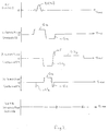
- Figure 2 is a diagram illustrating a sequence of steps carried out in the method.
- the apparatus which is a diagnostic patient imaging apparatus, includes an electromagnetic system which produces a strong uniform static magnetic field Bo across a gap between two pole pieces 1 of the electromagnet system, the pole pieces 1 being joined by a yoke (not shown) carrying an energising coil (not shown).
- a patient 3 to be imaged is placed in the gap between the pole pieces on a suitable support (not shown) so that the head-to-toe axis of the patient is orthogonal to the direction of the magnetic field Bo in the gap between the pole pieces.
- the strength of the field in the gap between the pole pieces 1, and hence in the patient 3, is controlled by a computer 5 via a main magnet control means 7 which controls the supply of energising current to the electromagnetic energising coil.
- the apparatus further includes a gradient coil system 9 whereby a gradient may be imposed on the static magnetic field in the gap between the pole pieces 1 in any one or more of three orthogonal directions x, y and z.
- the coil system 9 is energised by currents supplied by a gradient field control means 11 under control of the computer 5.
- the apparatus further includes an r.f. antenna system 13.
- the antenna system 13 is selectively connectable by way of a transmit-receive (T-R) switch 15 either to an r.f. transmitter 17 or a receiver 19.
- T-R transmit-receive
- the transmitter 17 is operated under control of the computer 5 to apply r.f. field pulses to the patient 3 for excitation of magnetic resonance in the patient 3.
- R.f. signals resulting from magnetic resonance excited in the body are sensed by the antenna system 13 and passed via the receiver 19 to an imager 21 which under control of the computer 5 processes the signals to produce signals representing an image of the patient 3.
- These signals are, in turn, passed to a display device 23 to provide a visual display of the image.
- the antenna system 13 may comprise separate transmitting and receiving coil arrangements respectively connected with transmitter 17 and receiver 19.
- the field provided by the electromagnet defines an equilibrium axis of magnetic alignment in the region of interest of the patient 3.
- an r.f. field pulse is first applied to the body by means of the r.f. transmitter 17 and antenna system 13 to excite magnetic resonance in the selected region.
- the antenna system 13 produces a field B1 in a direction orthogonal to the static field direction so as to tip the spins of nuclei in the selected region from the direction of the static field into a plane orthogonal to the static field direction.
- the r.f. field pulse is applied in conjunction with magnetic field gradients imposed by the coil system 9, the frequency of the r.f. field being chosen in conjunction with the magnitudes and directions of the imposed gradients so that the Larmor frequency of chosen protons in the body, e.g. hydrogen protons, is equal to the r.f. field frequency only in the selected region.
- the r.f. signals resulting from excitation are then spatially encoded by application of one or more further gradient magnetic fields, detected by the antenna system 13 and processed to produce an image.
- the end portions 1A of the pole pieces 1 are made of a material which does not support eddy currents.
- Suitable materials are insulated iron powders, for example, iron epoxy compositions such as those supplied by Hogänäs AB of Hogänäs, Sweden.
- each such compensating gradient has an integral which is relatively small, i.e. its duration is made as small as is practical. In some cases it may be necessary to alter the duration of the gradient pulse whose remanent magnetisation effect is being compensated so that the altered duration pulse and the corresponding compensation pulse together have a desired integral.
- an excitation and detection sequence wherein there is first applied a 90° r.f. excitation pulse B1(90) in the presence of a slice selection gradient.
- a 90° r.f. excitation pulse B1(90) for the purposes of the present example the direction of the static magnetic field in the gap between pole pieces 1 is designated the z-direction and the head-to-toe direction of the patient 3 is designated the x-direction, as illustrated in Figure 1.
- the slice selection gradient applied during r.f. pulse B1 (90) is therefore in the x-direction and designated Gx in Figure 2.
- the slice selection gradient Gx is followed immediately by a reverse gradient -Gx of the same magnitude but of appropriate shorter duration than the slice selection pulse Gx which serves to compensate in known manner for the variation in the magnetic field across the width of the selected slice during excitation.
- a phase encoding gradient Gz is applied, and during detection, i.e. data acquisition, a frequency encoding gradient G2y is applied, as shown in Figure 2, the detected signal comprising a gradient recalled echo signal.
- the excitation and detection sequence is repeated a number of times with a different value of the phase encoding gradient Gz each time.
- the gradient G2y is preceded by a reverse gradient -G1y.
- the gradients -G1y and G2y are required to exhibit different magnitudes and consequently can result in remnant y-direction magnetisation.
- a short initial portion 25 of the gradient G2y has the same magnitude as the -G1y gradient.
- phase encoding gradient is followed by a short gradient -Gz of opposite polarity to, but the same magnitude as, the phase encoding gradient Gz.
- a short gradient -G'z of the opposite polarity to, but the same magnitude as, the gradient Gz may be applied before excitation, but this requires a reduction in the duration of the gradient Gz, as illustrated by dotted lines in Figure 2. However care must be taken in this case not to distort slice selection.
Landscapes
- Physics & Mathematics (AREA)
- Condensed Matter Physics & Semiconductors (AREA)
- General Physics & Mathematics (AREA)
- Magnetic Resonance Imaging Apparatus (AREA)
Description
- This invention relates to magnetic resonance methods and apparatus.
- More particularly the invention relates to magnetic resonance methods and apparatus for the examination of an internal region of a body, for example, an internal region of the body of a live human patient for medical purposes.
- In use of such magnetic resonance methods and apparatus for examining the body of a live human patient for medical purposes, e.g. to obtain image and/or spectroscopic data, the body under investigation is placed in a homogeneous static magnetic field to define an equilibrium axis of magnetic alignment in the region of the body being examined. A radio frequency (r.f.) magnetic field is then applied to the region being examined in a direction orthogonal to the static magnetic field direction to excite magnetic resonance in material, typically in hydrogen protons, in the region, and the resulting r.f. signals are detected and analysed. During this sequence of operations one or more gradients are normally imposed on the static magnetic field to cause excitation of magnetic resonance preferentially in the region of the body to be examined, to encode spatially the detected r.f. signals, and also for other purposes such as flow encoding.
- In such methods and apparatus the static magnetic field may be applied by means of an iron-yoked permanent or electromagnet, the body to be examined being placed in a gap between opposed faces of a apir of a apir of pole pieces joined by the yoke. In such an arrangement gradients imposed on the static magnetic field are conveniently produced by coils disposed in the gap adjacent the pole pieces and lying generally in planes parallel to the opposed faces of the pole pieces.
- One problem which arises with such an arrangement is that flux from the gradient coils penetrates the pole pieces and generates eddy currents in the pole pieces. As a result, the field in the pole pieces can become locally distorted with resulting deterioration of the homogeneity of the field in the gap and hence in the body under examination.
- One way to overcome this problem is to actively shield the gradient coils so as to prevent flux from the gradient coils entering the pole pieces. However, such shielded gradient coils occupy an appreciable volume within the gap between the pole pieces with the result that, to accommodate a body of given size, the width of the gap between the pole pieces must be increased, with resulting increase in weight and cost of the magnet producing the static magnetic field.
- It is an object of the present invention to provide an alternative way of overcoming this problem.
- US-A-4,827,235 discloses a magnetic field generator useful for MRI comprising a permanent magnet, and pole pieces magnetically connected to the permanent magnet. The pole pieces are disposed to face each other to generate a magnetic field between them, and have a specific resistance of 20µΩ-cm or more. The permanent magnet comprises a sintered alloy including iron as a main component, a rare earth element including yttrium, cobalt, and boron. The permanent magnet includes, as its main part, a strong magnetic Fe-rich phase of a tetragonal system, as well as a non-magnetic Laves phase, and preferably has a maximum energy product of 38 MGOe or more.
- EP-A-0541872 discloses an MRI magnetic field generating apparatus wherein soft ferrite is arranged in the vicinity of the gradient magnetic field coils on the surfaces of static magnetic field generating permanent magnets facing the examination region.
- WO-A-91/14948 discloses an NMR scanner including a ferromagnetic frame defining a patient-receiving space adapted to receive a human body. It also includes a pair of opposed polar regions aligned on a polar axis. The polar regions are disposed on opposite sides of the patient-receiving space. Structure including either electrical windings or a permanent magnet is provided proximate each of the polar regions for producing a magnetic field within the patient-receiving space. Windings positioned in proximity to each of the polar regions are provided for producing gradients in the magnetic field, when energized. A layer of an electrically resistive but magnetically permeable material such as a ferrite, a sintered metal or a metal containing composite, is positioned in each of the polar regions for limiting eddy current generation in the polar regions when the gradient producing windings are energized. Each of the layers is oriented generally perpendicular to the polar axis.
- JP-A-2152440 discloses a scheme for correcting phase errors that arise from eddy currents in signal obtained with high speed MR imaging. An extra gradient pulse is introduced in each TR period on the frequency encoding axis. The time integral of the extra pulse is chosen to compensate for the time integral over the sequence as a whole of any eddy currents. The required time integral can be achieved by any suitable combination of amplitude(s) and duration(s).
- JP-A-6245917 discloses a scheme for addressing MRI apparatus magnetic plate hysteresis problems, and is concerned with lack of uniformity of the static magnetic field. A modification is made, at the time of readout, to the amplitude of the frequency encode gradient. This modification is an adjustment to the readout frequency encode gradient amplitude to correct for residual gradients present at the time of readout. Thus, degradation in the homogeneity of the static field is corrected for, at the time of readout, by appropriately modifying the readout frequency encode gradient amplitude. A further, phase correction is also made.
- JP-A-4129531 discloses an 'at the time' MRI correction scheme for eddy currents. The desired gradient pulses are modified to include an element that compensates for eddy currents that are active at the time of the pulse.
- According to one aspect of the present invention there is provided a magnetic resonance apparatus including a magnet system incorporating two pole pieces having opposed surfaces which define a gap in which a body to be examined is placed in use of the apparatus, the magnet system producing a static magnetic field in the gap which defines an equilibrium axis of magnetic alignment in the body, and the apparatus further including a gradient coil arrangement whereby at least one gradient may be superimposed on the magnetic field in the gap, at least the portions of said pole pieces adjacent said surfaces comprising a magnetic material which does not support eddy currents, said apparatus further including means arranged to apply, during an excitation and detection sequence, a sequence of energising currents to the gradient coil arrangement to impose a desired sequence of frequency or phase encoding gradients on the magnetic field in the gap, characterised in that said means is also arranged to control the magnitudes and polarities of the applied energising currents so that there is substantially no remanent magnetism in said material due to said field gradients at the end of the excitation and detection sequence.
- According to a second aspect of the present invention there is provided a method of examining a body using a magnetic resonance technique comprising: disposing the body in a magnetic field extending across a gap between opposed surfaces of a pair of pole pieces of a magnet system so as to define an equilibrium axis of magnetic alignment in the body, at least the portions of the pole pieces adjacent said surfaces comprising a material which does not support eddy currents; applying a radio frequency field to the body in said gap to excite magnetic resonance in said body; detecting r.f. signals emitted by the body in consequence of the excited magnetic resonance and analysing the detected signals to derive data relating to the body; and during an excitation and detection sequence, applying a sequence of energising currents to a gradient coil arrangement to impose a desired sequence of frequency or phase encoding gradients on the magnetic field in the gap, characterised by controlling the magnitudes and polarities of the applied energising currents so that there is substantially no remanent magnetism in said material due to said field gradients at the end of the excitation and detection sequence.
- One magnetic resonance apparatus and method in accordance with the invention will now be described, by way of example, with reference to the accompanying drawings in which:-
- Figure 1 is a schematic diagram of the apparatus;
- Figure 2 is a diagram illustrating a sequence of steps carried out in the method.
- Referrring to Figure 1, the apparatus, which is a diagnostic patient imaging apparatus, includes an electromagnetic system which produces a strong uniform static magnetic field Bo across a gap between two
pole pieces 1 of the electromagnet system, thepole pieces 1 being joined by a yoke (not shown) carrying an energising coil (not shown). In use of the apparatus a patient 3 to be imaged is placed in the gap between the pole pieces on a suitable support (not shown) so that the head-to-toe axis of the patient is orthogonal to the direction of the magnetic field Bo in the gap between the pole pieces. - The strength of the field in the gap between the
pole pieces 1, and hence in the patient 3, is controlled by a computer 5 via a main magnet control means 7 which controls the supply of energising current to the electromagnetic energising coil. - The apparatus further includes a
gradient coil system 9 whereby a gradient may be imposed on the static magnetic field in the gap between thepole pieces 1 in any one or more of three orthogonal directions x, y and z. Thecoil system 9 is energised by currents supplied by a gradient field control means 11 under control of the computer 5. - The apparatus further includes an r.f.
antenna system 13. Theantenna system 13 is selectively connectable by way of a transmit-receive (T-R)switch 15 either to an r.f.transmitter 17 or areceiver 19. Thetransmitter 17 is operated under control of the computer 5 to apply r.f. field pulses to the patient 3 for excitation of magnetic resonance in the patient 3. R.f. signals resulting from magnetic resonance excited in the body are sensed by theantenna system 13 and passed via thereceiver 19 to animager 21 which under control of the computer 5 processes the signals to produce signals representing an image of the patient 3. These signals are, in turn, passed to adisplay device 23 to provide a visual display of the image. Instead of using a T-R switch theantenna system 13 may comprise separate transmitting and receiving coil arrangements respectively connected withtransmitter 17 andreceiver 19. - In operation of the apparatus the field provided by the electromagnet defines an equilibrium axis of magnetic alignment in the region of interest of the patient 3.
- To obtain an image of a selected region of the patient's body, an r.f. field pulse is first applied to the body by means of the r.f.
transmitter 17 andantenna system 13 to excite magnetic resonance in the selected region. To this end theantenna system 13 produces a field B1 in a direction orthogonal to the static field direction so as to tip the spins of nuclei in the selected region from the direction of the static field into a plane orthogonal to the static field direction. To restrict excitation to the selected region the r.f. field pulse is applied in conjunction with magnetic field gradients imposed by thecoil system 9, the frequency of the r.f. field being chosen in conjunction with the magnitudes and directions of the imposed gradients so that the Larmor frequency of chosen protons in the body, e.g. hydrogen protons, is equal to the r.f. field frequency only in the selected region. - The r.f. signals resulting from excitation are then spatially encoded by application of one or more further gradient magnetic fields, detected by the
antenna system 13 and processed to produce an image. - Normally a number of excitation and signal detection sequences are required to produce sufficient data to produce a satisfactory image.
- It will be appreciated that, due to the proximity of the gradient coil system to the
pole pieces 1, gradient fields will penetrate into the pole pieces in operation of the apparatus. - In accordance with the invention, in order to prevent such penetrating fields producing significant eddy currents in the pole pieces, with resultant distortion of the magnetic field in the gap between the pole pieces and hence of the images obtained, the
end portions 1A of thepole pieces 1 are made of a material which does not support eddy currents. Suitable materials are insulated iron powders, for example, iron epoxy compositions such as those supplied by Hogänäs AB of Hogänäs, Sweden. - It will be appreciated that materials of this nature exhibit a relatively high degree of magnetic hysteresis. As a result, unless special steps are taken, a complex pattern of magnetisation can remain in the material at the end of an excitation and detection sequence which will result in degradation of the homogeneity of the static field in the gap and hence of the images obtained.
- This problem is overcome in accordance with the invention by arranging that, in the gradient magnetic field sequences, for each required gradient pulse of a particular polarity there is applied a compensating pulse of the same magnitude, but the opposite polarity. By this means the production of remanent magnetism in the
end portions 1A of the pole pieces is substantially avoided. In order to otherwise minimise its effect each such compensating gradient has an integral which is relatively small, i.e. its duration is made as small as is practical. In some cases it may be necessary to alter the duration of the gradient pulse whose remanent magnetisation effect is being compensated so that the altered duration pulse and the corresponding compensation pulse together have a desired integral. - Referring now to Figure 2, in one particular method in accordance with the invention for producing images using a two-dimensional Fourier transformation technique, there is used an excitation and detection sequence wherein there is first applied a 90° r.f. excitation pulse B1(90) in the presence of a slice selection gradient. For the purposes of the present example the direction of the static magnetic field in the gap between
pole pieces 1 is designated the z-direction and the head-to-toe direction of the patient 3 is designated the x-direction, as illustrated in Figure 1. The slice selection gradient applied during r.f. pulse B1 (90) is therefore in the x-direction and designated Gx in Figure 2. The slice selection gradient Gx is followed immediately by a reverse gradient -Gx of the same magnitude but of appropriate shorter duration than the slice selection pulse Gx which serves to compensate in known manner for the variation in the magnetic field across the width of the selected slice during excitation. - Since the pulses Gx and -Gx are of equal magnitude and opposite polarity, no further compensating pulse to prevent x-direction remnant magnetisation in accordance with the invention is required.
- After excitation but before detection, e.g. during application of gradient -Gx, a phase encoding gradient Gz is applied, and during detection, i.e. data acquisition, a frequency encoding gradient G2y is applied, as shown in Figure 2, the detected signal comprising a gradient recalled echo signal. To obtain a full set of data for an image, the excitation and detection sequence is repeated a number of times with a different value of the phase encoding gradient Gz each time. In order to ensure, in known manner, that the detected echo signal occurs at the intended time during the gradient G2y the gradient G2y is preceded by a reverse gradient -G1y.
- The gradients -G1y and G2y are required to exhibit different magnitudes and consequently can result in remnant y-direction magnetisation. To prevent this in accordance with the invention, a short
initial portion 25 of the gradient G2y has the same magnitude as the -G1y gradient. - Similarly, to prevent z-direction remanent magnetisation resulting from the phase encoding gradient Gz the phase encoding gradient is followed by a short gradient -Gz of opposite polarity to, but the same magnitude as, the phase encoding gradient Gz. Alternatively, if the hysteresis effect is not very large, a short gradient -G'z of the opposite polarity to, but the same magnitude as, the gradient Gz may be applied before excitation, but this requires a reduction in the duration of the gradient Gz, as illustrated by dotted lines in Figure 2. However care must be taken in this case not to distort slice selection.
Claims (6)
- A magnetic resonance apparatus including a magnet system incorporating two pole pieces (1) having opposed surfaces which define a gap in which a body (3) to be examined is placed in use of the apparatus, the magnet system producing a static magnetic field in the gap which defines an equilibrium axis of magnetic alignment in the body (3), and the apparatus further including a gradient coil arrangement (9) whereby at least one gradient may be superimposed on the magnetic field in the gap, at least the portions (1A) of said pole pieces (1) adjacent said surfaces comprising a magnetic material which does not support eddy currents, said apparatus further including means (5, 11) arranged to apply, during an excitation and detection sequence, a sequence of energising currents to the gradient coil arrangement (9) to impose a desired sequence of frequency or phase encoding gradients on the magnetic field in the gap, characterised in that said means (5, 11) is also arranged to control the magnitudes and polarities of the applied energising currents so that there is substantially no remanent magnetism in said material due to said field gradients at the end of the excitation and detection sequence.
- An apparatus according to Claim 1 wherein said magnetic material comprises an insulated iron powder.
- An apparatus according to Claim 2 wherein said magnetic material comprises an iron/epoxy composition.
- A method of examining a body (3) using a magnetic resonance technique comprising: disposing the body (3) in a magnetic field extending across a gap between opposed surfaces of a pair of pole pieces (1) of a magnet system so as to define an equilibrium axis of magnetic alignment in the body (3), at least the portions (1A) of the pole pieces (1) adjacent said surfaces comprising a material which does not support eddy currents; applying a radio frequency field to the body (3) in said gap to excite magnetic resonance in said body (3); detecting r.f. signals emitted by the body (3) in consequence of the excited magnetic resonance and analysing the detected signals to derive data relating to the body (3); and during an excitation and detection sequence, applying a sequence of energising currents to a gradient coil arrangement (9) to impose a desired sequence of frequency or phase encoding gradients on the magnetic field in the gap, characterised by controlling the magnitudes and polarities of the applied energising currents so that there is substantially no remanent magnetism in said material due to said field gradients at the end of the excitation and detection sequence.
- A method according to Claim 4 wherein the magnitudes of the applied energising currents are controlled so that in said sequence of gradients, for each imposed gradient of a particular polarity there is applied a compensating gradient of substantially the same magnitude but the opposite polarity.
- A method according to Claim 5 wherein the or each said compensating gradient is of relatively short duration compared with any other gradient applied during said sequence of gradients.
Applications Claiming Priority (2)
| Application Number | Priority Date | Filing Date | Title |
|---|---|---|---|
| GB9513544 | 1995-07-04 | ||
| GBGB9513544.8A GB9513544D0 (en) | 1995-07-04 | 1995-07-04 | Magnetic resonance methods and apparatus |
Publications (3)
| Publication Number | Publication Date |
|---|---|
| EP0752596A2 EP0752596A2 (en) | 1997-01-08 |
| EP0752596A3 EP0752596A3 (en) | 1997-04-16 |
| EP0752596B1 true EP0752596B1 (en) | 2000-08-30 |
Family
ID=10777065
Family Applications (1)
| Application Number | Title | Priority Date | Filing Date |
|---|---|---|---|
| EP96304893A Expired - Lifetime EP0752596B1 (en) | 1995-07-04 | 1996-07-03 | Magnetic resonance methods and apparatus |
Country Status (5)
| Country | Link |
|---|---|
| US (1) | US5675256A (en) |
| EP (1) | EP0752596B1 (en) |
| JP (1) | JPH0924037A (en) |
| DE (1) | DE69610044T2 (en) |
| GB (1) | GB9513544D0 (en) |
Families Citing this family (11)
| Publication number | Priority date | Publication date | Assignee | Title |
|---|---|---|---|---|
| US5869970A (en) * | 1995-10-31 | 1999-02-09 | Cardiac Pacemakers, Inc. | Power management system for an implantable device |
| US5864233A (en) * | 1997-02-22 | 1999-01-26 | General Electric Company | Method to reduce eddy current effects in diffusion-weighted echo planar imaging |
| US6272370B1 (en) | 1998-08-07 | 2001-08-07 | The Regents Of University Of Minnesota | MR-visible medical device for neurological interventions using nonlinear magnetic stereotaxis and a method imaging |
| US6463317B1 (en) | 1998-05-19 | 2002-10-08 | Regents Of The University Of Minnesota | Device and method for the endovascular treatment of aneurysms |
| JP3453089B2 (en) * | 1999-08-20 | 2003-10-06 | ジーイー横河メディカルシステム株式会社 | MRI equipment |
| JP4369613B2 (en) * | 2000-11-20 | 2009-11-25 | 株式会社日立メディコ | Magnetic resonance imaging system |
| DE10063676B4 (en) | 2000-12-20 | 2006-08-17 | Siemens Ag | Multi-echo imaging method |
| US6822451B2 (en) * | 2002-07-31 | 2004-11-23 | Ge Medical Systems Global Technology Company Llc | Non-coupling magnetic sheilding coil |
| EP1647224B1 (en) * | 2003-07-17 | 2012-06-06 | Hitachi Medical Corporation | Magnetic resonance imaging method and system |
| CN106669040B (en) * | 2016-12-29 | 2019-08-23 | 臧大维 | Stereotactic magnetic head and array, brain nerve cell electrical activity interference system |
| EP4019995B1 (en) * | 2020-12-22 | 2023-08-16 | Bruker BioSpin GmbH | Epr spectrometer with at least one pole piece made at least partially of a function material |
Family Cites Families (14)
| Publication number | Priority date | Publication date | Assignee | Title |
|---|---|---|---|---|
| US4827235A (en) * | 1986-07-18 | 1989-05-02 | Kabushiki Kaisha Toshiba | Magnetic field generator useful for a magnetic resonance imaging instrument |
| US5063934A (en) * | 1987-10-07 | 1991-11-12 | Advanced Techtronics, Inc. | Permanent magnet arrangement |
| JPH02109542A (en) * | 1988-10-18 | 1990-04-23 | Yokogawa Medical Syst Ltd | Method for decreasing influence of eddy current by magnetic field gradient of mri |
| JPH02152440A (en) * | 1988-12-02 | 1990-06-12 | Mitsubishi Electric Corp | Magnetic resonance imaging method |
| JPH02264636A (en) * | 1988-12-23 | 1990-10-29 | Picker Internatl Ltd | Nuclear magnetic resonance method |
| JP2860682B2 (en) * | 1990-02-09 | 1999-02-24 | 株式会社日立メディコ | Method for stabilizing static magnetic field uniformity of magnetic resonance imaging apparatus |
| US5061897A (en) * | 1990-03-23 | 1991-10-29 | Fonar Corporation | Eddy current control in magnetic resonance imaging |
| JPH04129531A (en) * | 1990-09-20 | 1992-04-30 | Toshiba Corp | Magnetic resonance imaging |
| US5304932A (en) * | 1990-11-05 | 1994-04-19 | The Regents Of The University Of California | Apparatus and method for shielding MRI RF antennae from the effect of surrounding objects |
| DE69131940T2 (en) * | 1991-11-15 | 2000-08-17 | Hitachi Medical Corp., Tokio/Tokyo | Apparatus for generating magnetic fields for imaging by means of magnetic resonance |
| DE4203036C2 (en) * | 1992-02-04 | 1994-04-14 | Bruker Medizintech | Method for generating a sideband-free NMR spectrum |
| US5495171A (en) * | 1993-01-19 | 1996-02-27 | Fonar Corporation | Eddy current control in NMR imaging systems |
| JPH06245917A (en) * | 1993-02-23 | 1994-09-06 | Yokogawa Medical Syst Ltd | Mri equipment |
| FI105293B (en) * | 1993-06-08 | 2000-07-14 | Picker Nordstar Oy | Polsko for a magnet used in magnetic resonance imaging |
-
1995
- 1995-07-04 GB GBGB9513544.8A patent/GB9513544D0/en active Pending
-
1996
- 1996-07-02 US US08/674,504 patent/US5675256A/en not_active Expired - Fee Related
- 1996-07-03 EP EP96304893A patent/EP0752596B1/en not_active Expired - Lifetime
- 1996-07-03 DE DE69610044T patent/DE69610044T2/en not_active Expired - Fee Related
- 1996-07-03 JP JP8192941A patent/JPH0924037A/en active Pending
Also Published As
| Publication number | Publication date |
|---|---|
| JPH0924037A (en) | 1997-01-28 |
| GB9513544D0 (en) | 1995-09-06 |
| EP0752596A3 (en) | 1997-04-16 |
| DE69610044D1 (en) | 2000-10-05 |
| DE69610044T2 (en) | 2002-03-21 |
| US5675256A (en) | 1997-10-07 |
| EP0752596A2 (en) | 1997-01-08 |
Similar Documents
| Publication | Publication Date | Title |
|---|---|---|
| US7027853B2 (en) | Data acquisition method and apparatus for MR imaging | |
| US6650118B2 (en) | RF coil system for an MR apparatus | |
| US6507190B1 (en) | Method and apparatus for compensating polarizing fields in magnetic resonance imaging | |
| JPH0638943A (en) | Magnetic resonance imaging system and magnetic resonance imaging method | |
| JPH0856928A (en) | Mr modulus that determines core magnetization distribution by surface coil setting | |
| JPH11342121A (en) | Shim coil magnetic resonance imaging system | |
| US7541811B2 (en) | Apparatus for electron spin resonance CT | |
| KR20000047676A (en) | A method for compensating an mri system for residual magnetization | |
| US5675256A (en) | Magnetic resonance methods and apparatus | |
| US6498947B2 (en) | rf shielding method and apparatus | |
| EP0913699B1 (en) | Planar gradient coil system for MRI positioned on only one side of the subject to be examined | |
| US7199585B2 (en) | Method for shimming a main magnetic field in magnetic resonance | |
| KR100413904B1 (en) | Selective excitation method and apparatus, and magnetic resonance imaging method and apparatus | |
| US4876508A (en) | Method and apparatus for NMR imaging | |
| EP0097519B1 (en) | Nuclear magnetic resonance diagnostic apparatus | |
| EP0982599B1 (en) | Magnetic resonance imaging magnet system | |
| US5451875A (en) | Technique for reducing aliasing artifacts wtih insertable gradient coils | |
| US6850066B2 (en) | Systems and methods for gradient compensation in magnetic resonance imaging | |
| US10935615B2 (en) | Magnetic resonance imaging with spatial encoding by fast moving or vibrating magnetic field generator components | |
| WO2003096046A1 (en) | Magnetic resonance imaging | |
| US5329232A (en) | Magnetic resonance methods and apparatus | |
| US6294916B1 (en) | NMR and ESR probes for closed loop control of gradient fields | |
| JPS6267433A (en) | Nmr imaging apparatus | |
| US20250199100A1 (en) | Improved low field magnetic resonance imaging instrumental system and methods of use | |
| Pavlicek | MR instrumentation and image formation. |
Legal Events
| Date | Code | Title | Description |
|---|---|---|---|
| PUAI | Public reference made under article 153(3) epc to a published international application that has entered the european phase |
Free format text: ORIGINAL CODE: 0009012 |
|
| AK | Designated contracting states |
Kind code of ref document: A2 Designated state(s): DE FR NL |
|
| PUAL | Search report despatched |
Free format text: ORIGINAL CODE: 0009013 |
|
| AK | Designated contracting states |
Kind code of ref document: A3 Designated state(s): DE FR NL |
|
| 17P | Request for examination filed |
Effective date: 19971003 |
|
| 17Q | First examination report despatched |
Effective date: 19980902 |
|
| GRAG | Despatch of communication of intention to grant |
Free format text: ORIGINAL CODE: EPIDOS AGRA |
|
| GRAG | Despatch of communication of intention to grant |
Free format text: ORIGINAL CODE: EPIDOS AGRA |
|
| GRAH | Despatch of communication of intention to grant a patent |
Free format text: ORIGINAL CODE: EPIDOS IGRA |
|
| GRAH | Despatch of communication of intention to grant a patent |
Free format text: ORIGINAL CODE: EPIDOS IGRA |
|
| GRAA | (expected) grant |
Free format text: ORIGINAL CODE: 0009210 |
|
| RAP1 | Party data changed (applicant data changed or rights of an application transferred) |
Owner name: BAE SYSTEMS ELECTRONICS LTD. |
|
| AK | Designated contracting states |
Kind code of ref document: B1 Designated state(s): DE FR NL |
|
| REF | Corresponds to: |
Ref document number: 69610044 Country of ref document: DE Date of ref document: 20001005 |
|
| ET | Fr: translation filed | ||
| PLBE | No opposition filed within time limit |
Free format text: ORIGINAL CODE: 0009261 |
|
| STAA | Information on the status of an ep patent application or granted ep patent |
Free format text: STATUS: NO OPPOSITION FILED WITHIN TIME LIMIT |
|
| 26N | No opposition filed | ||
| PG25 | Lapsed in a contracting state [announced via postgrant information from national office to epo] |
Ref country code: NL Free format text: LAPSE BECAUSE OF NON-PAYMENT OF DUE FEES Effective date: 20020201 |
|
| PG25 | Lapsed in a contracting state [announced via postgrant information from national office to epo] |
Ref country code: FR Free format text: LAPSE BECAUSE OF NON-PAYMENT OF DUE FEES Effective date: 20020329 |
|
| NLV4 | Nl: lapsed or anulled due to non-payment of the annual fee |
Effective date: 20020201 |
|
| PG25 | Lapsed in a contracting state [announced via postgrant information from national office to epo] |
Ref country code: DE Free format text: LAPSE BECAUSE OF NON-PAYMENT OF DUE FEES Effective date: 20020501 |
|
| REG | Reference to a national code |
Ref country code: FR Ref legal event code: ST |