EP0750930A1 - Process and apparatus for dedusting a stream of crude gas and/or for sorbing gaseous compounds from the crude gas stream - Google Patents
Process and apparatus for dedusting a stream of crude gas and/or for sorbing gaseous compounds from the crude gas stream Download PDFInfo
- Publication number
- EP0750930A1 EP0750930A1 EP96109359A EP96109359A EP0750930A1 EP 0750930 A1 EP0750930 A1 EP 0750930A1 EP 96109359 A EP96109359 A EP 96109359A EP 96109359 A EP96109359 A EP 96109359A EP 0750930 A1 EP0750930 A1 EP 0750930A1
- Authority
- EP
- European Patent Office
- Prior art keywords
- reactor
- cylinder wall
- raw gas
- perforated cylinder
- gas stream
- Prior art date
- Legal status (The legal status is an assumption and is not a legal conclusion. Google has not performed a legal analysis and makes no representation as to the accuracy of the status listed.)
- Withdrawn
Links
Images


Classifications
-
- B—PERFORMING OPERATIONS; TRANSPORTING
- B01—PHYSICAL OR CHEMICAL PROCESSES OR APPARATUS IN GENERAL
- B01D—SEPARATION
- B01D46/00—Filters or filtering processes specially modified for separating dispersed particles from gases or vapours
- B01D46/02—Particle separators, e.g. dust precipitators, having hollow filters made of flexible material
- B01D46/04—Cleaning filters
-
- B—PERFORMING OPERATIONS; TRANSPORTING
- B01—PHYSICAL OR CHEMICAL PROCESSES OR APPARATUS IN GENERAL
- B01D—SEPARATION
- B01D46/00—Filters or filtering processes specially modified for separating dispersed particles from gases or vapours
- B01D46/24—Particle separators, e.g. dust precipitators, using rigid hollow filter bodies
-
- B—PERFORMING OPERATIONS; TRANSPORTING
- B01—PHYSICAL OR CHEMICAL PROCESSES OR APPARATUS IN GENERAL
- B01D—SEPARATION
- B01D46/00—Filters or filtering processes specially modified for separating dispersed particles from gases or vapours
- B01D46/56—Filters or filtering processes specially modified for separating dispersed particles from gases or vapours with multiple filtering elements, characterised by their mutual disposition
- B01D46/62—Filters or filtering processes specially modified for separating dispersed particles from gases or vapours with multiple filtering elements, characterised by their mutual disposition connected in series
- B01D46/64—Filters or filtering processes specially modified for separating dispersed particles from gases or vapours with multiple filtering elements, characterised by their mutual disposition connected in series arranged concentrically or coaxially
-
- B—PERFORMING OPERATIONS; TRANSPORTING
- B01—PHYSICAL OR CHEMICAL PROCESSES OR APPARATUS IN GENERAL
- B01D—SEPARATION
- B01D46/00—Filters or filtering processes specially modified for separating dispersed particles from gases or vapours
- B01D46/66—Regeneration of the filtering material or filter elements inside the filter
- B01D46/70—Regeneration of the filtering material or filter elements inside the filter by acting counter-currently on the filtering surface, e.g. by flushing on the non-cake side of the filter
-
- B—PERFORMING OPERATIONS; TRANSPORTING
- B01—PHYSICAL OR CHEMICAL PROCESSES OR APPARATUS IN GENERAL
- B01D—SEPARATION
- B01D53/00—Separation of gases or vapours; Recovering vapours of volatile solvents from gases; Chemical or biological purification of waste gases, e.g. engine exhaust gases, smoke, fumes, flue gases, aerosols
- B01D53/02—Separation of gases or vapours; Recovering vapours of volatile solvents from gases; Chemical or biological purification of waste gases, e.g. engine exhaust gases, smoke, fumes, flue gases, aerosols by adsorption, e.g. preparative gas chromatography
- B01D53/06—Separation of gases or vapours; Recovering vapours of volatile solvents from gases; Chemical or biological purification of waste gases, e.g. engine exhaust gases, smoke, fumes, flue gases, aerosols by adsorption, e.g. preparative gas chromatography with moving adsorbents, e.g. rotating beds
- B01D53/10—Separation of gases or vapours; Recovering vapours of volatile solvents from gases; Chemical or biological purification of waste gases, e.g. engine exhaust gases, smoke, fumes, flue gases, aerosols by adsorption, e.g. preparative gas chromatography with moving adsorbents, e.g. rotating beds with dispersed adsorbents
-
- B—PERFORMING OPERATIONS; TRANSPORTING
- B01—PHYSICAL OR CHEMICAL PROCESSES OR APPARATUS IN GENERAL
- B01D—SEPARATION
- B01D53/00—Separation of gases or vapours; Recovering vapours of volatile solvents from gases; Chemical or biological purification of waste gases, e.g. engine exhaust gases, smoke, fumes, flue gases, aerosols
- B01D53/34—Chemical or biological purification of waste gases
- B01D53/46—Removing components of defined structure
- B01D53/48—Sulfur compounds
- B01D53/50—Sulfur oxides
- B01D53/508—Sulfur oxides by treating the gases with solids
-
- B—PERFORMING OPERATIONS; TRANSPORTING
- B01—PHYSICAL OR CHEMICAL PROCESSES OR APPARATUS IN GENERAL
- B01D—SEPARATION
- B01D53/00—Separation of gases or vapours; Recovering vapours of volatile solvents from gases; Chemical or biological purification of waste gases, e.g. engine exhaust gases, smoke, fumes, flue gases, aerosols
- B01D53/34—Chemical or biological purification of waste gases
- B01D53/74—General processes for purification of waste gases; Apparatus or devices specially adapted therefor
- B01D53/81—Solid phase processes
- B01D53/83—Solid phase processes with moving reactants
-
- B—PERFORMING OPERATIONS; TRANSPORTING
- B01—PHYSICAL OR CHEMICAL PROCESSES OR APPARATUS IN GENERAL
- B01D—SEPARATION
- B01D2267/00—Multiple filter elements specially adapted for separating dispersed particles from gases or vapours
- B01D2267/40—Different types of filters
Definitions
- the invention relates to a method for dedusting a raw gas stream and / or sorption of gaseous substances from the raw gas stream by adding dry adsorbents and / or by adding dry absorbent in a vertically arranged and circularly delimited reactor, in which the raw gas stream separates the reactor from Flows through upwards, whereby the raw gas stream is brought into contact with the dry adsorbents and / or with the dry absorbent and the raw gas stream is then passed through a bag filter which surrounds the reactor in a circle, and onto a device for carrying out the method, consisting of a center vertically arranged, circularly delimited reactor, a bag filter arranged in a circle around the reactor with filter bags arranged perpendicular to the axis parallel to the reactor, the upper end of the reactor being arranged lower than the gas outlet of the bag filter.
- DE-PS 40 29 395 describes a method and a device for the adsorption or chemisorption of gaseous substances from a raw gas stream by adding dry adsorbents or adsorbents, possibly with properties which bring about a chemical reaction with the adsorbing gas components, wherein the raw gas and the fresh adsorbent are fed to a separator system with several fabric filter chambers designed as bag filters.
- the device for performing the method exists consisting of several fabric filter chambers, each of which represents a separate bag filter.
- the individual filter bags are arranged around a central free space in each fabric filter chamber.
- the dust collected in a bunker is removed from the device via an outlet lock in the lower part of the raw gas duct. It is disadvantageous that several fabric filter chambers have to be arranged next to one another in a relatively complex construction and a uniform loading of the individual filter bags in the respective fabric filter chambers is not guaranteed. In addition, it is disadvantageous that the device described must have a relatively large amount of space, which is only available in the rarest of cases.
- a round-shaped bag filter which is used for dedusting the raw gas stream.
- the individual filter bags are arranged side by side on circular paths.
- the housing of the bag filter consists of a cylindrical jacket.
- In the middle of the bag filter there is a cavity into which a vertically arranged guide shaft protrudes, on which an arm with nozzles, which can be rotated horizontally directly above the filter bags, is arranged, through which purge air can be passed to clean several filter bags.
- the sorption of gaseous substances from a raw gas stream is not possible in this bag filter.
- the invention has for its object to provide a method for dedusting the raw gas stream and / or sorption of gaseous substances from the raw gas stream, in which the dedusting is carried out with the aid of a bag filter, the individual filter bags over their length relative are evenly charged with the crude gas stream which has already been pretreated in the reactor.
- the invention is also based on the object of providing an apparatus for carrying out the method.
- the object on which the invention is based is achieved in that the raw gas stream, after leaving the reactor, is first passed through a perforated cylinder wall and then to the filter bags of the bag filter.
- the perforated cylinder wall can be designed in many ways. For example, it can consist of a sheet metal that has circular or angular passage openings. It can be designed as a multi-layer wire mesh or consist of individual angle profiles which are not connected to one another, the raw gas stream which has already been pretreated in the reactor flowing between the individual angle profiles and then reaching the filter bags.
- Activated carbon or hearth furnace coke for example, are used as dry adsorbents.
- Ca (OH) 2 or Na 2 CO 3 for example, are used as absorbents.
- adsorbents and / or absorbents depends on the respective pollutants in the raw gas stream. It has surprisingly been found that the pretreated raw gas stream emerging from the reactor at the top is advantageously deflected downwards when it hits the perforated cylinder wall and initially flows downwards on the perforated cylinder wall, with a continuous passage of a portion of the pretreated at the same time Raw gas flow through the perforated cylinder wall. In this way it is possible to apply the pretreated raw gas stream relatively evenly over the entire length of the individual filter bags.
- a preferred embodiment of the invention is that the raw gas flow is deflected upwards or downwards when flowing through the perforated cylinder wall. If the raw gas flow is deflected upwards, the perforated cylinder wall acts to an increased extent as an impact separator, which is particularly advantageous if the dust particles are relatively large, which can result in damage to the filter bags due to abrasion. However, if the dust particles are relatively small, it is advantageous to separate the much larger amount of dust in the bag filter. For this purpose, the raw gas flow is diverted downward, so that it is ensured that the dust particles are almost completely entrained and passed to the filter bags, at the same time a better utilization of the absorbents is possible.
- the entire amount of dust and / or dry adsorbents and / or dry absorbent deposited on the perforated cylinder wall and in the bag filter is, if necessary after cleaning the perforated cylinder wall and / or after cleaning the individual filter bags, into one below the perforated one Cylinder wall and collection bunker arranged below the filter bags.
- the dry adsorbents are also to be understood as the at least partially already acted on adsorbate.
- the dust adhering to the perforated cylinder wall and separated from the individual filter bags thus reaches a common collecting bunker, which generally has a conical boundary.
- the separated amount of dust and / or dry adsorbents and / or dry is transferred into the collecting bunker
- Absorbent is fed via a conveyor trough into an intermediate bunker arranged to the side of the reactor outside of the reactor and outside of the bag filter and at least partially passed through a metering device arranged under the intermediate bunker into the inlet port of the reactor for the raw gas stream and brought back into contact with the raw gas stream, the amount of dust and / or dry adsorbents and / or dry absorbent not re-added to the raw gas stream is discharged from the intermediate bunker via a lock.
- This measure has the advantage that the adsorbents which are not fully contaminated are brought into contact again with the raw gas stream and can thereby be completely converted into adsorbate. In this way, the amount of adsorbents to be used can be minimized.
- the object on which the invention is based is also achieved by a device for carrying out the method, in which a perforated cylinder wall is arranged perpendicularly around the reactor between the reactor and those filter bags which are arranged closest to the reactor.
- the perforated cylinder wall is advantageously fixed to the ceiling of the bag filter.
- the perforated cylinder wall has through-openings for the pretreated raw gas flow, which reaches the individual filter bags behind the perforated cylinder wall.
- the length of the perforated cylinder wall corresponds to the length of the filter bags.
- the perforated cylinder wall consists of a plurality of isosceles angle profiles which are not connected to one another and which are arranged vertically in a circle around the reactor and are each connected to the ceiling of the bag filter, the ends of the legs of each angle profile facing the reactor are and have the same distance x from the reactor and the free distance a between two immediately adjacent angle profiles is 20 to 200 mm.
- the arrangement of the perforated cylinder wall made of commercially available angle profiles enables an arrangement in a relatively simple manner.
- the cleaning of the individual angular profiles of the perforated cylinder wall is advantageously carried out by tapping.
- the ends of the legs of each angle profile face the reactor and have the same distance x from the reactor.
- each individual angle profile acts as an impact separator, which is advantageous when there is a risk of damage to the filter bags due to abrasion due to the large particle size of the individual dust particles. If the free distance a between two immediately adjacent angle profiles is 20 to 200 mm, it is ensured that the filter bags are evenly treated with pretreated raw gas.
- the perforated cylinder wall consists of plate-shaped elements connected to one another on the longitudinal edges, which are arranged together in the form of a regular n-corner around the reactor and have through openings whose height or diameter b is 20 to 220 mm.
- 8 to 12 plate-shaped elements form the circular perforated cylinder wall arranged in the form of an octagon or 12 corner.
- the perforated cylinder wall can be produced in a structurally simple and quick manner, since each individual plate-shaped element can be provided with through openings in a simple manner beforehand and the plate-shaped elements then only have to be arranged in the form of an n-corner.
- Sheets are generally used as plate-shaped elements, which are welded to one another at their longitudinal edges.
- the through openings have tabs at their upper and / or lower boundaries which are bent toward the filter bags, the obtuse bending angle ⁇ being in the range from 105 to 165 ° and the width c of each tab 20 up to 200 mm and the length d of each tab is at least 50 mm. If the bending angle ⁇ is in the range from 105 to 165 °, it is ensured that the raw gas flow is deflected upwards or downwards when flowing through the perforated cylinder wall.
- the perforated cylinder wall is arranged inclined from the top to the filter bags, the acute angle of inclination ⁇ being in the range from 3 to 30 °.
- a collecting bunker with dust discharge is arranged in a circle below the perforated cylinder wall and below the filter bags around the reactor.
- the collecting bunker has a conveying trough in the lower part as dust discharge, which is connected to an intermediate bunker arranged laterally next to the reactor, which has a lock. This advantageously facilitates the removal of dust, adsorbent and adsorbate that takes place via the lock.
- a metering device is arranged between the intermediate bunker and the inlet port of the reactor. This enables the return of the adsorbent still present in the intermediate bunker or the return of the absorbent not yet loaded into the raw gas stream, so that the amount of adsorbent or absorbent to be used can be minimized.
- the metering device has a feed point for dry adsorbents and / or dry absorbents.
- dry adsorbents and / or dry ones Absorbent can be supplied to the raw gas stream relatively easily and quickly.
- the amount of dry adsorbents and / or dry absorbents to be used can be varied at the point of application and thus can be adapted to fluctuating conditions in the raw gas stream.
- a centrally vertically arranged, circularly delimited reactor (1) and a bag filter arranged in a circle around the reactor (1) are shown in longitudinal section.
- the raw gas stream passes through the inlet connection (14) into the reactor (1) and flows through the reactor (1) in the direction of the arrow from bottom to top.
- the upper end (3) of the reactor (1) is arranged lower than the gas outlet (5) of the bag filter, so that the pretreated raw gas stream can exit at the upper end (3) of the reactor (1).
- the pretreated raw gas stream After leaving the reactor (1), the pretreated raw gas stream reaches the perforated cylinder wall (4) and is deflected downwards in the direction of the arrow.
- the pretreated raw gas stream now flows downward on the perforated cylinder wall (4), partial quantities of the pretreated raw gas stream flowing through the perforated cylinder wall (4) and then being passed to the filter bags (20) of the bag filter.
- the clean gas which has been freed of dust and pollutants, is passed from the bag filter into a clean gas chamber (6) at the gas outlet (5) of the bag filter and reaches the atmosphere via the clean gas connector (7).
- the dust falls down in the interspaces (8, 9) and gets into the circular arrangement under the reactor (1) Collection bunker (10).
- the separated amount of solids entered in the collecting bunker (10) is conveyed via a conveyor trough (11) into an intermediate bunker arranged outside of the reactor (1) and outside of the bag filter laterally next to the reactor (1) (12) and at least partially passed via a metering device (13) arranged under the intermediate bunker (12) into the inlet port (14) of the reactor (1) for the raw gas stream and brought back into contact with the raw gas stream.
- the quantity of dust and / or dry adsorbents and / or dry absorbent that is not fed back into the raw gas stream is discharged from the intermediate bunker (12) via a lock (15).
- the metering device (13) has a feed point (19) for dry adsorbents and / or dry absorbents.
- a rotating arm (18) is arranged above the gas outlet (5) of the bag filter and is rotatably mounted on a shaft (17).
- the shaft (17) is rotated by the drive (16).
- a device for supplying purge gas (not shown), with which purge gas can be supplied to the rotating arm (18) for cleaning the filter bags (20).
- purge gas not shown
- those filter bags (20) each of which is located under the rotating arm (18)
- there is a brief interruption in the flow of the pretreated raw gas stream and purge gas enters these filter bags (20) from above, so that the filter bags held by the support body (20) inflate abruptly. This leads to the brief cleaning of the filter bags (20) from dust that falls into the collecting bunker (10).
- FIG. 2a, 2b the detail "Y” according to FIG. 1 is shown with the associated top view.
- FIG. 2a shows the detail "Y” according to section BB in FIG. 2a.
- the detail "Y” shows a perforated cylinder wall (4), which consists of a plurality of isosceles angle profiles which are not connected to one another and which are arranged vertically in a circle around the reactor (1) and are each connected to the ceiling of the bag filter, the ends of the legs of each angle profile facing the reactor (1) and from the reactor (1) have the same distance x, as shown in Fig. 2b.
- the free distance a between two immediately adjacent angle profiles is advantageously chosen in the range from 20 to 200 mm.
- the perforated cylinder wall (4) which consists of several isosceles angle profiles that are not connected to one another, is arranged between the reactor (1) and those filter bags (20) that are arranged closest to the reactor (1).
- the perforated cylinder wall (4) consisting of the isosceles angle profiles, it is not absolutely necessary that the longitudinal axis of each angle profile runs parallel to the longitudinal axis of the reactor (1).
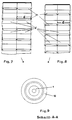
- FIG. 3 the detail “Z” is shown in FIG. 1.
- the detail “Z” shows the design of a perforated cylinder wall (4) which does not consist of several isosceles angle profiles which are not connected to one another.
- the joint representation of the detail "Y” with the detail “Z” in FIG. 1 was chosen only for reasons of clarity.
- the perforated cylinder wall (4) has a uniform design.
- FIG. 3 also shows a perforated cylinder wall (4). shown, the longitudinal axis of which corresponds to the longitudinal axis of the reactor (1).
- the perforated cylinder wall (4) it is also more advantageous in some cases to arrange the perforated cylinder wall (4) at an angle from the top to the filter bags (20), the acute angle of inclination ⁇ being in the range from 3 to 30 °. 3 shows both variants, but in practice only one is implemented.
- the perforated cylinder wall (4) shown in Fig. 3 consists of plate-shaped elements connected to each other on the longitudinal edges, which are arranged together in the form of a regular n-corner around the reactor (1) and have the passage openings (4 '), their height or Diameter b is 20 to 220 mm.
- the passage openings (4 ') have tabs (21) at their lower boundaries, which are bent towards the filter bags (20), the obtuse bending angle ⁇ being in the range from 105 to 165 °.
- the width c of each tab is 20 to 200 mm.
- the length d (not shown) of each tab is at least 50 mm.
- FIG. 4 shows a further detail "Z" according to FIG. 1, the through openings (4 '), in contrast to the illustration in FIG. 3, having tabs (21) at their upper boundaries which lead to the filter bags (20) are turned.
- the structural design of the perforated cylinder wall (4), shown in Fig. 4 will be chosen when the dust to be separated has a relatively large particle size and there is a risk that the filter bags can be destroyed by abrasion.
- the perforated cylinder wall (4) shown in Fig. 4 acts to an increased extent as an impact separator, since even those dust particles that hit the tabs (21) do not reach the filter bags (20), but down into the Collection bunker (10) fall.
- the embodiment of the perforated cylinder wall (4) shown in FIG. 3 should be selected in an advantageous manner, since the particles flowing against the tabs (21) are entrained by the gas stream and to the filter bags ( 20) arrive. Occasionally, it may be advantageous to combine the embodiments shown in FIGS. 3 and 4 with one another.
- FIG. 5 shows the top view according to section C-C in FIG. 3.
- the perforated cylinder wall consists of plate-shaped elements which are connected to one another at the longitudinal edges and which are arranged together in the form of a regular octagon around the reactor (1).
- the tabs (21) are arranged at the lower boundaries of the passage openings and bent towards the filter bags (not shown).
- FIG. 6 shows the top view according to section D-D in FIG. 4.
- the tabs (21) shown in FIG. 6 are arranged at the upper boundaries of the passage openings and are also bent toward the filter bags (not shown).
- FIG. 7 shows part of the perforated cylinder wall (4) in the direction of the arrow in FIG. 5.
- Two plate-shaped elements are connected to each other on the longitudinal edges.
- FIG. 8 shows part of the perforated cylinder wall (4) in the direction of the arrow according to FIG. 6.
- the adjacent plate-shaped ones shown in FIGS. 7 and 8 For reasons of clarity, elements are shown as if two plate-shaped elements were arranged in one plane.
- the tabs (21) have a width d that decreases in the direction of the filter bags (not shown), but this is not absolutely necessary.
- a collecting bunker (10) is arranged in a circle around the reactor (1) and has a conveyor trough (11) (not shown) in the lower part.
- the amount of exhaust gas from a raw gas is 135,000 Nm 3 / h, the raw gas having a temperature of 100 ° C, a dew point of 51 ° C and a dust content of 30 g / Nm 3 .
- the raw gas also contains 5 mg / Nm 3 SO 2 .
- the raw gas stream is passed through a centrally vertically arranged, circularly delimited reactor which has a diameter of 3 m and a height of 10 m and which is charged with 900 kg / h of Ca (OH) 2 in the vicinity of the inlet nozzle, which acts as an adsorbent works. In the reactor, the raw gas stream is brought into intimate contact with the adsorbent and then discharged at the top of the reactor.
- a perforated cylinder wall is arranged on the ceiling of the bag filter around the reactor, the length of which is 8 m and corresponds to the length of the individual filter bags arranged around the perforated cylinder wall.
- the perforated cylinder wall consists of plate-shaped elements connected to each other on the longitudinal edges, which are arranged together in the form of a regular octagon around the reactor and which have through-openings which are circular in shape.
- the longitudinal axis of the perforated cylinder wall corresponds to the longitudinal axis of the reactor.
- Partial quantities of the raw gas flow flow simultaneously through the through openings of the perforated cylinder wall and then reach the filter bags of the bag filter, which are uniformly applied over their length with the particles present in the pretreated raw gas stream.
- the bag filter arranged around the reactor consists of several tubes, each tube having a diameter of 140 mm.
- the thickness of the layer of particles deposited on the filter bags is almost constant over the length of the respective filter bags and is usually 2 to 5 mm.
- the separated particles are introduced into a collection bunker arranged in a circle below the perforated cylinder wall and below the filter bags around the reactor.
- the clean gas is introduced into a clean gas chamber via the gas outlet of the bag filter and passed into the atmosphere via a clean gas outlet.
- the clean gas is almost completely free of particles and is also free of acidic pollutants.
- the separated particles are passed from the collecting bunker via a conveyor trough to an intermediate bunker, which is connected to the inlet port of the reactor via a metering device. A portion of the already separated particles is fed back into the reactor via the metering device and brought into contact with the raw gas stream.
Abstract
Description
Die Erfindung bezieht sich auf ein Verfahren zur Entstaubung eines Rohgasstromes und/oder Sorption von gasförmigen Stoffen aus dem Rohgasstrom durch Zugabe von trockenen Adsorbentien und/oder durch Zugabe von trockenem Absorptionsmittel in einem senkrecht angeordneten und kreisförmig begrenzten Reaktor, bei dem der Rohgasstrom den Reaktor von unten nach oben durchströmt, wobei der Rohgasstrom mit den trockenen Adsorbentien und/oder mit dem trockenen Absorptionsmittel in Kontakt gebracht wird und der Rohgasstrom anschließend durch ein den Reaktor kreisförmig umgebendes Schlauchfilter geleitet wird, und auf eine Vorrichtung zur Durchführung des Verfahrens, bestehend aus einem mittig senkrecht angeordneten, kreisförmig begrenzten Reaktor, einem um den Reaktor kreisförmig angeordneten Schlauchfilter mit achsparallel zum Reaktor senkrecht angeordneten Filterschläuchen, wobei das obere Ende des Reaktors tiefer angeordnet ist als der Gasaustritt des Schlauchfilters.The invention relates to a method for dedusting a raw gas stream and / or sorption of gaseous substances from the raw gas stream by adding dry adsorbents and / or by adding dry absorbent in a vertically arranged and circularly delimited reactor, in which the raw gas stream separates the reactor from Flows through upwards, whereby the raw gas stream is brought into contact with the dry adsorbents and / or with the dry absorbent and the raw gas stream is then passed through a bag filter which surrounds the reactor in a circle, and onto a device for carrying out the method, consisting of a center vertically arranged, circularly delimited reactor, a bag filter arranged in a circle around the reactor with filter bags arranged perpendicular to the axis parallel to the reactor, the upper end of the reactor being arranged lower than the gas outlet of the bag filter.
Verfahren zur Entstaubung eines Rohgasstromes und/oder Sorption von gasförmigen Stoffen aus dem Rohgasstrom sind bekannt. Ferner sind Verfahren bekannt, bei denen die Entstaubung des Rohgasstromes mit Hilfe eines Schlauchfilters erfolgt. In der DE-PS 40 29 395 werden ein Verfahren und eine Vorrichtung zur Adsorption oder Chemisorption von gasförmigen Stoffen aus einem Rohgasstrom durch Zugabe von trockenen Adsorbentien oder von Adsorbentien ggf. mit Eigenschaften, die eine chemische Reaktion mit den adsorbierenden Gaskomponenten bewirken, beschrieben, wobei das Rohgas und das frische Adsorbens einer Abscheideranlage mit mehreren als Schlauchfiltern ausgebildeten Gewebefilterkammern zugeführt wird. Die Vorrichtung zur Durchführung des Verfahrens besteht aus mehreren Gewebefilterkammern, die jeweils für sich gesehen ein separates Schlauchfilter darstellen. In jeder Gewebefilterkammer sind die einzelnen Filterschläuche um einen zentralen Freiraum angeordnet. Der in einem Bunker gesammelte Staub wird im unteren Teil des Rohgaskanals über eine Austrittsschleuse aus der Vorrichtung abgeführt. Dabei ist nachteilig, daß mehrere Gewebefilterkammern konstruktiv relativ aufwendig nebeneinander angeordnet werden müssen und eine gleichmäßige Beaufschlagung der einzelnen Filterschläuche in den jeweiligen Gewebefilterkammern nicht gewährleistet ist. Darüber hinaus ist nachteilig, daß für die beschriebene Vorrichtung relativ viel Platz vorhanden sein muß, der nur in den seltensten Fällen vorhanden ist.Methods for dedusting a raw gas stream and / or sorbing gaseous substances from the raw gas stream are known. Methods are also known in which the dedusting of the raw gas stream is carried out with the aid of a bag filter. DE-PS 40 29 395 describes a method and a device for the adsorption or chemisorption of gaseous substances from a raw gas stream by adding dry adsorbents or adsorbents, possibly with properties which bring about a chemical reaction with the adsorbing gas components, wherein the raw gas and the fresh adsorbent are fed to a separator system with several fabric filter chambers designed as bag filters. The device for performing the method exists consisting of several fabric filter chambers, each of which represents a separate bag filter. The individual filter bags are arranged around a central free space in each fabric filter chamber. The dust collected in a bunker is removed from the device via an outlet lock in the lower part of the raw gas duct. It is disadvantageous that several fabric filter chambers have to be arranged next to one another in a relatively complex construction and a uniform loading of the individual filter bags in the respective fabric filter chambers is not guaranteed. In addition, it is disadvantageous that the device described must have a relatively large amount of space, which is only available in the rarest of cases.
In der US-PS 4,465,498 wird ein Schlauchfilter in Rundbauweise beschrieben, das zur Entstaubung des Rohgasstromes dient. Die einzelnen Filterschläuche sind dabei nebeneinander auf Kreisbahnen angeordnet. Das Gehäuse des Schlauchfilters besteht aus einem zylindrischen Mantel. In der Mitte des Schlauchfilters ist ein Hohlraum angeordnet, in welchen eine senkrecht angeordnete Führungswelle hinreinragt, auf welcher ein unmittelbar über den Filterschläuchen horizontal drehbar gelagerter Arm mit Düsen angeordnet ist, durch welchen Spülluft zur Abreinigung mehrerer Filterschläuche geleitet werden kann. Die Sorption von gasförmigen Stoffen aus einem Rohgasstrom ist in diesem Schlauchfilter jedoch nicht möglich.In US Pat. No. 4,465,498, a round-shaped bag filter is described, which is used for dedusting the raw gas stream. The individual filter bags are arranged side by side on circular paths. The housing of the bag filter consists of a cylindrical jacket. In the middle of the bag filter there is a cavity into which a vertically arranged guide shaft protrudes, on which an arm with nozzles, which can be rotated horizontally directly above the filter bags, is arranged, through which purge air can be passed to clean several filter bags. However, the sorption of gaseous substances from a raw gas stream is not possible in this bag filter.
Der Erfindung liegt die Aufgabe zugrunde, ein Verfahren zur Entstaubung des Rohgasstromes und/oder Sorption von gasförmigen Stoffen aus dem Rohgasstrom zu schaffen, bei dem die Entstaubung mit Hilfe eines Schlauchfilters erfolgt, wobei die einzelnen Filterschläuche über ihre Länge relativ gleichmäßig mit dem zumindest teilweise im Reaktor bereits vorbehandelten Rohgasstrom beaufschlagt werden. Der Erfindung liegt ferner die Aufgabe zugrunde, eine Vorrichtung zur Durchführung des Verfahrens zu schaffen.The invention has for its object to provide a method for dedusting the raw gas stream and / or sorption of gaseous substances from the raw gas stream, in which the dedusting is carried out with the aid of a bag filter, the individual filter bags over their length relative are evenly charged with the crude gas stream which has already been pretreated in the reactor. The invention is also based on the object of providing an apparatus for carrying out the method.
Die der Erfindung zugrundeliegende Aufgabe wird dadurch gelöst, daß der Rohgasstrom nach dem Austritt aus dem Reaktor zuerst durch eine perforierte Zylinderwand und anschließend zu den Filterschläuchen des Schlauchfilters geleitet wird. Die perforierte Zylinderwand kann vielseitig ausgestaltet sein. Sie kann beispielsweise aus einem Blech bestehen, das kreisförmige oder eckige Durchtrittsöffnungen aufweist. Sie kann als mehrschichtiges Drahtgewebe gestaltet sein oder aus einzelnen Winkelprofilen bestehen, die nicht miteinander verbunden sind, wobei der im Reaktor bereits vorbehandelte Rohgasstrom zwischen den einzelnen Winkelprofilen hindurchströmt und anschließend zu den Filterschläuchen gelangt. Als trockene Adsorbentien werden beispielsweise Aktivkohle oder Herdofenkoks eingesetzt.
Als Absorptionsmittel werden beispielsweise Ca(OH)2 oder Na2CO3 eingesetzt. Die Wahl der Adsorbentien und/oder Absorptionsmittel richtet sich nach den jeweiligen Schadstoffen im Rohgasstrom. Es hat sich in überraschender Weise gezeigt, daß der aus dem Reaktor oben austretende bereits vorbehandelte Rohgasstrom beim Auftreffen auf die perforierte Zylinderwand in vorteilhafter Weise nach unten umgelenkt wird und zunächst an der perforierten Zylinderwand nach unten strömt, wobei gleichzeitig ein kontinuierlicher Durchtritt einer Teilmenge des vorbehandelten Rohgasstroms durch die perforierte Zylinderwand erfolgt. Auf diese Weise ist es möglich, die einzelnen Filterschläuche über ihre gesamte Länge relativ gleichmäßig mit dem vorbehandelten Rohgasstrom zu beaufschlagen.The object on which the invention is based is achieved in that the raw gas stream, after leaving the reactor, is first passed through a perforated cylinder wall and then to the filter bags of the bag filter. The perforated cylinder wall can be designed in many ways. For example, it can consist of a sheet metal that has circular or angular passage openings. It can be designed as a multi-layer wire mesh or consist of individual angle profiles which are not connected to one another, the raw gas stream which has already been pretreated in the reactor flowing between the individual angle profiles and then reaching the filter bags. Activated carbon or hearth furnace coke, for example, are used as dry adsorbents.
Ca (OH) 2 or Na 2 CO 3 , for example, are used as absorbents. The choice of adsorbents and / or absorbents depends on the respective pollutants in the raw gas stream. It has surprisingly been found that the pretreated raw gas stream emerging from the reactor at the top is advantageously deflected downwards when it hits the perforated cylinder wall and initially flows downwards on the perforated cylinder wall, with a continuous passage of a portion of the pretreated at the same time Raw gas flow through the perforated cylinder wall. In this way it is possible to apply the pretreated raw gas stream relatively evenly over the entire length of the individual filter bags.
Eine bevorzugte Ausgestaltung der Erfindung besteht darin, daß der Rohgasstrom beim Durchströmen der perforierten Zylinderwand nach oben oder nach unten umgelenkt wird. Wird der Rohgasstrom nach oben umgelenkt, so wirkt die perforierte Zylinderwand im verstärkten Maße als Prallabscheider, was besonders dann vorteilhaft ist, wenn die Staubpartikeln relativ groß sind, was eine Beschädigung der Filterschläuche durch Abrasion zur Folge haben kann. Sind die Staubpartikeln jedoch relativ klein, so ist es vorteilhaft, die weitaus größere Menge an Staub im Schlauchfilter abzuscheiden. Dazu wird der Rohgasstrom nach unten umgelenkt, so daß gewährleistet ist, daß die Staubpartikeln fast vollständig mitgerissen und zu den Filterschläuchen geleitet werden, wobei gleichzeitig eine bessere Ausnutzung der Absorbentien möglich ist.A preferred embodiment of the invention is that the raw gas flow is deflected upwards or downwards when flowing through the perforated cylinder wall. If the raw gas flow is deflected upwards, the perforated cylinder wall acts to an increased extent as an impact separator, which is particularly advantageous if the dust particles are relatively large, which can result in damage to the filter bags due to abrasion. However, if the dust particles are relatively small, it is advantageous to separate the much larger amount of dust in the bag filter. For this purpose, the raw gas flow is diverted downward, so that it is ensured that the dust particles are almost completely entrained and passed to the filter bags, at the same time a better utilization of the absorbents is possible.
Nach einer weiteren Ausgestaltung der Erfindung wird die gesamte an der perforierten Zylinderwand und im Schlauchfilter abgeschiedene Menge an Staub und/oder trockenen Adsorbentien und/oder trockenem Absorptionsmittel ggf. nach Abreinigung der perforierten Zylinderwand und/oder nach Abreinigung der einzelnen Filterschläuche in einen unterhalb der perforierten Zylinderwand und unterhalb der Filterschläuche angeordneten Sammelbunker eingetragen. Unter den trockenen Adsorbentien ist neben dem eigentlichen Adsorbens auch das zumindest teilweise bereits beaufschlagte Adsorbat zu verstehen. In vorteilhafter Weise gelangt somit der an der perforierten Zylinderwand anhaftende und an den einzelnen Filterschläuchen abgeschiedene Staub in einen gemeinsamen Sammelbunker, der in der Regel eine konische Begrenzung aufweist.According to a further embodiment of the invention, the entire amount of dust and / or dry adsorbents and / or dry absorbent deposited on the perforated cylinder wall and in the bag filter is, if necessary after cleaning the perforated cylinder wall and / or after cleaning the individual filter bags, into one below the perforated one Cylinder wall and collection bunker arranged below the filter bags. In addition to the actual adsorbent, the dry adsorbents are also to be understood as the at least partially already acted on adsorbate. Advantageously, the dust adhering to the perforated cylinder wall and separated from the individual filter bags thus reaches a common collecting bunker, which generally has a conical boundary.
Gemäß einer weiteren bevorzugten Ausgestaltung der Erfindung wird die in den Sammelbunker eingetragene abgeschiedene Menge an Staub und/oder trockenen Adsorbentien und/oder trockenem Absorptionsmittel über eine Förderrinne in einen außerhalb des Reaktors und außerhalb des Schlauchfilters seitlich neben dem Reaktor angeordneten Zwischenbunker geleitet und mindestens teilweise über eine unter dem Zwischenbunker angeordnete Dosiervorrichtung in den Einlaßstutzen des Reaktors für den Rohgasstrom geleitet und mit dem Rohgasstrom erneut in Kontakt gebracht, wobei die dem Rohgasstrom nicht erneut zugeführte Menge an Staub und/oder trockenen Adsorbentien und/oder trockenem Absorptionsmittel aus dem Zwischenbunker über eine Schleuse abgeführt wird. Diese Maßnahme hat den Vorteil, daß die nicht mit Schadstoffen vollständig beaufschlagten Adsorbentien erneut mit dem Rohgasstrom in Kontakt gebracht werden und dabei vollständig in Adsorbat überführt werden können. Auf diese Weise läßt sich die Menge an einzusetzenden Adsorbentien minimieren.According to a further preferred embodiment of the invention, the separated amount of dust and / or dry adsorbents and / or dry is transferred into the collecting bunker Absorbent is fed via a conveyor trough into an intermediate bunker arranged to the side of the reactor outside of the reactor and outside of the bag filter and at least partially passed through a metering device arranged under the intermediate bunker into the inlet port of the reactor for the raw gas stream and brought back into contact with the raw gas stream, the the amount of dust and / or dry adsorbents and / or dry absorbent not re-added to the raw gas stream is discharged from the intermediate bunker via a lock. This measure has the advantage that the adsorbents which are not fully contaminated are brought into contact again with the raw gas stream and can thereby be completely converted into adsorbate. In this way, the amount of adsorbents to be used can be minimized.
Die der Erfindung zugrundeliegende Aufgabe wird ferner durch eine Vorrichtung zur Durchführung des Verfahrens gelöst, bei der senkrecht um den Reaktor zwischen Reaktor und denjenigen Filterschläuchen, die dem Reaktor am nächsten angeordnet sind, eine perforierte Zylinderwand angeordnet ist. Die perforierte Zylinderwand wird dabei in vorteilhafter Weise an der Decke des Schlauchfilters fixiert. Die perforierte Zylinderwand weist Durchtrittsöffnungen für den vorbehandelten Rohgasstrom auf, der hinter der perforierten Zylinderwand zu den einzelnen Filterschläuchen gelangt.The object on which the invention is based is also achieved by a device for carrying out the method, in which a perforated cylinder wall is arranged perpendicularly around the reactor between the reactor and those filter bags which are arranged closest to the reactor. The perforated cylinder wall is advantageously fixed to the ceiling of the bag filter. The perforated cylinder wall has through-openings for the pretreated raw gas flow, which reaches the individual filter bags behind the perforated cylinder wall.
Nach einer weiteren Ausgestaltung der Erfindung entspricht die Länge der perforierten Zylinderwand der Länge der Filterschläuche. Dies hat den Vorteil, daß die einzelnen Filterschläuche auf relativ einfache Weise fast vollständig über ihre gesamte Länge seitlich mit Rohgas beaufschlagt werden, was zur Folge hat, daß die Dicke des abgeschiedenen Staubs auf den einzelnen Filterschläuchen über die Länge der Filterschläuche nahezu konstant ist, so daß eine ungleichmäßige Beaufschlagung der Filterschläuche, die eine Zerstörung der Filterschläuche nach relativ kurzer Betriebszeit zur Folge haben kann, auf relativ einfache Weise vermieden wird.According to a further embodiment of the invention, the length of the perforated cylinder wall corresponds to the length of the filter bags. This has the advantage that the individual filter bags are almost completely exposed to raw gas laterally over their entire length, which has the consequence that the thickness of the deposited Dust on the individual filter bags is almost constant over the length of the filter bags, so that uneven loading of the filter bags, which can result in destruction of the filter bags after a relatively short operating time, is avoided in a relatively simple manner.
Eine weitere Ausgestaltung der Erfindung besteht darin, daß die perforierte Zylinderwand aus mehreren, nicht miteinander verbundenen gleichschenkligen Winkelprofilen besteht, die kreisförmig um den Reaktor senkrecht angeordnet und jeweils mit der Decke des Schlauchfilters verbunden sind, wobei die Enden der Schenkel eines jeden Winkelprofils dem Reaktor zugewandt sind und zum Reaktor den gleichen Abstand x aufweisen und der freie Abstand a zwischen jeweils zwei unmittelbar benachbarten Winkelprofilen 20 bis 200 mm beträgt. Die Anordnung der perforierten Zylinderwand aus handelsüblichen Winkelprofilen ermöglicht eine Anordnung auf relativ einfache Weise. Die Abreinigung der einzelnen Winkelprofile der perforierten Zylinderwand erfolgt in vorteilhafter Weise durch Klopfung. Die Enden der Schenkel eines jeden Winkelprofils sind dem Reaktor zugewandt und weisen zum Reaktor den gleichen Abstand x auf. Durch diese Maßnahme wirkt jedes einzelne Winkelprofil als Prallabscheider, was vorteilhaft ist, wenn eine Schädigung der Filterschläuche durch Abrasion infolge einer großen Partikelgröße der einzelnen Staubpartikeln zu befürchten ist. Beträgt der freie Abstand a zwischen jeweils zwei unmittelbar benachbarten Winkelprofilen 20 bis 200 mm, so ist gewährleistet, daß die Filterschläuche gleichmäßig mit vorbehandeltem Rohgas beaufschlagt werden.Another embodiment of the invention is that the perforated cylinder wall consists of a plurality of isosceles angle profiles which are not connected to one another and which are arranged vertically in a circle around the reactor and are each connected to the ceiling of the bag filter, the ends of the legs of each angle profile facing the reactor are and have the same distance x from the reactor and the free distance a between two immediately adjacent angle profiles is 20 to 200 mm. The arrangement of the perforated cylinder wall made of commercially available angle profiles enables an arrangement in a relatively simple manner. The cleaning of the individual angular profiles of the perforated cylinder wall is advantageously carried out by tapping. The ends of the legs of each angle profile face the reactor and have the same distance x from the reactor. This measure means that each individual angle profile acts as an impact separator, which is advantageous when there is a risk of damage to the filter bags due to abrasion due to the large particle size of the individual dust particles. If the free distance a between two immediately adjacent angle profiles is 20 to 200 mm, it is ensured that the filter bags are evenly treated with pretreated raw gas.
Nach einer weiteren Ausgestaltung der Erfindung besteht die perforierte Zylinderwand aus miteinander an den Längskanten verbundenen plattenförmigen Elementen, die zusammen in Form eines regelmäßigen n-Ecks um den Reaktor angeordnet sind und die Durchtrittsöffnungen aufweisen, deren Höhe oder Durchmesser b 20 bis 220 mm beträgt. In der Regel bilden 8 bis 12 plattenförmige Elemente die in Form eines 8- bzw. 12-Ecks angeordnete kreisförmige perforierte Zylinderwand. Auf diese Weise läßt sich die perforierte Zylinderwand konstruktiv einfach und schnell herstellen, da vorab jedes einzelne plattenförmige Element auf einfache Weise mit Durchtrittsöffnungen versehen werden kann und die plattenförmigen Elemente anschließend lediglich in Form eines n-Ecks angeordnet werden müssen. Als plattenförmige Elemente werden dabei in der Regel Bleche eingesetzt, die jeweils an ihren Längskanten miteinander verschweißt werden.According to a further embodiment of the invention, the perforated cylinder wall consists of plate-shaped elements connected to one another on the longitudinal edges, which are arranged together in the form of a regular n-corner around the reactor and have through openings whose height or diameter b is 20 to 220 mm. As a rule, 8 to 12 plate-shaped elements form the circular perforated cylinder wall arranged in the form of an octagon or 12 corner. In this way, the perforated cylinder wall can be produced in a structurally simple and quick manner, since each individual plate-shaped element can be provided with through openings in a simple manner beforehand and the plate-shaped elements then only have to be arranged in the form of an n-corner. Sheets are generally used as plate-shaped elements, which are welded to one another at their longitudinal edges.
Eine weitere Ausgestaltung der Erfindung besteht darin, daß die Durchtrittsöffnungen an ihren oberen und/oder unteren Begrenzungen Laschen aufweisen, die zu den Filterschläuchen abgebogen sind, wobei der stumpfe Biegewinkel β im Bereich von 105 bis 165° liegt und die Breite c einer jeden Lasche 20 bis 200 mm und die Länge d einer jeden Lasche mindestens 50 mm betragen. Liegt der Biegewinkel β im Bereich von 105 bis 165°, so ist gewährleistet, daß der Rohgasstrom beim Durchströmen der perforierten Zylinderwand nach oben oder nach unten umgelenkt wird.Another embodiment of the invention is that the through openings have tabs at their upper and / or lower boundaries which are bent toward the filter bags, the obtuse bending angle β being in the range from 105 to 165 ° and the width c of each
Gemäß einer weiteren Ausgestaltung der Erfindung ist die perforierte Zylinderwand von oben ausgehend zu den Filterschläuchen geneigt angeordnet, wobei der spitze Neigungswinkel α im Bereich von 3 bis 30° liegt. Dies hat den Vorteil, daß auch besonders feine Staubpartikeln mitgerissen werden und fast vollständig zu den einzelnen Filterschläuchen gelangen, was besonders dann wünschenswert ist, wenn eine Schädigung der Filterschläuche durch Abrasion auszuschließen ist.According to a further embodiment of the invention, the perforated cylinder wall is arranged inclined from the top to the filter bags, the acute angle of inclination α being in the range from 3 to 30 °. This has the advantage that particularly fine dust particles are entrained and almost completely reach the individual filter bags, which is particularly desirable when damage to the filter bags due to abrasion can be excluded.
Gemäß einer weiteren Ausgestaltung der Erfindung ist unterhalb der perforierten Zylinderwand und unterhalb der Filterschläuche um den Reaktor kreisförmig ein Sammelbunker mit Staubaustrag angeordnet. Dies hat den Vorteil, daß sowohl der an der perforierten Zylinderwand anhaftende Staub als auch der an den Filterschläuchen abgeschiedene Staub zusammen mit ggf. noch vorhandenem Adsorbens und dem Adsorbat in einem einzigen Sammelbunker abgeschieden werden können.According to a further embodiment of the invention, a collecting bunker with dust discharge is arranged in a circle below the perforated cylinder wall and below the filter bags around the reactor. This has the advantage that both the dust adhering to the perforated cylinder wall and the dust separated on the filter bags can be separated together with any adsorbent and the adsorbate still present in a single collecting bunker.
Nach einer weiteren Ausgestaltung der Erfindung weist der Sammelbunker als Staubaustrag im unteren Teil eine Förderrinne auf, die mit einem seitlich neben dem Reaktor angeordneten Zwischenbunker verbunden ist, der eine Schleuse aufweist. Dadurch wird das Austragen von Staub, Adsorbens und Adsorbat, das über die Schleuse erfolgt, in vorteilhafter Weise erleichtert.According to a further embodiment of the invention, the collecting bunker has a conveying trough in the lower part as dust discharge, which is connected to an intermediate bunker arranged laterally next to the reactor, which has a lock. This advantageously facilitates the removal of dust, adsorbent and adsorbate that takes place via the lock.
Gemäß einer weiteren Ausgestaltung der Erfindung ist zwischen dem Zwischenbunker und dem Einlaßstutzen des Reaktors eine Dosiervorrichtung angeordnet. Dies ermöglicht die Rückführung des im Zwischenbunker noch vorhandenen Adsorbens bzw. die Rückführung des noch nicht beladenen Absorptionsmittels in den Rohgasstrom, so daß die Menge des einzusetzenden Adsorbens bzw. Absorptionsmittels minimiert werden kann.According to a further embodiment of the invention, a metering device is arranged between the intermediate bunker and the inlet port of the reactor. This enables the return of the adsorbent still present in the intermediate bunker or the return of the absorbent not yet loaded into the raw gas stream, so that the amount of adsorbent or absorbent to be used can be minimized.
Nach einer weiteren Ausgestaltung der Erfindung weist die Dosiervorrichtung eine Aufgabestelle für trockene Adsorbentien und/oder trockene Absorptionsmittel auf. Auf diese Weise können trockene Adsorbentien und/oder trockene Absorptionsmittel relativ einfach und schnell dem Rohgasstrom zugeführt werden. Darüber hinaus kann die Menge der einzusetzenden trockenen Adsorbentien und/oder trockenen Absorptionsmittel an der Aufgabestelle variiert und somit schwankenden Bedingungen im Rohgasstrom angepaßt werden.According to a further embodiment of the invention, the metering device has a feed point for dry adsorbents and / or dry absorbents. In this way, dry adsorbents and / or dry ones Absorbent can be supplied to the raw gas stream relatively easily and quickly. In addition, the amount of dry adsorbents and / or dry absorbents to be used can be varied at the point of application and thus can be adapted to fluctuating conditions in the raw gas stream.
Die Erfindung wird nachfolgend anhand der Zeichnung (Fig. 1 bis 9) näher erläutert.
- Fig. 1
- zeigt einen mittig senkrecht angeordneten, kreisförmig begrenzten Reaktor und ein um den Reaktor kreisförmig angeordnetes Schlauchfilter im Längsschnitt.
- Fig. 2a, 2b
- zeigen das Detail "Y" gemäß Fig. 1 und die zugehörige Draufsicht.
- Fig. 3
- zeigt das Detail "Z" gemäß Fig. 1.
- Fig. 4
- zeigt eine weitere Ausführungsform des Details "Z" gemäß Fig. 1.
- Fig. 5
- zeigt die Draufsicht auf die perforierte Zylinderwand gemäß Schnitt C-C aus Fig. 3.
- Fig. 6
- zeigt die Draufsicht auf die perforierte Zylinderwand gemäß Schnitt D-D aus Fig. 4.
- Fig. 7
- zeigt einen Teil der perforierten Zylinderwand in Blickrichtung des Pfeils in Fig. 5.
- Fig. 8
- zeigt einen Teil der perforierten Zylinderwand in Blickrichtung des Pfeils in Fig. 6.
- Fig. 9
- zeigt einen Querschnitt durch den Reaktor und den um den Reaktor kreisförmig angeordneten Sammelbunker gemäß Schnitt A-A aus Fig. 1.
- Fig. 1
- shows a centrally delimited, circularly delimited reactor and a tubular filter arranged in a circle around the reactor in longitudinal section.
- 2a, 2b
- show the detail "Y" according to FIG. 1 and the associated plan view.
- Fig. 3
- shows the detail "Z" according to FIG. 1.
- Fig. 4
- shows a further embodiment of the detail "Z" according to FIG. 1.
- Fig. 5
- shows the top view of the perforated cylinder wall according to section CC from FIG. 3.
- Fig. 6
- shows the top view of the perforated cylinder wall according to section DD from FIG. 4.
- Fig. 7
- shows part of the perforated cylinder wall in the direction of the arrow in FIG. 5.
- Fig. 8
- shows part of the perforated cylinder wall in the direction of the arrow in FIG. 6.
- Fig. 9
- shows a cross section through the reactor and the collecting bunker arranged in a circle around the reactor according to section AA from FIG. 1.
In Fig. 1 ist ein mittig senkrecht angeordneter, kreisförmig begrenzter Reaktor (1) und ein um den Reaktor (1) kreisförmig angeordnetes Schlauchfilter im Längsschnitt dargestellt. Der Rohgasstrom gelangt über den Einlaßstutzen (14) in den Reaktor (1) und durchströmt den Reaktor (1) in Pfeilrichtung von unten nach oben. Das obere Ende (3) des Reaktors (1) ist tiefer angeordnet als der Gasaustritt (5) des Schlauchfilters, so daß der vorbehandelte Rohgasstrom am oberen Ende (3) des Reaktors (1) austreten kann. Nach dem Austritt aus dem Reaktor (1) gelangt der vorbehandelte Rohgasstrom zur perforierten Zylinderwand (4) und wird nach unten in Pfeilrichtung umgelenkt. Der vorbehandelte Rohgasstrom strömt nun an der perforierten Zylinderwand (4) nach unten, wobei Teilmengen des vorbehandelten Rohgasstroms durch die perforierte Zylinderwand (4) strömen und anschließend zu den Filterschläuchen (20) des Schlauchfilters geleitet werden. Das von Staub und von Schadstoffen befreite Reingas wird am Gasaustritt (5) des Schlauchfilters aus dem Schlauchfilter in eine Reingaskammer (6) geleitet und gelangt über den Reingasstutzen (7) in die Atmosphäre. Während des Betriebs und/oder nach Abreinigung der perforierten Zylinderwand (4) und/oder nach Abreinigung der einzelnen Filterschläuche (20) fällt der Staub in den Zwischenräumen (8, 9) nach unten und gelangt in den unter dem Reaktor (1) kreisförmig angeordneten Sammelbunker (10). Die in den Sammelbunker (10) eingetragene abgeschiedene Menge an Feststoffen wird über eine Förderrinne (11) in einen außerhalb des Reaktors (1) und außerhalb des Schlauchfilters seitlich neben dem Reaktor (1) angeordneten Zwischenbunker (12) geleitet und mindestens teilweise über eine unter dem Zwischenbunker (12) angeordnete Dosiervorrichtung (13) in den Einlaßstutzen (14) des Reaktors (1) für den Rohgasstrom geleitet und mit dem Rohgasstrom erneut in Kontakt gebracht. Die dem Rohgasstrom nicht erneut zugeführte Menge an Staub und/oder trockenen Adsorbentien und/oder trockenem Absorptionsmittel wird über eine Schleuse (15) aus dem Zwischenbunker (12) abgeführt. Die Dosiervorrichtung (13) weist eine Aufgabestelle (19) für trockene Adsorbentien und/oder trockene Absorptionsmittel auf. Über dem Gasaustritt (5) des Schlauchfilters ist ein rotierender Arm (18) angeordnet, der an einer Welle (17) drehbar gelagert ist. Die Welle (17) wird über den Antrieb (16) in eine Drehbewegung versetzt. In der Reingaskammer (6) ist eine Vorrichtung zur Zufuhr von Spülgas angeordnet (nicht dargestellt), mit welcher dem rotierenden Arm (18) Spülgas zur Abreinigung der Filterschläuche (20) zugeführt werden kann. Bei denjenigen Filterschläuchen (20), die sich jeweils unter dem rotierenden Arm (18) befinden, kommt es zu einer kurzzeitigen Unterbrechung der Strömung des vorbehandelten Rohgasstroms und Spülgas gelangt von oben in diese Filterschläuche (20), so daß sich die durch Stützkörper gehaltenen Filterschläuche (20) ruckartig aufblähen. Dies führt zur kurzzeitigen Abreinigung der Filterschläuche (20) von Staub, der in den Sammelbunker (10) fällt.In Fig. 1, a centrally vertically arranged, circularly delimited reactor (1) and a bag filter arranged in a circle around the reactor (1) are shown in longitudinal section. The raw gas stream passes through the inlet connection (14) into the reactor (1) and flows through the reactor (1) in the direction of the arrow from bottom to top. The upper end (3) of the reactor (1) is arranged lower than the gas outlet (5) of the bag filter, so that the pretreated raw gas stream can exit at the upper end (3) of the reactor (1). After leaving the reactor (1), the pretreated raw gas stream reaches the perforated cylinder wall (4) and is deflected downwards in the direction of the arrow. The pretreated raw gas stream now flows downward on the perforated cylinder wall (4), partial quantities of the pretreated raw gas stream flowing through the perforated cylinder wall (4) and then being passed to the filter bags (20) of the bag filter. The clean gas, which has been freed of dust and pollutants, is passed from the bag filter into a clean gas chamber (6) at the gas outlet (5) of the bag filter and reaches the atmosphere via the clean gas connector (7). During operation and / or after cleaning the perforated cylinder wall (4) and / or after cleaning the individual filter bags (20), the dust falls down in the interspaces (8, 9) and gets into the circular arrangement under the reactor (1) Collection bunker (10). The separated amount of solids entered in the collecting bunker (10) is conveyed via a conveyor trough (11) into an intermediate bunker arranged outside of the reactor (1) and outside of the bag filter laterally next to the reactor (1) (12) and at least partially passed via a metering device (13) arranged under the intermediate bunker (12) into the inlet port (14) of the reactor (1) for the raw gas stream and brought back into contact with the raw gas stream. The quantity of dust and / or dry adsorbents and / or dry absorbent that is not fed back into the raw gas stream is discharged from the intermediate bunker (12) via a lock (15). The metering device (13) has a feed point (19) for dry adsorbents and / or dry absorbents. A rotating arm (18) is arranged above the gas outlet (5) of the bag filter and is rotatably mounted on a shaft (17). The shaft (17) is rotated by the drive (16). In the clean gas chamber (6) there is a device for supplying purge gas (not shown), with which purge gas can be supplied to the rotating arm (18) for cleaning the filter bags (20). In those filter bags (20), each of which is located under the rotating arm (18), there is a brief interruption in the flow of the pretreated raw gas stream and purge gas enters these filter bags (20) from above, so that the filter bags held by the support body (20) inflate abruptly. This leads to the brief cleaning of the filter bags (20) from dust that falls into the collecting bunker (10).
In Fig. 2a, 2b ist das Detail "Y" gemäß Fig. 1 mit der zugehörigen Draufsicht dargestellt. Aus Übersichtsgründen wurde in Fig. 2a auf die Darstellung mehrerer Filterschläuche (20) und mehrerer Winkelprofile, die bei dieser Ausführung die perforierte Zylinderwand (4) bilden, verzichtet. Fig. 2b zeigt die entsprechende Draufsicht gemäß Schnitt B-B in Fig. 2a. Das Detail "Y" zeigt eine perforierte Zylinderwand (4), die aus mehreren, nicht miteinander verbundenen gleichschenkligen Winkelprofilen besteht, die kreisförmig um den Reaktor (1) senkrecht angeordnet und jeweils mit der Decke des Schlauchfilters verbunden sind, wobei die Enden der Schenkel eines jeden Winkelprofils dem Reaktor (1) zugewandt sind und vom Reaktor (1) den gleichen Abstand x aufweisen, wie es in Fig. 2b dargestellt ist. In vorteilhafter Weise wird der freie Abstand a zwischen jeweils zwei unmittelbar benachbarten Winkelprofilen im Bereich 20 bis 200 mm gewählt. Die Anordnung der aus mehreren, nicht miteinander verbundenen gleichschenkligen Winkelprofilen bestehenden perforierten Zylinderwand (4) erfolgt zwischen dem Reaktor (1) und denjenigen Filterschläuchen (20), die dem Reaktor (1) am nächsten angeordnet sind. Bei der Anordnung der aus den gleichschenkligen Winkelprofilen bestehenden perforierten Zylinderwand (4) ist es nicht zwingend erforderlich, daß die Längsachse eines jeden Winkelprofils parallel zur Längsachse des Reaktors (1) verläuft. Je nach Beschaffenheit des abzuscheidenden Staubes kann es vorteilhaft sein, die aus den gleichschenkligen Winkelprofilen bestehende perforierte Zylinderwand von oben ausgehend zu den Filterschläuchen (20) geneigt anzuordnen (nicht dargestellt).2a, 2b the detail "Y" according to FIG. 1 is shown with the associated top view. For reasons of clarity, several filter bags (20) and several angle profiles, which form the perforated cylinder wall (4) in this embodiment, have been omitted in FIG. 2a. 2b shows the corresponding top view according to section BB in FIG. 2a. The detail "Y" shows a perforated cylinder wall (4), which consists of a plurality of isosceles angle profiles which are not connected to one another and which are arranged vertically in a circle around the reactor (1) and are each connected to the ceiling of the bag filter, the ends of the legs of each angle profile facing the reactor (1) and from the reactor (1) have the same distance x, as shown in Fig. 2b. The free distance a between two immediately adjacent angle profiles is advantageously chosen in the range from 20 to 200 mm. The perforated cylinder wall (4), which consists of several isosceles angle profiles that are not connected to one another, is arranged between the reactor (1) and those filter bags (20) that are arranged closest to the reactor (1). In the arrangement of the perforated cylinder wall (4) consisting of the isosceles angle profiles, it is not absolutely necessary that the longitudinal axis of each angle profile runs parallel to the longitudinal axis of the reactor (1). Depending on the nature of the dust to be separated, it may be advantageous to arrange the perforated cylinder wall, consisting of the isosceles angular profiles, inclined from above to the filter bags (20) (not shown).
In Fig. 3 ist das Detail "Z" gemäß Fig. 1 dargestellt. Das Detail "Z" zeigt im Gegensatz zum Detail "Y" die Ausgestaltung einer perforierten Zylinderwand (4), die nicht aus mehreren, nicht miteinander verbundenen gleichschenkligen Winkelprofilen besteht. Die gemeinsame Darstellung des Details "Y" mit dem Detail "Z" in Fig. 1 wurde lediglich aus Übersichtsgründen gewählt. In der Praxis weist die perforierte Zylinderwand (4) eine einheitliche konstruktive Ausgestaltung auf. In Fig. 3 wurde ferner aus Übersichtsgründen zum einen eine perforierte Zylinderwand (4) dargestellt, deren Längsachse der Längsachse des Reaktors (1) entspricht. Es ist jedoch auch bei dieser Ausführungsform der perforierten Zylinderwand (4) in einigen Fällen vorteilhafter, die perforierte Zylinderwand (4) von oben ausgehend zu den Filterschläuchen (20) geneigt anzuordnen, wobei der spitze Neigungswinkel α im Bereich von 3 bis 30° liegt. Fig. 3 zeigt beide Varianten, wobei in der Praxis jedoch nur eine realisiert wird. Die in Fig. 3 dargestellte perforierte Zylinderwand (4) besteht aus miteinander an den Längskanten verbundenen plattenförmigen Elementen, die zusammen in Form eines regelmäßigen n-Ecks um den Reaktor (1) angeordnet sind und die Durchtrittsöffnungen (4') aufweisen, deren Höhe oder Durchmesser b 20 bis 220 mm beträgt. Die Durchtrittsöffnungen (4') weisen an ihren unteren Begrenzungen Laschen (21) auf, die zu den Filterschläuchen (20) abgebogen sind, wobei der stumpfe Biegewinkel β im Bereich von 105 bis 165° liegt. Die Breite c einer jeden Lasche beträgt 20 bis 200 mm. Die Länge d (nicht dargestellt) einer jeden Lasche beträgt mindestens 50 mm.In Fig. 3 the detail "Z" is shown in FIG. 1. In contrast to detail "Y", the detail "Z" shows the design of a perforated cylinder wall (4) which does not consist of several isosceles angle profiles which are not connected to one another. The joint representation of the detail "Y" with the detail "Z" in FIG. 1 was chosen only for reasons of clarity. In practice, the perforated cylinder wall (4) has a uniform design. For reasons of clarity, FIG. 3 also shows a perforated cylinder wall (4). shown, the longitudinal axis of which corresponds to the longitudinal axis of the reactor (1). However, in this embodiment of the perforated cylinder wall (4) it is also more advantageous in some cases to arrange the perforated cylinder wall (4) at an angle from the top to the filter bags (20), the acute angle of inclination α being in the range from 3 to 30 °. 3 shows both variants, but in practice only one is implemented. The perforated cylinder wall (4) shown in Fig. 3 consists of plate-shaped elements connected to each other on the longitudinal edges, which are arranged together in the form of a regular n-corner around the reactor (1) and have the passage openings (4 '), their height or Diameter b is 20 to 220 mm. The passage openings (4 ') have tabs (21) at their lower boundaries, which are bent towards the filter bags (20), the obtuse bending angle β being in the range from 105 to 165 °. The width c of each tab is 20 to 200 mm. The length d (not shown) of each tab is at least 50 mm.
In Fig. 4 ist ein weiteres Detail "Z" gemäß Fig. 1 dargestellt, wobei die Durchtrittsöffnungen (4') im Gegensatz zu der Darstellung in Fig. 3 an ihren oberen Begrenzungen Laschen (21) aufweisen, die zu den Filterschläuchen (20) abgebogen sind. Die konstruktive Ausgestaltung der perforierten Zylinderwand (4), dargestellt in Fig. 4, wird man dann wählen, wenn der abzuscheidende Staub eine relativ große Partikelgröße aufweist und die Gefahr besteht, daß die Filterschläuche durch Abrasion zerstört werden können. Die in Fig. 4 dargestellte perforierte Zylinderwand (4) wirkt im verstärkten Maße als Prallabscheider, da auch diejenigen Staubpartikeln, die auf die Laschen (21) auftreffen, nicht zu den Filterschläuchen (20) gelangen, sondern nach unten in den Sammelbunker (10) fallen. Sind die im vorbehandelten Rohgasstrom vorhandenen Partikeln relativ klein, so ist in vorteilhafter Weise die in Fig. 3 dargestellte Ausführungsform der perforierten Zylinderwand (4) zu wählen, da die gegen die Laschen (21) strömenden Partikeln vom Gasstrom mitgerissen werden und zu den Filterschläuchen (20) gelangen. Gelegentlich kann es vorteilhaft sein, die in Fig. 3 und Fig. 4 dargestellten Ausführungsformen miteinander zu kombinieren.FIG. 4 shows a further detail "Z" according to FIG. 1, the through openings (4 '), in contrast to the illustration in FIG. 3, having tabs (21) at their upper boundaries which lead to the filter bags (20) are turned. The structural design of the perforated cylinder wall (4), shown in Fig. 4, will be chosen when the dust to be separated has a relatively large particle size and there is a risk that the filter bags can be destroyed by abrasion. The perforated cylinder wall (4) shown in Fig. 4 acts to an increased extent as an impact separator, since even those dust particles that hit the tabs (21) do not reach the filter bags (20), but down into the Collection bunker (10) fall. If the particles present in the pretreated raw gas stream are relatively small, the embodiment of the perforated cylinder wall (4) shown in FIG. 3 should be selected in an advantageous manner, since the particles flowing against the tabs (21) are entrained by the gas stream and to the filter bags ( 20) arrive. Occasionally, it may be advantageous to combine the embodiments shown in FIGS. 3 and 4 with one another.
In Fig. 5 ist die Draufsicht gemäß Schnitt C-C in Fig. 3 dargestellt. Die perforierte Zylinderwand besteht aus plattenförmigen Elementen, die miteinander an den Längskanten verbunden sind und die zusammen in Form eines regelmäßigen 8-Ecks um den Reaktor (1) angeordnet sind. Die Laschen (21) sind an den unteren Begrenzungen der Durchtrittsöffnungen angeordnet und zu den Filterschläuchen (nicht dargestellt) abgebogen.FIG. 5 shows the top view according to section C-C in FIG. 3. The perforated cylinder wall consists of plate-shaped elements which are connected to one another at the longitudinal edges and which are arranged together in the form of a regular octagon around the reactor (1). The tabs (21) are arranged at the lower boundaries of the passage openings and bent towards the filter bags (not shown).
In Fig. 6 ist die Draufsicht gemäß Schnitt D-D in Fig. 4 dargestellt. Im Gegensatz zu Fig. 5 sind die in Fig. 6 dargestellten Laschen (21) an den oberen Begrenzungen der Durchtrittsöffnungen angeordnet und ebenfalls zu den Filterschläuchen (nicht dargestellt) abgebogen.FIG. 6 shows the top view according to section D-D in FIG. 4. In contrast to FIG. 5, the tabs (21) shown in FIG. 6 are arranged at the upper boundaries of the passage openings and are also bent toward the filter bags (not shown).
In Fig. 7 ist ein Teil der perforierten Zylinderwand (4) in Blickrichtung des Pfeils in Fig. 5 dargestellt. Zwei plattenförmige Elemente sind dabei miteinander an den Längskanten verbunden.FIG. 7 shows part of the perforated cylinder wall (4) in the direction of the arrow in FIG. 5. Two plate-shaped elements are connected to each other on the longitudinal edges.
In Fig. 8 ist ein Teil der perforierten Zylinderwand (4) in Blickrichtung des Pfeils gemäß Fig. 6 dargestellt. Die in Fig. 7 und Fig. 8 dargestellten benachbarten plattenförmigen Elemente sind aus Gründen der Übersichtlichkeit so dargestellt, als wären jeweils zwei plattenförmige Elemente in einer Ebene angeordnet. Die Laschen (21) weisen eine Breite d auf, die in Richtung der Filterschläuche (nicht dargestellt) abnimmt, was jedoch nicht zwingend erforderlich ist.FIG. 8 shows part of the perforated cylinder wall (4) in the direction of the arrow according to FIG. 6. The adjacent plate-shaped ones shown in FIGS. 7 and 8 For reasons of clarity, elements are shown as if two plate-shaped elements were arranged in one plane. The tabs (21) have a width d that decreases in the direction of the filter bags (not shown), but this is not absolutely necessary.
In Fig. 9 ist die Draufsicht gemäß Schnitt A-A in Fig. 1 verkleinert dargestellt. Um den Reaktor (1) ist kreisförmig ein Sammelbunker (10) angeordnet, der im unteren Teil eine Förderrinne (11) (nicht dargestellt) aufweist.9, the top view according to section A-A in FIG. 1 is shown reduced. A collecting bunker (10) is arranged in a circle around the reactor (1) and has a conveyor trough (11) (not shown) in the lower part.
Die Erfindung wird anhand des nachstehenden Beispiels näher erläutert.The invention is illustrated by the example below.
Die Abgasmenge eines Rohgases beträgt 135000 Nm3/h, wobei das Rohgas eine Temperatur von 100°C, einen Taupunkt von 51°C und einen Staubgehalt von 30 g/Nm3 hat. Ferner sind im Rohgas 5 mg/Nm3 SO2 enthalten. Der Rohgasstrom wird durch einen mittig senkrecht angeordneten, kreisförmig begrenzten Reaktor geleitet, der einen Durchmesser von 3 m sowie eine Höhe von 10 m hat und der in der Nähe des Eintrittstutzens mit 900 kg/h Ca(OH)2 beaufschlagt wird, das als Adsorbens wirkt. Im Reaktor wird der Rohgasstrom in innigen Kontakt mit dem Adsorbens gebracht und anschließend am Kopf des Reaktors ausgetragen. Im Abstand von 10 m ist an der Decke des Schlauchfilters um den Reaktor eine perforierte Zylinderwand angeordnet, deren Länge 8 m beträgt und der Länge der einzelnen, um die perforierte Zylinderwand angeordneten Filterschläuche entspricht. Die perforierte Zylinderwand besteht aus miteinander an den Längskanten verbundenen plattenförmigen Elementen, die zusammen in Form eines regelmäßigen 8-Ecks um den Reaktor angeordnet sind und die Durchtrittsöffnungen aufweisen, die kreisförmig gestaltet sind. Die Längsachse der perforierten Zylinderwand entspricht der Längsachse des Reaktors. Nach dem Austreten des vorbehandelten Rohgasstroms am Kopf des Reaktors wird der vorbehandelte Rohgasstrom umgelenkt und strömt an der perforierten Zylinderwand nach unten. Teilmengen des Rohgasstroms strömen dabei gleichzeitig durch die Durchtrittsöffnungen der perforierten Zylinderwand und gelangen anschließend zu den Filterschläuchen des Schlauchfilters, die über ihre Länge gleichmäßig mit den im vorbehandelten Rohgasstrom vorhandenen Partikeln beaufschlagt werden. Das um den Reaktor angeordnete Schlauchfilter besteht aus mehreren Schläuchen, wobei jeder Schlauch einen Durchmesser von 140 mm aufweist. Die Dicke der Schicht aus Partikeln, die sich an den Filterschläuchen abscheiden, ist über die Länge der jeweiligen Filterschläuche nahezu konstant und beträgt in der Regel 2 bis 5 mm. Die abgeschiedenen Partikeln werden in einen unterhalb der perforierten Zylinderwand und unterhalb der Filterschläuche um den Reaktor kreisförmig angeordneten Sammelbunker eingetragen. Das Reingas wird über den Gasaustritt des Schlauchfilters in eine Reingaskammer eingetragen und über einen Reingasaustritt in die Atmosphäre geleitet. Das Reingas ist fast vollständig von Partikeln befreit und ist darüber hinaus frei von sauren Schadstoffen. Die abgeschiedenen Partikeln werden aus dem Sammelbunker über eine Förderrinne zu einem Zwischenbunker geleitet, der über eine Dosiervorrichtung mit dem Einlaßstutzen des Reaktors verbunden ist. Über die Dosiervorrichtung wird ein Teil an bereits abgeschiedenen Partikeln erneut in den Reaktor geleitet und mit dem Rohgasstrom in Kontakt gebracht.The amount of exhaust gas from a raw gas is 135,000 Nm 3 / h, the raw gas having a temperature of 100 ° C, a dew point of 51 ° C and a dust content of 30 g / Nm 3 . The raw gas also contains 5 mg / Nm 3 SO 2 . The raw gas stream is passed through a centrally vertically arranged, circularly delimited reactor which has a diameter of 3 m and a height of 10 m and which is charged with 900 kg / h of Ca (OH) 2 in the vicinity of the inlet nozzle, which acts as an adsorbent works. In the reactor, the raw gas stream is brought into intimate contact with the adsorbent and then discharged at the top of the reactor. At a distance of 10 m, a perforated cylinder wall is arranged on the ceiling of the bag filter around the reactor, the length of which is 8 m and corresponds to the length of the individual filter bags arranged around the perforated cylinder wall. The perforated cylinder wall consists of plate-shaped elements connected to each other on the longitudinal edges, which are arranged together in the form of a regular octagon around the reactor and which have through-openings which are circular in shape. The longitudinal axis of the perforated cylinder wall corresponds to the longitudinal axis of the reactor. After the pretreated raw gas flow exits the head of the reactor, the pretreated raw gas flow is deflected and flows down the perforated cylinder wall. Partial quantities of the raw gas flow flow simultaneously through the through openings of the perforated cylinder wall and then reach the filter bags of the bag filter, which are uniformly applied over their length with the particles present in the pretreated raw gas stream. The bag filter arranged around the reactor consists of several tubes, each tube having a diameter of 140 mm. The thickness of the layer of particles deposited on the filter bags is almost constant over the length of the respective filter bags and is usually 2 to 5 mm. The separated particles are introduced into a collection bunker arranged in a circle below the perforated cylinder wall and below the filter bags around the reactor. The clean gas is introduced into a clean gas chamber via the gas outlet of the bag filter and passed into the atmosphere via a clean gas outlet. The clean gas is almost completely free of particles and is also free of acidic pollutants. The separated particles are passed from the collecting bunker via a conveyor trough to an intermediate bunker, which is connected to the inlet port of the reactor via a metering device. A portion of the already separated particles is fed back into the reactor via the metering device and brought into contact with the raw gas stream.
Claims (14)
Applications Claiming Priority (2)
| Application Number | Priority Date | Filing Date | Title |
|---|---|---|---|
| DE19523417A DE19523417C1 (en) | 1995-06-28 | 1995-06-28 | Process for dedusting a raw gas stream and / or sorption of gaseous substances from the raw gas stream and device for carrying out the process |
| DE19523417 | 1995-06-28 |
Publications (1)
| Publication Number | Publication Date |
|---|---|
| EP0750930A1 true EP0750930A1 (en) | 1997-01-02 |
Family
ID=7765411
Family Applications (1)
| Application Number | Title | Priority Date | Filing Date |
|---|---|---|---|
| EP96109359A Withdrawn EP0750930A1 (en) | 1995-06-28 | 1996-06-12 | Process and apparatus for dedusting a stream of crude gas and/or for sorbing gaseous compounds from the crude gas stream |
Country Status (2)
| Country | Link |
|---|---|
| EP (1) | EP0750930A1 (en) |
| DE (1) | DE19523417C1 (en) |
Cited By (2)
| Publication number | Priority date | Publication date | Assignee | Title |
|---|---|---|---|---|
| CN104307292A (en) * | 2014-11-07 | 2015-01-28 | 苏州博菡环保科技有限公司 | Paint mist purifier |
| FR3095964A1 (en) * | 2019-05-16 | 2020-11-20 | Ati Environnement | Gas depollution station at the outlet of an incineration furnace, comprising a chamber for filtration and treatment of gases with a reagent until it is saturated. |
Families Citing this family (6)
| Publication number | Priority date | Publication date | Assignee | Title |
|---|---|---|---|---|
| DE19714337A1 (en) * | 1997-04-08 | 1998-10-15 | Graf Epe Gmbh | Exhaust gas cleaning and method for operating such an exhaust gas cleaning |
| DE19741514C1 (en) * | 1997-09-20 | 1999-05-06 | Metallgesellschaft Ag | Closed circuit for air used to blast-off dust cake periodically from tubular bag filters |
| DE19802622A1 (en) * | 1998-01-24 | 1999-07-29 | Knecht Filterwerke Gmbh | Filtration of potentially explosive, dust-laden, air stream |
| US8192529B2 (en) | 2009-03-10 | 2012-06-05 | Gatton Jr Lawrence H | Integrated dry scrubber system |
| CN103301743B (en) * | 2013-06-21 | 2015-03-18 | 江苏中金环保科技有限公司 | Flue gas integral dry waste removing system and flue gas waste removing and back washing method |
| CN113577928B (en) * | 2021-08-23 | 2022-11-18 | 河北乔泰环保设备有限公司 | Bag collector with protect function |
Citations (3)
| Publication number | Priority date | Publication date | Assignee | Title |
|---|---|---|---|---|
| DE3930765C1 (en) * | 1989-09-14 | 1991-02-28 | Metallgesellschaft Ag, 6000 Frankfurt, De | Tubular gas filter - has several chambers contg. filter elements in housing, with dust collection bunker under each chamber |
| DE4029395A1 (en) * | 1990-09-17 | 1992-03-19 | Walther & Cie Ag | Gas-solids fluidised contactor unit - has solids sepn. and controlled solids recycle comprising multiple compartmented bag filter units |
| EP0575245A1 (en) * | 1992-06-17 | 1993-12-22 | Procedair Sa | Apparatus for treating a gas by contacting with solid materials |
Family Cites Families (2)
| Publication number | Priority date | Publication date | Assignee | Title |
|---|---|---|---|---|
| ZA824742B (en) * | 1981-07-03 | 1983-04-27 | Howden J Australia Ltd | Gas cleaning installation |
| FI87540C (en) * | 1989-12-22 | 1993-01-25 | Tampella Oy Ab | FOERFARANDE OCH ANORDNING FOER MATNING AV GAS TILL PARTIKELFILTER |
-
1995
- 1995-06-28 DE DE19523417A patent/DE19523417C1/en not_active Expired - Lifetime
-
1996
- 1996-06-12 EP EP96109359A patent/EP0750930A1/en not_active Withdrawn
Patent Citations (3)
| Publication number | Priority date | Publication date | Assignee | Title |
|---|---|---|---|---|
| DE3930765C1 (en) * | 1989-09-14 | 1991-02-28 | Metallgesellschaft Ag, 6000 Frankfurt, De | Tubular gas filter - has several chambers contg. filter elements in housing, with dust collection bunker under each chamber |
| DE4029395A1 (en) * | 1990-09-17 | 1992-03-19 | Walther & Cie Ag | Gas-solids fluidised contactor unit - has solids sepn. and controlled solids recycle comprising multiple compartmented bag filter units |
| EP0575245A1 (en) * | 1992-06-17 | 1993-12-22 | Procedair Sa | Apparatus for treating a gas by contacting with solid materials |
Cited By (2)
| Publication number | Priority date | Publication date | Assignee | Title |
|---|---|---|---|---|
| CN104307292A (en) * | 2014-11-07 | 2015-01-28 | 苏州博菡环保科技有限公司 | Paint mist purifier |
| FR3095964A1 (en) * | 2019-05-16 | 2020-11-20 | Ati Environnement | Gas depollution station at the outlet of an incineration furnace, comprising a chamber for filtration and treatment of gases with a reagent until it is saturated. |
Also Published As
| Publication number | Publication date |
|---|---|
| DE19523417C1 (en) | 1996-11-14 |
Similar Documents
| Publication | Publication Date | Title |
|---|---|---|
| EP0461695B1 (en) | Process and apparatus for cleaning dust-laden and noxious exhaust gases | |
| DE1542314C3 (en) | Method and device for removing sulfur oxides from exhaust gases | |
| EP0415486A1 (en) | Process and apparatus for electrostatic cleaning of noxious and dusty exhaust gases in multiple field separators | |
| DE4422661A1 (en) | Continuous removal of mercury from flue gases to a prescribed level | |
| EP0376356A1 (en) | Method and apparatus for removing undesirable components from an exhaust gas | |
| DE3019212A1 (en) | FIBER BED ELEMENT AND METHOD FOR FILTERING AEROSOLS FROM GASES | |
| DE2719544C2 (en) | Device for cleaning a filter bed made of granular material | |
| EP0541759B1 (en) | Fluidized bed for processing particulate material | |
| EP0270531B1 (en) | Moving bed reactor | |
| DE1274560B (en) | Device for dedusting industrial gases | |
| DE19523417C1 (en) | Process for dedusting a raw gas stream and / or sorption of gaseous substances from the raw gas stream and device for carrying out the process | |
| DE3344571C2 (en) | Sorption plant for cleaning industrial exhaust gases | |
| DE2645740A1 (en) | METHOD OF ELIMINATING THE LIQUID PHASE OF HYDROCARBONS OR DERIVATIVES FROM AN AEROSOL AND FILTER TO CARRY OUT THE PROCEDURE | |
| DE2749399C2 (en) | Device for the thermal regeneration of loaded adsorbents | |
| WO1987000767A1 (en) | Device for processing substances in a flow of gas | |
| DE4029395C2 (en) | ||
| DE3013645A1 (en) | METHOD AND DEVICE FOR INPUTING PARTICLES INTO A FLUIDIZED LAYER | |
| DE2254470C3 (en) | Method and device for mixing and filling various granulates in cigarette filters | |
| DE2215025C3 (en) | Pocket filters | |
| DE3801913C2 (en) | ||
| DE3910716A1 (en) | Reactor for removing gaseous pollutants and dusts | |
| DE3904697C2 (en) | ||
| DE2951877A1 (en) | METHOD AND DEVICE FOR INTERMITTENT, REGENERATIVE CLEANING OF A FILTER BED | |
| WO1996004065A1 (en) | Adsorption reactor for separating undesirable components from a fluid | |
| CH676330A5 (en) |
Legal Events
| Date | Code | Title | Description |
|---|---|---|---|
| PUAI | Public reference made under article 153(3) epc to a published international application that has entered the european phase |
Free format text: ORIGINAL CODE: 0009012 |
|
| AK | Designated contracting states |
Kind code of ref document: A1 Designated state(s): AT BE CH DE DK FR GB GR IE IT LI LU NL |
|
| 17P | Request for examination filed |
Effective date: 19970702 |
|
| RAP1 | Party data changed (applicant data changed or rights of an application transferred) |
Owner name: METALLGESELLSCHAFT AKTIENGESELLSCHAFT |
|
| 17Q | First examination report despatched |
Effective date: 19990423 |
|
| GRAG | Despatch of communication of intention to grant |
Free format text: ORIGINAL CODE: EPIDOS AGRA |
|
| RTI1 | Title (correction) |
Free format text: PROCESS FOR DEDUSTING A STREAM OF CRUDE GAS |
|
| RTI1 | Title (correction) |
Free format text: PROCESS FOR DEDUSTING A STREAM OF CRUDE GAS |
|
| GRAG | Despatch of communication of intention to grant |
Free format text: ORIGINAL CODE: EPIDOS AGRA |
|
| GRAH | Despatch of communication of intention to grant a patent |
Free format text: ORIGINAL CODE: EPIDOS IGRA |
|
| STAA | Information on the status of an ep patent application or granted ep patent |
Free format text: STATUS: THE APPLICATION HAS BEEN WITHDRAWN |
|
| 18W | Application withdrawn |
Withdrawal date: 20000825 |