EP0750389A2 - Converter - Google Patents
Converter Download PDFInfo
- Publication number
- EP0750389A2 EP0750389A2 EP96109795A EP96109795A EP0750389A2 EP 0750389 A2 EP0750389 A2 EP 0750389A2 EP 96109795 A EP96109795 A EP 96109795A EP 96109795 A EP96109795 A EP 96109795A EP 0750389 A2 EP0750389 A2 EP 0750389A2
- Authority
- EP
- European Patent Office
- Prior art keywords
- pulse
- control signal
- converter
- circuit
- voltage
- Prior art date
- Legal status (The legal status is an assumption and is not a legal conclusion. Google has not performed a legal analysis and makes no representation as to the accuracy of the status listed.)
- Granted
Links
Images


Classifications
-
- H—ELECTRICITY
- H02—GENERATION; CONVERSION OR DISTRIBUTION OF ELECTRIC POWER
- H02M—APPARATUS FOR CONVERSION BETWEEN AC AND AC, BETWEEN AC AND DC, OR BETWEEN DC AND DC, AND FOR USE WITH MAINS OR SIMILAR POWER SUPPLY SYSTEMS; CONVERSION OF DC OR AC INPUT POWER INTO SURGE OUTPUT POWER; CONTROL OR REGULATION THEREOF
- H02M3/00—Conversion of dc power input into dc power output
- H02M3/22—Conversion of dc power input into dc power output with intermediate conversion into ac
- H02M3/24—Conversion of dc power input into dc power output with intermediate conversion into ac by static converters
- H02M3/28—Conversion of dc power input into dc power output with intermediate conversion into ac by static converters using discharge tubes with control electrode or semiconductor devices with control electrode to produce the intermediate ac
- H02M3/325—Conversion of dc power input into dc power output with intermediate conversion into ac by static converters using discharge tubes with control electrode or semiconductor devices with control electrode to produce the intermediate ac using devices of a triode or a transistor type requiring continuous application of a control signal
- H02M3/335—Conversion of dc power input into dc power output with intermediate conversion into ac by static converters using discharge tubes with control electrode or semiconductor devices with control electrode to produce the intermediate ac using devices of a triode or a transistor type requiring continuous application of a control signal using semiconductor devices only
- H02M3/33507—Conversion of dc power input into dc power output with intermediate conversion into ac by static converters using discharge tubes with control electrode or semiconductor devices with control electrode to produce the intermediate ac using devices of a triode or a transistor type requiring continuous application of a control signal using semiconductor devices only with automatic control of the output voltage or current, e.g. flyback converters
-
- H—ELECTRICITY
- H02—GENERATION; CONVERSION OR DISTRIBUTION OF ELECTRIC POWER
- H02M—APPARATUS FOR CONVERSION BETWEEN AC AND AC, BETWEEN AC AND DC, OR BETWEEN DC AND DC, AND FOR USE WITH MAINS OR SIMILAR POWER SUPPLY SYSTEMS; CONVERSION OF DC OR AC INPUT POWER INTO SURGE OUTPUT POWER; CONTROL OR REGULATION THEREOF
- H02M1/00—Details of apparatus for conversion
- H02M1/0003—Details of control, feedback or regulation circuits
- H02M1/0032—Control circuits allowing low power mode operation, e.g. in standby mode
-
- Y—GENERAL TAGGING OF NEW TECHNOLOGICAL DEVELOPMENTS; GENERAL TAGGING OF CROSS-SECTIONAL TECHNOLOGIES SPANNING OVER SEVERAL SECTIONS OF THE IPC; TECHNICAL SUBJECTS COVERED BY FORMER USPC CROSS-REFERENCE ART COLLECTIONS [XRACs] AND DIGESTS
- Y02—TECHNOLOGIES OR APPLICATIONS FOR MITIGATION OR ADAPTATION AGAINST CLIMATE CHANGE
- Y02B—CLIMATE CHANGE MITIGATION TECHNOLOGIES RELATED TO BUILDINGS, e.g. HOUSING, HOUSE APPLIANCES OR RELATED END-USER APPLICATIONS
- Y02B70/00—Technologies for an efficient end-user side electric power management and consumption
- Y02B70/10—Technologies improving the efficiency by using switched-mode power supplies [SMPS], i.e. efficient power electronics conversion e.g. power factor correction or reduction of losses in power supplies or efficient standby modes
Definitions
- Pulse-width modulated converters in particular direct current converters, operate in normal operation with a constant operating frequency.
- the output voltage of the converter is regulated by changing the pulse duty factor t on / T of the control signal for the electronic switch of the converter.
- this is compared, for example, with a specified voltage setpoint in an error amplifier.
- the error amplifier forwards the amplified control deviation to a control input of the pulse width modulator. This controls the pulse duty factor ton / T of the control signal at the output of the pulse width modulator for the electrical switch in accordance with the magnitude of the amplified control deviation.
- a current limiting circuit ensures a reduction in the clock ratio of the converter's electronic switch.
- This current limiting circuit measures, for example via a shunt (measuring resistor), the current flowing in the primary circuit of the converter and, after reaching a critical current threshold value, switches off the electronic switch prematurely.
- the measurement of the primary current and the switching off of the electronic switch have a delay time.
- the delay time is set, for example, by the switching times within a comparison unit, the signal runtime in the control IC, the time in which the output signal for the electronic switch is reset and the switching time that the electronic switch requires until it interrupts the primary circuit after the switch-off signal arrives , together.
- the minimum possible switch-on time t onmin results for the converter. Since the output voltage of the converter is determined by the ratio t on / T, it follows that in the case of a low-resistance short circuit, the switch-on time t on of the electronic switch must go to zero.
- the duty cycle t on / T must also be greatly reduced, since the transmitted power of the system is greater than the power demanded of the converter at the circuit output. For a given period T, a shorter switch-on time t on of the electronic switch is then required, which is shorter than the minimum possible switch-on time t onmin of the electronic switch of the converter. If the output voltage of the converter is above a specified voltage setpoint, the error amplifier also prevents the electronic switch from switching through again. The electronic switch is only switched on when the output voltage has dropped below the voltage setpoint again and is enabled again by the error amplifier.
- Such a circuit configuration of a converter is known for example from the German patent DE 28 38 009.
- inverters may be dimensioned for the corresponding output voltages.
- the specially dimensioned inverters are synchronized with each other.
- the advantages lie in the use of a uniform switching frequency.
- the AC load on the intermediate circuit capacitors is reduced by suitable phase selection of the converters, for example, operated in push-pull mode.
- a common end interference filter can be used for synchronized inverters. If the inverters are not operated synchronized, the working frequencies of the individual inverters would differ slightly due to the inevitable tolerances. This difference in the operating frequency affects the common voltage supply of the converter circuits as a beat. Since the repercussions on the voltage supply are subject to certain, defined limit values, disturbing frequencies must be kept away from the supply lines with appropriately dimensioned filters. Since the beat frequency corresponds to the difference frequencies of the individual inverters, the possible frequency spectrum starts at 0 Hz, making a filter dimension impossible. The converters would have to be individually suppressed in unsynchronized operation.
- the object of the invention is to design a converter in such a way that it can be operated at variable frequencies in the low-load or overload case and in normal operation at a constant operating frequency with pulse width modulation.
- the invention has the advantage that in normal operation the converter operates at a constant frequency and can be synchronized with other converters, while in the case of low load or overload the duty cycle is changed by a new period and thus reduces the operating frequency in the case of low load and short circuit and a further increase in the output voltage or the short-circuit current is prevented.
- the advantages of a frequency-variable converter in the case of light loads and overloads are combined with the advantages of a frequency-constant converter operated with pulse-width modulation.
- the converter works like a converter with a constant frequency and can be synchronized with other converters.
- the converter maintains its minimum duty cycle t onmin * , but changes the operating frequency according to the current or voltage conditions.
- an actuating signal is fed to the clock generator (VCO), as a result of which the clock frequency changes until a steady operating state is restored.
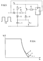
- FIG. 1 shows a circuit arrangement shown in the block diagram of a converter with a control module.
- This converter with control module essentially consists of the circuit module of a converter C, a pulse width modulator PWM, an error amplifier F and a clock generator whose frequency (VCO) can be changed and a detector circuit D which detects, for example, a short-circuit or overload case and accordingly over its output signal regulates the frequency of the clock generator (VCO).
- VCO clock generator
- the output signal of the monoflop MF is on the one hand at the connection terminals of the ratio generator V and on the other hand the control signal of the electronic switch is at a second input.
- the ratio generator is used to form the ratio between the duty cycle of the control signal t on to the duty cycle t onmin * of the output signal of the monoflop MF. This "ratio formation" is achieved by synchronous averaging of the signals listed above.
- the pulse width modulator PWM is controlled by a current flowing on the primary side in the measuring resistor of the main circuit and an output voltage applied to the converter on the secondary side influenced.
- the output signal of the pulse width modulator PWM determines the duty cycle of the electronic switch of the converter C.
- This output signal which is present at the output terminals PG of the pulse width modulator PWM and whose pulse width is influenced by the measured values determined on the primary or secondary side at the transformer of the converter, is at the input of the detector circuit D.
- the control signal t on for the electronic switch triggers the monoflop MF arranged in the detector circuit D.
- This monoflop MF generates a defined time window for the synchronous averaging.
- the pulse length of the output signal of the monoflop t onmin * defines the switch-on time from which the converter works frequency-modulated.
- the converter In this operating phase, the converter is operated with a constant switch-on time t on , but with a variable frequency.
- the mode of operation of the detector circuit D is shown in FIG. 2 on the basis of pulse diagrams and explained on the basis of the circuit structure shown in FIG.
- the operating point of the converter is recognized by the detector circuit D, from which the output current begins to rise in an uncontrolled manner.
- the increase in the output current occurs at the minimum possible switch-on time t onmin , since the duty cycle is due to the delay times cannot be reduced further.
- the detector circuit D prevents the converter from reaching this shortest possible on-time t onmin .
- the current switch-on time t on is measured.
- the effective pulse duty factor t on / T neu is thus reduced without the switch-on time ton having to be shortened.
- the constant switch-on time t onmin * of the MF is preferably slightly above t onmin .
- the ratio t on / t onmin * of the current duty cycle t on to the defined minimum duty cycle t onmin * is converted into a voltage proportional to this duty cycle.
- FIG. 2 shows pulse diagrams 2A to 2F to explain the circuit arrangement shown in FIG.
- Line 2A shows the control signal t on , which controls the electronic switch of the converter in accordance with pulse width modulation by the pulse width modulator PWM.
- Line 2B shows the output signal of the monostable multivibrator MF. Due to an increasing overload or relief at the output of the converter, the switch-on time t on or the pulse width of the control signal is continuously reduced. From a certain point in time, here t on ⁇ t onmin * , the frequency of the clock generator is reduced.
- FIG. 2C shows the charging time or, in line 2D, the discharging time of a capacitor C1 arranged in the comparator V of the detector circuit D.
- the capacitor C1 is discharged, as indicated in line 2D, when the pulse width of the control signal falls below the pulse width of the output signal output by the monoflop MF.
- the logic of the detector circuit D is also reproduced in a certain way in line 2E: If the pulse width ton of the control signal is greater than the pulse width t onmin * of the monoflop MF, the capacitor C1 is charged during the "low" signal at the output of the monoflop MF held. The pulse width of the control signal smaller than the pulse width of the monoflop MF, the charging time of the capacitor is shortened accordingly.
- the capacitor C1 discharges during the time difference t onmin * - t on (see line 2D).
- the control signal present at capacitor C1 is shown in line 2F.
- the maximum possible voltage across R1 is present across capacitor C1. If the pulse duration of the monoflop MF falls below the pulse duration of the control signal, the capacitor C1 is discharged accordingly via R2.
- the voltage U C1 controlling the clock generator (VCO) corresponds in each case to the ratio of the pulse widths t onmin * to t on .
- FIG. 3 shows a circuitry implementation of the detector circuit D. It is composed of the monoflop MF and the synchronous mean value image V.
- the drive signal t on which is emitted by the pulse width modulator PWM, is present.
- the control signal U C1 for the clock generator (VCO) is tapped at the capacitor C1.
- the monostable multivibrator MF is triggered at the same time. This emits a pulse of a certain pulse width at output Q. For example, transistor T1 is blocked during the high potential of the pulse.
- the charging circuit for the capacitor C1 is charged by the operating potential source designated U h via the resistor R1 and the diode D2.
- FIG. 4 shows the curve profiles marked a, b.
- the curve marked a occurs when, for example in the case of a low-impedance short circuit, the pulse duration of the control signal has to go to zero, but this is not possible due to the signal delays caused by technology and the output current continues to increase.
- the mode of operation of the detector circuit D and the output characteristic curve of a converter to be achieved thereby are shown in the curve profile marked b.
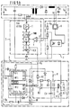
- FIG. 5a shows a circuit arrangement in connection with the control module TDA4916G from Siemens AG.
- a control circuit S (TDA 4916 G) is used to control the electronic switch of the converter C.
- the electronic switch is connected with its control electrode to the control output 4 of the control circuit S.
- the controller R is connected to the outputs b1, b2 of the converter.
- An opto-coupler, the photodiode of which is connected to the regulator R, is arranged between the regulator R and the control circuit S.
- the phototransistor of the opto-coupler is at the reference potential on the emitter side.
- the control circuit S also contains the clock generator G (expanded to a voltage-controlled oscillator (VCO) by the circuitry), to the output of which an arrangement consisting of a logic arrangement and the pulse width modulator is connected. This arrangement is controlled by a comparator K. Between the output of the pulse width modulator and the gate electrode of the electronic switch is a driver T, which outputs control pulses with a variable pulse duty factor at its output to the gate electrode of the electronic switch. Furthermore, a synchronization module SYN is present in the control circuit S, which influences the clock generator.
- VCO voltage-controlled oscillator
- the monoflop MF provided for the circuit arrangement D for generating the time t onmin * is realized with the components R3, R4, R5, T2 and C2.
- a "high" signal at the output 14 of the control circuit S drives the transistor T2 via the level adjustment R3 and R4, as a result of which C2 can discharge.
- the signal at the output 14 of the control circuit S is on "Low" potential leads, the transistor T2 is blocked and C2 can charge via R5.
- the voltage potential at the capacitor C2 is compared with a reference voltage source Uref via a differential amplifier consisting of R8, R9, R10, T3 and T4.
- the differential amplifier can also be designed as an operational amplifier or comparator.
- the reference voltage source U Ref can also be arranged in the control module S. Only as long as the potential at the capacitor C2 is less than the reference voltage U Ref can the synchronous mean value image V, consisting of R1, R2, D1, D2, D3, T1 and C1, work as described under FIG. 3.
- the resistor R7 effects a positive feedback of the differential amplifier and thus enables shorter switching times.
- the switching behavior is further improved by C3 or the anti-saturation diode D4. If the voltage potential at C2 reaches the level of the reference voltage, the transistor T3 of the differential amplifier switches through and the transistor T1 is also turned on, as a result of which the capacitor C1 of the synchronous mean value generator V can no longer discharge.
- the circuit thus maps the ratio V ⁇ t on / t onmin * at capacitor C1.
- the gain factor V can be adjusted by dimensioning R1 and R2.
- the control signal obtained at C1 controls the actuator T5, which determines the operating frequency of the control module S. Case 1: t on > t onmin *
- FIG. 5b shows a further circuit design of the block diagram shown in FIG. 1.
- the function of the circuit arrangement shown in FIG. 5b corresponds to the function of the circuit arrangement shown in FIG. 5a, the discrete monostable multivibrator MF being replaced by an integrated circuit (IC14528), here two independent monostable multivibrators MF1, MF2.
- IC14528 integrated circuit
- MF1 monostable multivibrators
- a monostable flip-flop is sufficient for the function of the circuit.
- the integrated circuit (IC 14528) causes a switching delay of the drive signal for the synchronous mean value V.
- the second monostable multivibrator MF2 is used in this integrated circuit for pulse processing.
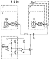
- FIG. 6a shows a circuit arrangement in which several converters C1,..., Cn work synchronously.
- one of the inverters here Cn
- it When one of the inverters (here Cn) changes from constant frequency to variable frequency operation, it must be disconnected from the common synchronization.
- FIGS. 6a, 6b two possibilities are shown in FIGS. 6a, 6b, for example.
- the synchronization is interrupted when the current limitation is used.
- the synchronization clock is on Input 13 of the control module capacitively coupled. If the output of the "slave" is so heavily loaded that the current limitation of the converter intervenes, the operational amplifier OP switches its output to high potential and the transistor T is driven.
- the synchronization pulses arriving from the master are thus decoupled from the "slave", as a result of which it operates unsynchronized and, if the output current should rise further, can reduce its operating frequency in accordance with a frequency-variable converter.
- the converter works unsynchronized after the current limit is used.
- the operational amplifier OP checks the control signal on the capacitor C1 and compares it with a reference voltage U ref .
- the resistors R1, R2 are responsible for level adjustment or, in conjunction with the capacitor C2, for further smoothing of the signal.
- the resistor R3 causes positive feedback to ensure hysteresis between the synchronous and non-synchronous operation of the converter. Since the control signal U C1 on the capacitor C1 only changes when the circuit described above intervenes, the transition from frequency-constant to frequency-variable operation only begins as soon as this is necessary for the "correct" function of the circuit.
Abstract
Description
Pulsweitenmodulierte Umrichter, insbesondere Gleichstromumrichter arbeiten im Normalbetrieb mit konstanter Arbeitsfrequenz. Die Regelung der Ausgangsspannung des Umrichters erfolgt durch eine Änderung des Tastverhältnisses ton/T des Ansteuersignals für den elektronischen Schalter des Umrichters. Um eine konstante Spannung an den Ausgangsklemmen des Umrichters zu erhalten, wird diese beispielsweise mit einem vorgegebenen Spannungssollwert in einem Fehlerverstärker verglichen. Der Fehlerverstärker gibt dabei bei einer Abweichung vom Spannungssollwert die verstärkte Regelabweichung an einen Steuereingang des Pulsweitenmodulators weiter. Dieser regelt entsprechend der Größe der verstärkten Regelabweichung das Tastverhältnis ton/T des am Ausgang des Pulsweitenmodulators anliegenden Ansteuersignals für den elektrischen Schalter.Pulse-width modulated converters, in particular direct current converters, operate in normal operation with a constant operating frequency. The output voltage of the converter is regulated by changing the pulse duty factor t on / T of the control signal for the electronic switch of the converter. In order to obtain a constant voltage at the output terminals of the converter, this is compared, for example, with a specified voltage setpoint in an error amplifier. In the event of a deviation from the voltage setpoint, the error amplifier forwards the amplified control deviation to a control input of the pulse width modulator. This controls the pulse duty factor ton / T of the control signal at the output of the pulse width modulator for the electrical switch in accordance with the magnitude of the amplified control deviation.
Im Überlastfall, das heißt, der an dem Umrichter ausgangsseitig angeschlossene Verbraucher wird niederohmig, sorgt eine Strombegrenzungsschaltung für eine Reduzierung des Taktverhältnisses des elektronischen Schalters des Umrichters. Diese Strombegrenzungsschaltung mißt z.B. über einen Shunt (Meßwiderstand) den im Primärstromkreis des Umrichters fließenden Strom und schaltet, nach Erreichen eines kritischen Stromschwellenwertes, den elektronischen Schalter vorzeitig ab. Die Messung des Primärstromes und das Abschalten des elektronischen Schalters ist jedoch mit einer Verzugszeit beaufschlagt. Die Verzugszeit setzt sich beispielsweise durch die Schaltzeiten innerhalb einer Vergleichseinheit, der Signallaufzeit im Steuer-IC, der Zeit in der das Ausgangssignal für den elektronischen Schalter zurückgesetzt wird und durch die Schaltzeit, die der elektronische Schalter benötigt bis er nach Eintreffen des Abschaltesignals den Primärstromkreis unterbricht, zusammen. Werden diese zum größten Teil schaltungstechnisch sowie technologisch bedingten Signalverzögerungszeiten addiert, ergibt sich die minimal mögliche Einschaltzeit tonmin für den Umrichter. Da die Ausgangsspannung des Umrichters von dem Verhältnis ton /T bestimmt wird, folgt daraus, daß bei niederohmigem Kurzschluß die Einschaltzeit ton des elektronischen Schalters gegen Null gehen muß. Da dies aber aufgrund der Signalverzögerungszeiten nicht möglich ist, beginnt der Ausgangsstrom bei einem niederohmigen Kurzschluß stark anzusteigen. Dieser Kurzschlußstrom, der unter Umständen für den elektronischen Schalter bzw. den oder die Gleichrichter zerstören kann, tritt verstärkt bei Umrichtern mit hoher Ausgangsspannung, bei Umrichtern mit einem hohen Wirkungsgrad und bei hoher Arbeitsfrequenz auf.In the event of an overload, that is to say the consumer connected to the converter on the output side becomes low-resistance, a current limiting circuit ensures a reduction in the clock ratio of the converter's electronic switch. This current limiting circuit measures, for example via a shunt (measuring resistor), the current flowing in the primary circuit of the converter and, after reaching a critical current threshold value, switches off the electronic switch prematurely. However, the measurement of the primary current and the switching off of the electronic switch have a delay time. The delay time is set, for example, by the switching times within a comparison unit, the signal runtime in the control IC, the time in which the output signal for the electronic switch is reset and the switching time that the electronic switch requires until it interrupts the primary circuit after the switch-off signal arrives , together. For the most part When adding signal delay times in terms of circuitry and technology, the minimum possible switch-on time t onmin results for the converter. Since the output voltage of the converter is determined by the ratio t on / T, it follows that in the case of a low-resistance short circuit, the switch-on time t on of the electronic switch must go to zero. However, since this is not possible due to the signal delay times, the output current begins to rise sharply in the event of a low-resistance short circuit. This short-circuit current, which can possibly destroy the electronic switch or the rectifier or rectifiers, occurs increasingly in converters with a high output voltage, in converters with a high efficiency and at a high operating frequency.
Wird der Umrichter bei Schwachlast betrieben, so muß ebenfalls das Tastverhältnis ton/T stark reduziert werden, da die übertragene Leistung des Systems größer als die dem Umrichter am Schaltungsausgang abverlangte Leistung ist. Bei vorgegebener Periodendauer T wird im Leerlauf dann eine kürzere Einschaltzeit ton des elektronischen Schalters benötigt, die kürzer ist als die minimal mögliche Einschaltzeit tonmin des elektronischen Schalters des Umrichters. Wenn die Ausgangsspannung des Umrichters über einen vorgegebenen Spannungsollwert liegt, hindert zudem der Fehlerverstärker den elektronischen Schalter an einem erneuten Durchschalten. Ein Einschalten des elektronischen Schalters erfolgt erst dann, wenn die Ausgangsspannung wieder unter den Spannungssollwert abgesunken ist und durch den Fehlerverstärker wieder freigegeben wird. Eine solche Schaltungsausgestaltung eines Umrichters ist beispielsweise aus der deutschen Patentschrift DE 28 38 009 bekannt.If the converter is operated at low load, the duty cycle t on / T must also be greatly reduced, since the transmitted power of the system is greater than the power demanded of the converter at the circuit output. For a given period T, a shorter switch-on time t on of the electronic switch is then required, which is shorter than the minimum possible switch-on time t onmin of the electronic switch of the converter. If the output voltage of the converter is above a specified voltage setpoint, the error amplifier also prevents the electronic switch from switching through again. The electronic switch is only switched on when the output voltage has dropped below the voltage setpoint again and is enabled again by the error amplifier. Such a circuit configuration of a converter is known for example from the German patent DE 28 38 009.
Die oben genannten Probleme treten bei einem Umrichter mit konstantem ton und variabler Frequenz nicht auf. Nachteil einer solchen Ausgestaltung eines Umrichters ist allerdings, daß über den gesamten Lastbereich zwischen Leerlauf- und Kurzschlußbetrieb die Arbeitsfrequenz des Umrichters entsprechend den Lastverhältnissen an den Ausgangsanschlußklemmen des Umrichters angepaßt wird und es aufgrund der unterschiedlichen Arbeitsfrequenzen nicht möglich ist, mehrere Umrichter miteinander zu synchronisieren.The above-mentioned problems do not occur with a converter with constant t on and variable frequency. The disadvantage of such a configuration of a converter is, however, that the operating frequency of the converter is adapted over the entire load range between idle and short-circuit operation in accordance with the load conditions at the output terminals of the converter and it is not possible to synchronize several converters with one another due to the different working frequencies.
Bei einer Spannungsversorgungseinheit mit mehreren Ausgangsspannungen, werden unter Umständen mehrere Umrichter für die entsprechenden Ausgangsspannungen dimensioniert. Aus schaltungstechnischen Gründen werden die speziell dimensionierten Umrichter untereinander synchronisiert. Die Vorteile liegen in der Verwendung einer einheitlichen Schaltfrequenz. Durch geeignete Phasenwahl der beispielsweise im Gegentakt betriebenen Umrichter, verringert sich die Wechselstrombelastung der Zwischenkreiskondensatoren.In the case of a voltage supply unit with several output voltages, several inverters may be dimensioned for the corresponding output voltages. For reasons of circuitry, the specially dimensioned inverters are synchronized with each other. The advantages lie in the use of a uniform switching frequency. The AC load on the intermediate circuit capacitors is reduced by suitable phase selection of the converters, for example, operated in push-pull mode.
Bei synchronisierten Umrichtern kann ein gemeinsames Endstörfilter verwendet werden. Werden die Umrichter nicht synchronisiert betrieben, so würden sich aufgrund der unvermeidlichen Toleranzen die Arbeitsfrequenzen der einzelnen Umrichter geringfügig unterscheiden. Dieser Unterschied in der Arbeitsfrequenz wirkt sich als Schwebung auf die gemeinsame Spannungsversorgung der Umrichterschaltungen aus. Da die Rückwirkungen auf die Spannungsversorgung bestimmten, festgelegten Grenzwerten unterliegen, müssen störende Frequenzen mit entsprechend dimensionierten Filtern von den Versorgungszuleitungen ferngehalten werden. Da die Schwebungsfrequenz der Differenzfrequenzen der einzelnen Umrichter entspricht, beginnt das mögliche Frequenzspektrum bei 0 Hz, wodurch eine Filterdimension unmöglich ist. Die Umrichter müßten bei unsynchronisierten Betrieb einzeln entstört werden.A common end interference filter can be used for synchronized inverters. If the inverters are not operated synchronized, the working frequencies of the individual inverters would differ slightly due to the inevitable tolerances. This difference in the operating frequency affects the common voltage supply of the converter circuits as a beat. Since the repercussions on the voltage supply are subject to certain, defined limit values, disturbing frequencies must be kept away from the supply lines with appropriately dimensioned filters. Since the beat frequency corresponds to the difference frequencies of the individual inverters, the possible frequency spectrum starts at 0 Hz, making a filter dimension impossible. The converters would have to be individually suppressed in unsynchronized operation.
Aufgabe der Erfindung ist es, einen Umrichter derart auszugestalten, daß dieser im Schwachlast- bzw. Überlastfall frequenzvariabel und im normalen Betriebsfall mit einer konstanten Arbeitsfrequenz mit Pulsweitenmodulation betrieben werden kann.The object of the invention is to design a converter in such a way that it can be operated at variable frequencies in the low-load or overload case and in normal operation at a constant operating frequency with pulse width modulation.
Die Aufgabe wird durch die Merkmale des Patentanspruchs 1 gelöst.The object is achieved by the features of
Die Erfindung weist den Vorteil auf, daß im normalen Betriebsfall der Umrichter mit konstanter Frequenz arbeitet und mit anderen Umrichtern synchronisiert werden kann, während im Schwachlast- bzw. Überlastfall das Tastverhältnis durch eine neue Periodendauer geändert wird und so im Schwachlast- und Kurzschlußfall die Arbeitsfrequenz reduziert wird und ein weiteres Ansteigen der Ausgangsspannung bzw. des Kurzschlußstromes verhindert wird.The invention has the advantage that in normal operation the converter operates at a constant frequency and can be synchronized with other converters, while in the case of low load or overload the duty cycle is changed by a new period and thus reduces the operating frequency in the case of low load and short circuit and a further increase in the output voltage or the short-circuit current is prevented.
In der erfindungsgemäßen Schaltungsanordnung werden die Vorteile eines frequenzvariablen Umrichters im Schwachlast- und Überlastfall mit den Vorteilen eines frequenzkonstanten mit Pulsbreitenmodulation betriebenen Umrichters kombiniert. Im normalen Betriebsfall arbeitet der Umrichter wie ein Umrichter mit konstanter Frequenz und kann mit anderen Umrichtern synchronisiert werden. Im Überlast- bzw. Schwachlastfall behält der Umrichter seine minimale Einschaltdauer tonmin* bei, ändert aber entsprechend den Strom- oder Spannungsverhältnissen die Arbeitsfrequenz. Im Fehlerfall, der beispielsweise bei Lastabwurf oder Kurzschluß eintritt, wird dem Taktgeber (VCO) ein Stellsignal zugeführt wodurch sich die Taktfrequenz solange ändert, bis sich wieder ein stationärer Betriebszustand einstellt. Ein unzulässig hoher Ausgangsstrom im Überlastfall sowie eine Paketansteuerung im Schwachlastfall wird hierdurch wirksam unterbunden. Bei synchron arbeitenden Umrichtern wird der Umrichter bei dem der Fehlerfall auftrat, solange von den anderen abgekoppelt, bis sich wieder ein normaler Betriebszustand einstellt.In the circuit arrangement according to the invention, the advantages of a frequency-variable converter in the case of light loads and overloads are combined with the advantages of a frequency-constant converter operated with pulse-width modulation. In normal operation, the converter works like a converter with a constant frequency and can be synchronized with other converters. In the event of an overload or low load, the converter maintains its minimum duty cycle t onmin * , but changes the operating frequency according to the current or voltage conditions. In the event of a fault, which occurs, for example, in the event of a load shedding or short circuit, an actuating signal is fed to the clock generator (VCO), as a result of which the clock frequency changes until a steady operating state is restored. This effectively prevents an impermissibly high output current in the event of an overload and package control in the event of a low load. In the case of inverters operating synchronously, the inverter in which the fault occurred occurred is decoupled from the others until a normal operating state is restored.
Weitere Besonderheiten der Erfindung werden aus der nachfolgenden näheren Erläuterung eines Ausführungsbeispiels anhand von Zeichnungen ersichtlich.Further special features of the invention will become apparent from the following detailed explanation of an exemplary embodiment with reference to drawings.
Es zeigen:
- Fig. 1
- ein Blockschaltbild,
- Fig. 2A-2F
- Impulsdiagramme,
- Fig. 3
- eine schaltungstechnische Realisierung,
- Fig. 4
- Ausgangskennlinien des Umrichters,
- Fig. 5a/b
- weitere Schaltungsbeispiele, und
- Fig. 6a/b
- Synchronisationsschaltungen.
- Fig. 1
- a block diagram,
- 2A-2F
- Pulse diagrams,
- Fig. 3
- a circuit implementation,
- Fig. 4
- Output characteristics of the converter,
- Fig. 5a / b
- further circuit examples, and
- 6a / b
- Synchronization circuits.
Figur 1 zeigt eine im Blockschaltbild dargestellte Schaltungsanordnung einen Umrichter mit Ansteuermodul. Dieser Umrichter mit Ansteuermodul besteht im wesentlichen aus dem Schaltungsmodul eines Konverters C, eines Pulsweitenmodulators PWM, eines Fehlerverstärkers F sowie eines Taktgebers, dessen Frequenz (VCO) veränderbar ist und aus einer Detektorschaltung D, die z.B. einen Kurzschluß- bzw. Überlastfall erkennt und entsprechend über ihr Ausgangssignal die Frequenz des Taktgebers (VCO) regelt. In der Detektorschaltung D ist im wesentlichen ein auf eine bestimmbare Einschaltzeit tonmin* dimensioniertes monostabiles Kippglied MF, sowie ein Verhältnisbildner V vorgesehen. An den Anschlußklemmen des Verhältnisbildners V liegt einerseits an einem ersten Eingang das Ausgangssignal des Monoflops MF sowie andererseits an einem zweiten Eingang das Ansteuersignal des elektronischen Schalters. Der Verhältnisbildner dient dazu, das Verhältnis zwischen der Einschaltdauer des Ansteuersignals ton zur Einschaltdauer tonmin* des Ausgangssignals des Monoflops MF zu bilden. Diese "Verhältnisbildung", wird durch eine synchrone Mittelwertbildung der oben aufgeführten Signale erreicht.FIG. 1 shows a circuit arrangement shown in the block diagram of a converter with a control module. This converter with control module essentially consists of the circuit module of a converter C, a pulse width modulator PWM, an error amplifier F and a clock generator whose frequency (VCO) can be changed and a detector circuit D which detects, for example, a short-circuit or overload case and accordingly over its output signal regulates the frequency of the clock generator (VCO). In the detector circuit D, a monostable multivibrator MF dimensioned to a determinable switch-on time t onmin * and a ratio generator V are essentially provided. The output signal of the monoflop MF is on the one hand at the connection terminals of the ratio generator V and on the other hand the control signal of the electronic switch is at a second input. The ratio generator is used to form the ratio between the duty cycle of the control signal t on to the duty cycle t onmin * of the output signal of the monoflop MF. This "ratio formation" is achieved by synchronous averaging of the signals listed above.
Der Pulsweitenmodulator PWM wird über einen primärseitig fließenden Strom im Meßwiderstand des Hauptstromkreises und einer sekundärseitig am Umrichter anliegenden Ausgangsspannung beeinflußt. Das Ausgangssignal des Pulsweitenmodulators PWM bestimmt den Tastgrad des elektronischen Schalters des Umrichters C. Dieses an den Ausgangsklemmen PG des Pulsweitenmodulators PWM anliegende Ausgangssignal, dessen Impulsbreite beeinflußt von den primär- bzw. sekundärseitig am Übertrager des Umrichters ermittelten Meßwerten, liegt am Eingang der Detektorschaltung D.The pulse width modulator PWM is controlled by a current flowing on the primary side in the measuring resistor of the main circuit and an output voltage applied to the converter on the secondary side influenced. The output signal of the pulse width modulator PWM determines the duty cycle of the electronic switch of the converter C. This output signal, which is present at the output terminals PG of the pulse width modulator PWM and whose pulse width is influenced by the measured values determined on the primary or secondary side at the transformer of the converter, is at the input of the detector circuit D.
Mit dem Ansteuersignal ton für den elektronischen Schalter wird das in der Detektorschaltung D angeordnete Monoflop MF getriggert. Dieses Monoflop MF erzeugt ein definiertes zeitliches Fenster für die synchrone Mittelwertbildung. Die Pulslänge des Ausgangssignals des Monoflops tonmin* legt die Einschaltzeit fest, ab der der Umrichter frequenzmoduliert arbeitet.The control signal t on for the electronic switch triggers the monoflop MF arranged in the detector circuit D. This monoflop MF generates a defined time window for the synchronous averaging. The pulse length of the output signal of the monoflop t onmin * defines the switch-on time from which the converter works frequency-modulated.
Während der Zeit tonmin* in der am Ausgang Q des Monoflops MF ein Impulssignal anliegt, wird ein analoges Stellsignal Uc1 unabhängig von der sich einstellenden Frequenz gewonnen. Dieses Stellsignal Uc1 beeinflußt die Ausgangsfrequenz des Taktgebers (VCO). Bei dem gezeigten Blockschaltbild in Fig. 1 ergibt sich beispielsweise im Überlast- bzw. Schwachlastfall nachfolgende Regelschleife: ton ≦ tonmin*; Detektor verringert Oszillatorfrequenz; effektives Tastverhältnis ton / Tneu wird kleiner.During the time t onmin * in which a pulse signal is present at the output Q of the monoflop MF, an analog actuating signal U c1 is obtained regardless of the frequency which arises. This control signal U c1 influences the output frequency of the clock generator (VCO). In the block diagram shown in FIG. 1, the following control loop results, for example, in the event of an overload or low load: t on ≦ t onmin * ; Detector reduces oscillator frequency; effective duty cycle t on / T new becomes smaller.
Der Umrichter wird in dieser Betriebsphase mit konstanter Einschaltzeit ton, aber mit variabler Frequenz betrieben. Die Arbeitsweise der Detektorschaltung D wird in Figur 2 anhand von Impulsdiagrammen wiedergegeben und anhand des in Figur 3 dargestellten Schaltungsaufbaus erläutert. Im Überlastfall wird durch die Detektorschaltung D der Arbeitspunkt des Umrichters erkannt, ab dem der Ausgangsstrom unkontrolliert anzusteigen beginnt.In this operating phase, the converter is operated with a constant switch-on time t on , but with a variable frequency. The mode of operation of the detector circuit D is shown in FIG. 2 on the basis of pulse diagrams and explained on the basis of the circuit structure shown in FIG. In the event of an overload, the operating point of the converter is recognized by the detector circuit D, from which the output current begins to rise in an uncontrolled manner.
Das Ansteigen des Ausgangsstromes tritt bei der minimal möglichen Einschaltzeit tonmin auf, da das Tastverhältnis aufgrund der Verzugszeiten nicht weiter verkürzt werden kann. Die Detektorschaltung D verhindert, daß der Umrichter diese kürzest mögliche Einschaltdauer tonmin erreicht. Die aktuelle Einschaltzeit ton wird gemessen. Bei Annäherung der Einschaltzeit ton an die minimale mögliche Einschaltzeit tonmin, wird die Einschaltzeit des elektronischen Schalters konstant gehalten und die Arbeitsfrequenz des Taktgebers (VCO) auf fneu = 1/Tneu erniedrigt. Das effektive Tastverhältnis ton/Tneu verringert sich somit, ohne daß sich die Einschaltzeit ton zu verkürzen müßte. Die konstante Einschaltzeit tonmin* des MF liegt vorzugsweise geringfügig über tonmin. Das Verhältnis ton/tonmin* der aktuellen Einschaltdauer ton zur festgelegten minimalen Einschaltdauer tonmin* wird in eine, diesem Tastverhältnis proportionale Spannung umgesetzt.The increase in the output current occurs at the minimum possible switch-on time t onmin , since the duty cycle is due to the delay times cannot be reduced further. The detector circuit D prevents the converter from reaching this shortest possible on-time t onmin . The current switch-on time t on is measured. When the switch-on time ton approaches the minimum possible switch-on time t onmin , the switch-on time of the electronic switch is kept constant and the operating frequency of the clock generator (VCO) is reduced to f new = 1 / T new . The effective pulse duty factor t on / T neu is thus reduced without the switch-on time ton having to be shortened. The constant switch-on time t onmin * of the MF is preferably slightly above t onmin . The ratio t on / t onmin * of the current duty cycle t on to the defined minimum duty cycle t onmin * is converted into a voltage proportional to this duty cycle.
In Figur 2 sind zur Erläuterung der in der Figur 1 wiedergegebenen Schaltungsanordnung Impulsdiagramme 2A bis 2F wiedergegeben. Unter Zeile 2A ist das Ansteuersignal ton gezeigt, das entsprechend pulsweitenmoduliert durch den Pulsweitenmodulator PWM den elektronischen Schalter des Umrichters steuert. In Zeile 2B ist das Ausgangssignal des monostabilen Kippgliedes MF wiedergegeben. Aufgrund einer zunehmenden Überlast oder Entlastung am Ausgang des Umrichters wird die Einschaltzeit ton bzw. die Impulsbreite des Ansteuersignals ständig verringert. Ab einem bestimmten Zeitpunkt, hier ton ≦ tonmin* wird die Frequenz des Taktgebers verringert. In Figur 2C ist die Ladezeit bzw. in Zeile 2D die Entladezeit eines im Vergleicher V der Detektorschaltung D angeordneten Kondensators C1 wiedergegeben. Der Kondensator C1 wird wie in Zeile 2D angedeutet entladen, wenn die Impulsbreite des Ansteuersignals die Impulsbreite des vom Monoflop MF abgegebenen Ausgangssignals unterschreitet. In Zeile 2E ist in gewisser Weise auch die Logik der Detektorschaltung D wiedergegeben: Ist die Impulsbreite ton des Ansteuersignals größer als die Impulsbreite tonmin* des Monoflops MF so wird während dem "Low" -Signal am Ausgang des Monoflops MF die Ladung des Kondensators C1 gehalten. Wird die Impulsbreite des Ansteuersignals kleiner als die Impulsbreite des Monoflops MF, so verkürzt sich entsprechend die Ladezeit des Kondensators. Während der Zeitdifferenz tonmin* - ton entlädt sich der Kondensator C1(siehe Zeile 2D). Dargestellt ist das am Kondensator C1 anliegende Stellsignal in Zeile 2F. Während der Ladephase liegt am Kondensator C1 die maximal mögliche Spannung über R1 an. Wenn die Impulsdauer des Monoflops MF die Impulsdauer des Ansteuersignals unterschreitet wird der Kondensator C1 entsprechend über R2 entladen. Die den Taktgeber (VCO) steuernde Spannung UC1 (siehe Figur 3) entspricht jeweils dem Verhältnis der Impulsbreiten tonmin* zu ton.FIG. 2 shows pulse diagrams 2A to 2F to explain the circuit arrangement shown in FIG. Line 2A shows the control signal t on , which controls the electronic switch of the converter in accordance with pulse width modulation by the pulse width modulator PWM. Line 2B shows the output signal of the monostable multivibrator MF. Due to an increasing overload or relief at the output of the converter, the switch-on time t on or the pulse width of the control signal is continuously reduced. From a certain point in time, here t on ≦ t onmin * , the frequency of the clock generator is reduced. FIG. 2C shows the charging time or, in line 2D, the discharging time of a capacitor C1 arranged in the comparator V of the detector circuit D. The capacitor C1 is discharged, as indicated in line 2D, when the pulse width of the control signal falls below the pulse width of the output signal output by the monoflop MF. The logic of the detector circuit D is also reproduced in a certain way in line 2E: If the pulse width ton of the control signal is greater than the pulse width t onmin * of the monoflop MF, the capacitor C1 is charged during the "low" signal at the output of the monoflop MF held. The pulse width of the control signal smaller than the pulse width of the monoflop MF, the charging time of the capacitor is shortened accordingly. The capacitor C1 discharges during the time difference t onmin * - t on (see line 2D). The control signal present at capacitor C1 is shown in line 2F. During the charging phase, the maximum possible voltage across R1 is present across capacitor C1. If the pulse duration of the monoflop MF falls below the pulse duration of the control signal, the capacitor C1 is discharged accordingly via R2. The voltage U C1 controlling the clock generator (VCO) (see FIG. 3) corresponds in each case to the ratio of the pulse widths t onmin * to t on .
Figur 3 zeigt eine schaltungstechnische Realisierung der Detektorschaltung D. Sie setzt sich aus dem Monoflop MF und dem synchronen Mittelwertbilder V zusammen. Am Eingang des Detektors D der mit E bezeichneten Anschlußklemmen liegt das vom Pulweitenmodulator PWM abgegebene Ansteuersignal ton an. Das Stellsignal UC1 für den Taktgeber (VCO) wird am Kondensator C1 abgegriffen. Mit steigender Flanke des am Eingang E anliegenden Ansteuersignals wird gleichzeitig die monostabile Kippstufe MF getriggert. Diese gibt am Ausgang Q einen Impuls bestimmter Impulsbreite ab. Während dem High-Potential des Impulses wird beispielsweise der Transistor T1 gesperrt. Der Ladestromkreis für den Kondensator C1 wird von der mit Uh bezeichneten Betriebspotentialquelle über den Widerstand R1 und die Diode D2 geladen. Unterschreitet die Impulsbreite des Ansteuersignals die Impulsbreite des vom Monoflop MF abgegebenen Impulses, so wird der Kondensator C1 entladen. Diese Entladung erfolgt über die Diode D1, über den Widerstand R2 und der Diode D3. Liegt am Ausgang des Monoflops Low-Potential an, wird der Transistor T1 durchgeschaltet. Im durchgeschalteten Zustand des Transistors T1 liegt an der Diode D3 Sperrspannung an und der Kondensator C1 kann sich nicht mehr entladen. Das Entladen des Kondensators C1 findet nur während der Dauer des positiven Ausgangsimpulses des Monoflops MF nach Beendigung des positiven Zustandes des Ansteuersignals statt. Zu allen anderen Zeiten wird die gemittelte Kondensatorladung UC1 gehalten. Somit ergibt sich die Spannung am Kondensator C1 zu Uc1 = v x ton/tonmin*. Die proportionale Verstärkung v und somit die Steilheit der Steuerkennlinie ist von den Lade- bzw. Entladewiderständen R1 und R2 abhängig.FIG. 3 shows a circuitry implementation of the detector circuit D. It is composed of the monoflop MF and the synchronous mean value image V. At the input of the detector D of the terminals labeled E, the drive signal t on, which is emitted by the pulse width modulator PWM, is present. The control signal U C1 for the clock generator (VCO) is tapped at the capacitor C1. With a rising edge of the control signal present at input E, the monostable multivibrator MF is triggered at the same time. This emits a pulse of a certain pulse width at output Q. For example, transistor T1 is blocked during the high potential of the pulse. The charging circuit for the capacitor C1 is charged by the operating potential source designated U h via the resistor R1 and the diode D2. If the pulse width of the control signal falls below the pulse width of the pulse emitted by the monoflop MF, the capacitor C1 is discharged. This discharge takes place via the diode D1, the resistor R2 and the diode D3. If low potential is present at the output of the monoflop, the transistor T1 is turned on. When transistor T1 is switched on, reverse voltage is applied to diode D3 and capacitor C1 can no longer discharge. The capacitor C1 is discharged only during the duration of the positive output pulse of the monoflop MF after the positive state of the control signal has ended. At all other times the averaged capacitor charge U C1 held. The voltage across capacitor C1 thus results in U c1 = vxt on / t onmin * . The proportional gain v and thus the steepness of the control characteristic depends on the charging and discharging resistors R1 and R2.
In der Figur 4 sind die mit a, b gekennzeichneten Kurvenverläufe dargestellt. Der mit a bezeichnete Kurvenverlauf tritt dann ein, wenn wie beispielsweise bei einem niederohmigen Kurzschluß die Impulsdauer des Ansteuersignals gegen Null gehen muß, aber aufgrund der technologisch bedingten Signallaufzeiten dies nicht möglich ist und der Ausgangsstrom weiter zunimmt. Die Wirkungsweise der Detektorschaltung D und die damit zu erzielende Ausgangskennlinie eines Umrichters zeigt der mit b gekennzeichnete Kurvenverlauf.FIG. 4 shows the curve profiles marked a, b. The curve marked a occurs when, for example in the case of a low-impedance short circuit, the pulse duration of the control signal has to go to zero, but this is not possible due to the signal delays caused by technology and the output current continues to increase. The mode of operation of the detector circuit D and the output characteristic curve of a converter to be achieved thereby are shown in the curve profile marked b.
Figur 5a zeigt eine Schaltungsanordnung in Verbindung mit dem Steuerbaustein TDA4916G der Firma Siemens AG. Zur Steuerung des elektronischen Schalters des Umrichters C dient eine Steuerschaltung S (TDA 4916 G). Der elektronische Schalter ist mit seiner Steuerelektrode an dem Steuerausgang 4 der Steuerschaltung S angeschlossen. An den Ausgängen b1, b2 des Umrichters ist der Regler R angeschlossen. Zwischen dem Regler R und der Steuerschaltung S ist ein Opto-Koppler angeordnet, dessen Photodiode an den Regler R angeschlossen ist. Der Phototransistor des Opto-Kopplers liegt emitterseitig am Bezugspotential. Die Steuerschaltung S enthält ferner den Taktgeber G (durch die Beschaltung zu einem spannungsgesteuerten Oszillator (VCO) erweitert), an dessen Ausgang eine aus einer Verknüpfungsanordnung und dem Pulsweitenmodulator bestehende Anordnung angeschlossen ist. Diese Anordnung wird durch einen Komparator K gesteuert. Zwischen dem Ausgang des Pulsweitenmodulators und der Gate-Elektrode des elektronischen Schalters liegt ein Treiber T, der an seinem Ausgang Ansteuerimpulse mit veränderbarem Tastverhältnis an die Gate-Elektrode des elektronischen Schalters abgibt. Desweiteren ist ein Synchronisationsmodul SYN in der Steuerschaltung S vorhanden, das Einfluß auf den Taktgenerator nimmt.Figure 5a shows a circuit arrangement in connection with the control module TDA4916G from Siemens AG. A control circuit S (TDA 4916 G) is used to control the electronic switch of the converter C. The electronic switch is connected with its control electrode to the control output 4 of the control circuit S. The controller R is connected to the outputs b1, b2 of the converter. An opto-coupler, the photodiode of which is connected to the regulator R, is arranged between the regulator R and the control circuit S. The phototransistor of the opto-coupler is at the reference potential on the emitter side. The control circuit S also contains the clock generator G (expanded to a voltage-controlled oscillator (VCO) by the circuitry), to the output of which an arrangement consisting of a logic arrangement and the pulse width modulator is connected. This arrangement is controlled by a comparator K. Between the output of the pulse width modulator and the gate electrode of the electronic switch is a driver T, which outputs control pulses with a variable pulse duty factor at its output to the gate electrode of the electronic switch. Furthermore, a synchronization module SYN is present in the control circuit S, which influences the clock generator.
Das für die Schaltungsanordnung D vorgesehene Monoflop MF zur Erzeugung der Zeit tonmin* ist mit den Bauelementen R3, R4, R5, T2 und C2 realisiert. Ein "High"-Signal am Ausgang 14 der Steuerschaltung S steuert über die Pegelanpassung R3 und R4 den Transistor T2 an, wodurch sich C2 entladen kann. Das Potential an dem Kondensator C2 beträgt nach der Entladung etwa 0 Volt ( = Uce des gleichgesteuerten Transistors T2) und stellt somit einen definierten Startwert für die anschließende Ladung während der Zeit tonmin* dar. Sobald das Signal am Ausgang 14 der Steuerschaltung S ein "Low"-Potential führt, wird der Transistor T2 gesperrt und C2 kann sich über R5 aufladen. Das Spannungspotential am Kondensator C2 wird über einen Differenzverstärker, bestehend aus R8, R9, R10, T3 und T4 mit einer Referenzspannungsquelle Uref verglichen. Der Differenzverstärker kann auch als Operationsverstärker- bzw. Komparator ausgeführt werden. Die Referenzspannungsquelle URef kann ebenfalls im Steuerbaustein S angeordnet sein. Nur solange das Potential am Kondensator C2 kleiner als die Referenzspannung URef ist, kann der synchrone Mittelwertbilder V, bestehend aus R1, R2, D1, D2, D3, T1 und C1 wie unter Fig. 3 beschrieben, arbeiten.The monoflop MF provided for the circuit arrangement D for generating the time t onmin * is realized with the components R3, R4, R5, T2 and C2. A "high" signal at the
Der Widerstand R7 bewirkt eine Mitkopplung des Differenzverstärkers und ermöglicht somit kürzere Schaltzeiten. Das Schaltverhalten wird durch C3 bzw. der Antisättigungsdiode D4 noch weiter verbessert. Erreicht das Spannungpotential an C2 die Höhe der Referenzspannung, so schaltet der Transistor T3 des Differenzverstärkers durch und der Transistor T1 wird ebenfalls leitend gesteuert, wodurch sich der Kondensator C1 des synchronen Mittelwertbildners V nicht weiter entladen kann. Die Schaltung bildet somit das Verhältnis V·ton/tonmin* am Kondensator C1 ab. Der Verstärkungsfaktor V läßt sich durch die Dimensionierung von R1 und R2 einstellen. Das am C1 gewonnene Stellsignal steuert das Stellglied T5 an, das die Arbeitsfrequenz des Steuerbausteins S bestimmt.![]()
![]()
Spannung an C1 ≈ Spannung des Betriebspotentials Uh - der Transistor T5 ist durchgesteuert, d.h. R11 wird kurzgeschlossen und der Widerstand R12 bestimmt die "normale", feste Arbeitsfrequenz des Konverters C.![]()
![]()
Im Verhältnis V·ton/tonmin* verringert sich die Spannung an dem Kondensator C1, wodurch T5 aktiv wird, d.h. der für die Frequenz verantwortliche Widerstand R12 + (R11 // Rds) erhöht sich, wodurch die Arbeitsfrequenz des Steuerbausteins S verringert wird.In the ratio V · t on / t onmin * , the voltage across the capacitor C1 decreases, as a result of which T5 becomes active, ie the resistor R12 + (R11 // R ds ) responsible for the frequency increases, as a result of which the operating frequency of the control module S is reduced becomes.
Figur 5b zeigt eine weitere schaltungstechnische Ausgestaltung des in Figur 1 dargestellten Blockschaltbildes. Die Funktion der in Figur 5b dargestellten Schaltungsanordnung entspricht der Funktion der in 5a dargestellten Schaltungsanordnung, wobei das diskret aufgebaute monostabile Kippglied MF durch einen integrierten Schaltkreis (IC14528), hier zwei unabhängige monostabile Kippstufen MF1, MF2 ersetzt wird. Prinzipiell reicht für die Funktion der Schaltung ein monostabiles Kippglied aus. Der integrierte Schaltkreis (IC 14528) verursacht aber eine Schaltverzögerung des Ansteuerungssignals für den synchronen Mittelwertbilder V. Um diese Schaltungsverzögerung zu kompensieren wird die zweite monostabile Kippstufe MF2 in diesem integrierten Schaltkreis zur Impulsaufbereitung verwendet.FIG. 5b shows a further circuit design of the block diagram shown in FIG. 1. The function of the circuit arrangement shown in FIG. 5b corresponds to the function of the circuit arrangement shown in FIG. 5a, the discrete monostable multivibrator MF being replaced by an integrated circuit (IC14528), here two independent monostable multivibrators MF1, MF2. In principle, a monostable flip-flop is sufficient for the function of the circuit. However, the integrated circuit (IC 14528) causes a switching delay of the drive signal for the synchronous mean value V. To compensate for this switching delay, the second monostable multivibrator MF2 is used in this integrated circuit for pulse processing.
In Figur 6a ist eine Schaltungsanordnung dargestellt, bei der mehrere Konverter C1,...,Cn synchron arbeiten. Beim Übergang eines der Umrichter (hier Cn) vom frequenzkonstanten zum frequenzvariablen Betrieb muß dieser von der gemeinsamen Synchronisation abgekoppelt werden.FIG. 6a shows a circuit arrangement in which several converters C1,..., Cn work synchronously. When one of the inverters (here Cn) changes from constant frequency to variable frequency operation, it must be disconnected from the common synchronization.
In den Figuren 6a, 6b sind hierfür beispielsweise zwei Möglichkeiten aufgezeigt. In der in Figur 6a dargestellten Schaltungsanordnung wird die Synchronisation bei Einsatz der Strombegrenzung unterbrochen. Der Synchronisationstakt ist am Eingang 13 des Steuerbausteins kapazitiv angekoppelt. Wird der Ausgang des "Slaves" so stark belastet, daß die Strombegrenzung des Konverters eingreift, so schaltet der Operationsverstärker OP seinen Ausgang auf High-Potential und der Transistor T wird angesteuert. Die vom Master ankommenden Synchronisationsimpulse werden somit vom "slave" abgekoppelt, wodurch er unsynchronisiert arbeitet und, falls der Ausgangsstrom weiter ansteigen sollte, seine Arbeitsfrequenz entsprechend eines frequenzvariablen Konverters reduzieren kann. Der Konverter arbeitet nach dem Einsatz der Strombegrenzung unsynchronisiert. Will man erreichen, daß die Synchronisation des Umrichters erst beim Eingreifen der erfindungsgemäßen Schaltung verlassen wird, so kann man eine Schaltung, wie in Figur 6b dargestellt verwenden. Der Operationsverstärker OP überprüft das Stellsignal an dem Kondensator C1 und vergleicht es mit einer Referenzspannung Uref. Die Widerstände R1, R2 sind für die Pegelanpassung bzw. auch in Verbindung mit dem Kondensator C2 für eine weitere Glättung des Signals zuständig. Der Widerstand R3 bewirkt eine Mitkopplung um eine Hysterese zwischen dem synchronen und nicht synchronen Betrieb des Konverters zu gewährleisten. Da sich das Stellsignal UC1 am Kondensator C1 erst beim Eingreifen der oben beschriebenen Schaltung ändert, setzt der Übergang vom frequenzkonstanten zu dem frequenzvariablen Betrieb erst ein, sobald dieser für die "korrekte" Funktion der Schaltung notwendig ist.For this purpose, two possibilities are shown in FIGS. 6a, 6b, for example. In the circuit arrangement shown in FIG. 6a, the synchronization is interrupted when the current limitation is used. The synchronization clock is on
Claims (5)
dadurch gekennzeichnet,
daß ein synchroner Mittelwertbilder (V) vorgesehen ist, dessen erstem Eingang ein von der Vorderflanke des Ansteuersignals ausgelöster Vergleichsimpuls konstanter Dauer und dessen zweitem Eingang das vom Pulsweitenmodulator abgegebene Ansteuersignal zugeführt ist, wobei bei gleicher oder geringerer Impulsdauer des Ansteuersignals gegenüber dem Vergleichsimpuls, ein vom synchronen Mittelwertbilder (V) abgegebenes Spannungspotential (Stellsignal) die Ausgangsfrequenz des spannungsgesteuerten Oszillators (VCO) verringert.Converter with a pulse width modulator (PWM), the duration of the pulses of the control signal emitted by the pulse width modulator being changeable by at least one manipulated variable and the clock frequency of the converter being controllable by a voltage controlled oscillator (VCO),
characterized,
that a synchronous mean value image (V) is provided, the first input of which is supplied by a comparison pulse of constant duration triggered by the leading edge of the control signal and the second input of which is supplied the control signal emitted by the pulse width modulator, with the control signal being the same or less than the comparison pulse, one of the synchronous Averaged images (V) of the voltage potential (control signal) reduces the output frequency of the voltage-controlled oscillator (VCO).
dadurch gekennzeichnet,
daß ein monostabiles Kippglied zur Erzeugung des am zweiten Eingang des synchronen Mittelwertbilders (V) anliegenden Impulses vorgesehen ist, wobei die Dauer des Vergleichsimpulses geringfügig über dem minimal möglichen vom Pulsweitenmodulator abgebbaren Impuls des Ansteuersignals liegt.Circuit arrangement according to claim 1,
characterized,
that a monostable flip-flop is provided for generating the pulse present at the second input of the synchronous mean value generator (V), the duration of the comparison pulse being slightly above the minimum possible pulse of the control signal that can be output by the pulse width modulator.
dadurch gekennzeichnet,
daß im einem Kurzschluß- oder Leerlauffall eines pulsweitenmodulierten Umrichters das vom Pulsweitenmodulator (PWM) abgegebene Ansteuersignal einen Impuls gleichbleibender minimaler Dauer aufweist.Circuit arrangement according to claim 1,
characterized,
that in the event of a short-circuit or no-load case of a pulse-width-modulated converter, the control signal emitted by the pulse-width modulator (PWM) has a pulse of constant, minimal duration.
dadurch gekennzeichnet,
daß der Ausgang des monostabilen Kippgliedes (MF) über einen Widerstand (R3) mit der Basis eines Transistors (T1) verbunden ist,
daß ein erster Widerstand (R1) mit dem Emitter des Transistors (T1) sowie das bistabile Kippglied (MF) mit einer ersten Betriebspotentialspannung (Uh) verbunden ist,
daß der Kollektor des Transistors (T1) mit dem einen Anschluß eines zweiten Widerstandes (R2) sowie mit der Kathode einer weiteren Diode (D3) verbunden ist,
daß ein Kondensator (C1) mit der Anode der dritten Diode (D3) sowie mit der Kathode einer zweiten Diode (D2) verbunden ist, daß der weitere Anschluß des ersten Widerstandes (R1) mit der Anode der ersten Diode (D1), sowie mit der Anode der zweiten Diode (D2) und einem weiteren Anschluß des zweiten Widerstandes (R2) verbunden ist,
daß der Schaltungseingang (E) sowohl mit der Kathode der ersten Diode (D1) und dem Triggereingang (T) des bistabilen Kippgliedes (MF) verbunden ist und
daß ein weiterer Anschluß des Kondensators (C1) sowie das monostabile Kippglied (MF) an einer einem Massepotential entsprechendem zweiten Betriebspotentialspannung angeschlossen ist.Circuit arrangement according to one of the preceding claims,
characterized,
that the output of the monostable multivibrator (MF) is connected to the base of a transistor (T1) via a resistor (R3),
that a first resistor (R1) is connected to the emitter of the transistor (T1) and the bistable flip-flop (MF) is connected to a first operating potential voltage (U h ),
that the collector of the transistor (T1) is connected to one connection of a second resistor (R2) and to the cathode of a further diode (D3),
that a capacitor (C1) is connected to the anode of the third diode (D3) and to the cathode of a second diode (D2), that the further connection of the first resistor (R1) to the anode of the first diode (D1), and with the anode of the second diode (D2) and a further connection of the second resistor (R2) is connected,
that the circuit input (E) is connected to both the cathode of the first diode (D1) and the trigger input (T) of the bistable flip-flop (MF) and
that a further connection of the capacitor (C1) and the monostable multivibrator (MF) is connected to a second operating potential voltage corresponding to a ground potential.
dadurch gekennzeichnet,
daß mehrere dieser Schaltungsanordnungen über eine Synchronisationseinheit von einem Master-Taktgenerator gesteuert werden,
daß jedem Mittelwertbilder (V) jeder Schaltungsanordnung eine Vergleichseinheit (VGL) nachgeordnet ist, wobei in der Vergleichseinheit (VGL) das vom Mittelwertbilder (V) abgegebene Spannungspotential des Stellsignals mit einem Referenzspannungspotential verglichen wird und jeweils der Umrichter bei einem Kurzschluß- oder Leerlauffall vom Master-Taktgenerator abgekoppelt wird.Circuit arrangement according to one of the preceding claims,
characterized,
that several of these circuit arrangements are controlled by a master clock generator via a synchronization unit,
that each mean value image (V) of each circuit arrangement is followed by a comparison unit (VGL), in the comparison unit (VGL) the voltage potential of the control signal emitted by the mean value image (V) is compared with a reference voltage potential and the converter in the event of a short circuit or no-load case from the master Clock generator is disconnected.
Applications Claiming Priority (2)
| Application Number | Priority Date | Filing Date | Title |
|---|---|---|---|
| DE19522956 | 1995-06-23 | ||
| DE19522956A DE19522956C2 (en) | 1995-06-23 | 1995-06-23 | Converter |
Publications (3)
| Publication Number | Publication Date |
|---|---|
| EP0750389A2 true EP0750389A2 (en) | 1996-12-27 |
| EP0750389A3 EP0750389A3 (en) | 1997-11-12 |
| EP0750389B1 EP0750389B1 (en) | 1999-04-07 |
Family
ID=7765152
Family Applications (1)
| Application Number | Title | Priority Date | Filing Date |
|---|---|---|---|
| EP96109795A Expired - Lifetime EP0750389B1 (en) | 1995-06-23 | 1996-06-18 | Converter |
Country Status (4)
| Country | Link |
|---|---|
| US (1) | US5757631A (en) |
| EP (1) | EP0750389B1 (en) |
| AT (1) | ATE178742T1 (en) |
| DE (2) | DE19522956C2 (en) |
Cited By (4)
| Publication number | Priority date | Publication date | Assignee | Title |
|---|---|---|---|---|
| GB2311629B (en) * | 1996-03-26 | 2000-03-15 | Raytheon Co | Constant on-time architecture for switching regulators |
| WO2007065739A2 (en) * | 2005-12-06 | 2007-06-14 | Siemens Aktiengesellschaft Östrreich | Method for operating a switched-mode power supply as a flyback converter and switched-mode power supply for carrying out said method |
| DE102006022915A1 (en) * | 2006-05-15 | 2007-11-22 | Conti Temic Microelectronic Gmbh | Motor vehicle function e.g. chassis setting function, controlling signal recording and processing system, has converting-and-coding function with sections, where different width segments are mapped to corresponding digital output value |
| US11923711B2 (en) * | 2021-10-14 | 2024-03-05 | Amogy Inc. | Power management for hybrid power system |
Families Citing this family (9)
| Publication number | Priority date | Publication date | Assignee | Title |
|---|---|---|---|---|
| JPH1084624A (en) * | 1996-09-06 | 1998-03-31 | Funai Electric Co Ltd | Switching power supply |
| JP3472086B2 (en) * | 1997-06-25 | 2003-12-02 | キヤノン株式会社 | Network interface device and network interface method |
| FI973882A (en) * | 1997-10-03 | 1999-04-04 | Nokia Mobile Phones Ltd | Method and arrangement for generating a supply voltage |
| EP1149461A1 (en) * | 1999-10-28 | 2001-10-31 | Koninklijke Philips Electronics N.V. | Device for providing a supply voltage |
| US6718474B1 (en) | 2000-09-21 | 2004-04-06 | Stratus Technologies Bermuda Ltd. | Methods and apparatus for clock management based on environmental conditions |
| EP1213822B1 (en) * | 2000-12-05 | 2006-08-02 | Infineon Technologies AG | Frequency limitation and overload detection in a voltage regulator |
| DE10101995A1 (en) * | 2001-01-18 | 2002-07-25 | Philips Corp Intellectual Pty | Electrical or electronic switching arrangement comprises a detector unit and a comparator unit connected to the detector unit to compare the starting voltage with a reference voltage |
| DE10255587B4 (en) * | 2002-11-28 | 2006-07-13 | Insta Elektro Gmbh | Method for signal-dependent manipulated variable change of actuators |
| DE102010014103A1 (en) | 2010-04-07 | 2011-10-13 | Austriamicrosystems Ag | Frequency selection circuit for a DC-DC converter and method for selecting a frequency thereof |
Citations (2)
| Publication number | Priority date | Publication date | Assignee | Title |
|---|---|---|---|---|
| EP0583038A1 (en) * | 1992-08-10 | 1994-02-16 | Koninklijke Philips Electronics N.V. | Power supply circuit and control circuit for use in a power supply circuit |
| JPH06311736A (en) * | 1993-04-19 | 1994-11-04 | Fujitsu Ltd | Dc/dc converter |
Family Cites Families (11)
| Publication number | Priority date | Publication date | Assignee | Title |
|---|---|---|---|---|
| US3906331A (en) * | 1974-05-30 | 1975-09-16 | Bell Telephone Labor Inc | DC to DC converter with linear pulse processing circuitry |
| DE2838009C2 (en) * | 1978-08-31 | 1980-09-11 | Siemens Ag, 1000 Berlin Und 8000 Muenchen | Current limiting circuit for a direct current converter |
| US4355277A (en) * | 1980-10-01 | 1982-10-19 | Motorola, Inc. | Dual mode DC/DC converter |
| US4446440A (en) * | 1982-01-26 | 1984-05-01 | Hewlett-Packard Company | Dual mode amplifier |
| US4628426A (en) * | 1985-10-31 | 1986-12-09 | General Electric Company | Dual output DC-DC converter with independently controllable output voltages |
| US4772995A (en) * | 1987-01-08 | 1988-09-20 | Veeco Instruments Inc. | Switching supply with pulse width and rate modulation |
| JPH0626480B2 (en) * | 1987-04-15 | 1994-04-06 | 沖電気工業株式会社 | Switching Regulator |
| US4904919A (en) * | 1988-06-21 | 1990-02-27 | Allen-Bradley Company, Inc. | Dual mode control of a PWM motor drive for current limiting |
| US4835669A (en) * | 1988-09-26 | 1989-05-30 | Hughes Aircraft Company | Dual mode flyback power supply |
| US4884183A (en) * | 1989-03-29 | 1989-11-28 | General Electric Company | Dual-mode controlled pulse width modulator |
| ATE124824T1 (en) * | 1991-02-15 | 1995-07-15 | Siemens Ag | CLOCK CONTROLLED INVERTER WITH CURRENT LIMITATION. |
-
1995
- 1995-06-23 DE DE19522956A patent/DE19522956C2/en not_active Expired - Fee Related
-
1996
- 1996-06-18 DE DE59601583T patent/DE59601583D1/en not_active Expired - Fee Related
- 1996-06-18 AT AT96109795T patent/ATE178742T1/en not_active IP Right Cessation
- 1996-06-18 EP EP96109795A patent/EP0750389B1/en not_active Expired - Lifetime
- 1996-06-24 US US08/667,942 patent/US5757631A/en not_active Expired - Fee Related
Patent Citations (2)
| Publication number | Priority date | Publication date | Assignee | Title |
|---|---|---|---|---|
| EP0583038A1 (en) * | 1992-08-10 | 1994-02-16 | Koninklijke Philips Electronics N.V. | Power supply circuit and control circuit for use in a power supply circuit |
| JPH06311736A (en) * | 1993-04-19 | 1994-11-04 | Fujitsu Ltd | Dc/dc converter |
Non-Patent Citations (1)
| Title |
|---|
| PATENT ABSTRACTS OF JAPAN vol. 095, no. 002, 31.März 1995 & JP 06 311736 A (FUJITSU LTD), 4.November 1994, & US 5 627 459 A (ITOYAMA) 6.Mai 1997 * |
Cited By (6)
| Publication number | Priority date | Publication date | Assignee | Title |
|---|---|---|---|---|
| GB2311629B (en) * | 1996-03-26 | 2000-03-15 | Raytheon Co | Constant on-time architecture for switching regulators |
| WO2007065739A2 (en) * | 2005-12-06 | 2007-06-14 | Siemens Aktiengesellschaft Östrreich | Method for operating a switched-mode power supply as a flyback converter and switched-mode power supply for carrying out said method |
| WO2007065739A3 (en) * | 2005-12-06 | 2007-09-13 | Siemens Ag Oestrreich | Method for operating a switched-mode power supply as a flyback converter and switched-mode power supply for carrying out said method |
| DE102006022915A1 (en) * | 2006-05-15 | 2007-11-22 | Conti Temic Microelectronic Gmbh | Motor vehicle function e.g. chassis setting function, controlling signal recording and processing system, has converting-and-coding function with sections, where different width segments are mapped to corresponding digital output value |
| DE102006022915B4 (en) * | 2006-05-15 | 2015-02-26 | Conti Temic Microelectronic Gmbh | Signal acquisition and processing system for a motor vehicle, motor vehicle and method |
| US11923711B2 (en) * | 2021-10-14 | 2024-03-05 | Amogy Inc. | Power management for hybrid power system |
Also Published As
| Publication number | Publication date |
|---|---|
| US5757631A (en) | 1998-05-26 |
| EP0750389A3 (en) | 1997-11-12 |
| ATE178742T1 (en) | 1999-04-15 |
| DE19522956C2 (en) | 1997-07-17 |
| DE19522956A1 (en) | 1997-01-09 |
| EP0750389B1 (en) | 1999-04-07 |
| DE59601583D1 (en) | 1999-05-12 |
Similar Documents
| Publication | Publication Date | Title |
|---|---|---|
| DE69835265T2 (en) | Multi-output DC-DC converter with improved signal-to-noise ratio and associated method | |
| DE10040413B4 (en) | Circuit arrangement for generating a switching signal for a current-controlled switching power supply | |
| DE69912358T2 (en) | Voltage regenerated burst mode circuit | |
| EP0750389B1 (en) | Converter | |
| EP0419724B1 (en) | Circuit arrangement for a flyback switching power supply | |
| DE10160671B4 (en) | Method for controlling a DC-DC converter | |
| DE19754044A1 (en) | Converter with correction of the power factor | |
| DE10303246B3 (en) | Switch control circuit for switched power factor converter has signal generation circuit responding to detected critical condition for providing control signal with pulse ratio dependent on regulation signal | |
| DE2728377A1 (en) | CIRCUIT ARRANGEMENT FOR THE CONVERSION OF ELECTRICAL ENERGY | |
| DE19948903C2 (en) | Clocked power supply | |
| DE19524408A1 (en) | Voltage converter for generating a regulated output voltage from an input voltage | |
| DE10242218B3 (en) | Method for controlling a switch in a freely oscillating switched-mode power supply and control circuit for a switch in a freely oscillating switched-mode power supply | |
| DE60101694T2 (en) | Feedback loop for power converters | |
| DE19732169B4 (en) | Device for DC power supply | |
| DD217955A5 (en) | POWER SUPPLY CIRCUIT | |
| EP0899860B1 (en) | Power output stage with PWM operation and continuous conduction operation | |
| DE19619751A1 (en) | Switching power supply | |
| DE3025719A1 (en) | INTEGRATABLE CIRCUIT ARRANGEMENT FOR SUPPLY VOLTAGE REGULATION ACCORDING TO THE SWITCHING REGULATOR PRINCIPLE IN TELEVISION DEVICES | |
| EP0590304A2 (en) | Method for the pilot control of a switched power supply for the compensation of variations of the distribution voltage | |
| DE102005038660A1 (en) | Method for driving circuit of a switch in a switching converter and drive circuit | |
| EP0313743B1 (en) | Switching power supply | |
| EP0978933B1 (en) | DC-DC converter | |
| DE19830758B4 (en) | Switching Power Supply | |
| EP0071663B1 (en) | Integrated circuit for the regulation of the power supply voltage according to the switching principle in television apparatuses | |
| DE3134599C2 (en) | Method and circuit arrangement for regulating the output voltage of an externally controlled DC voltage converter |
Legal Events
| Date | Code | Title | Description |
|---|---|---|---|
| PUAI | Public reference made under article 153(3) epc to a published international application that has entered the european phase |
Free format text: ORIGINAL CODE: 0009012 |
|
| AK | Designated contracting states |
Kind code of ref document: A2 Designated state(s): AT BE CH DE DK ES GB IT LI NL PT SE |
|
| PUAL | Search report despatched |
Free format text: ORIGINAL CODE: 0009013 |
|
| AK | Designated contracting states |
Kind code of ref document: A3 Designated state(s): AT BE CH DE DK ES GB IT LI NL PT SE |
|
| 17P | Request for examination filed |
Effective date: 19980205 |
|
| GRAG | Despatch of communication of intention to grant |
Free format text: ORIGINAL CODE: EPIDOS AGRA |
|
| 17Q | First examination report despatched |
Effective date: 19980514 |
|
| GRAG | Despatch of communication of intention to grant |
Free format text: ORIGINAL CODE: EPIDOS AGRA |
|
| GRAH | Despatch of communication of intention to grant a patent |
Free format text: ORIGINAL CODE: EPIDOS IGRA |
|
| GRAH | Despatch of communication of intention to grant a patent |
Free format text: ORIGINAL CODE: EPIDOS IGRA |
|
| GRAA | (expected) grant |
Free format text: ORIGINAL CODE: 0009210 |
|
| AK | Designated contracting states |
Kind code of ref document: B1 Designated state(s): AT BE CH DE DK ES GB IT LI NL PT SE |
|
| PG25 | Lapsed in a contracting state [announced via postgrant information from national office to epo] |
Ref country code: SE Free format text: THE PATENT HAS BEEN ANNULLED BY A DECISION OF A NATIONAL AUTHORITY Effective date: 19990407 Ref country code: NL Free format text: LAPSE BECAUSE OF FAILURE TO SUBMIT A TRANSLATION OF THE DESCRIPTION OR TO PAY THE FEE WITHIN THE PRESCRIBED TIME-LIMIT Effective date: 19990407 Ref country code: IT Free format text: LAPSE BECAUSE OF FAILURE TO SUBMIT A TRANSLATION OF THE DESCRIPTION OR TO PAY THE FEE WITHIN THE PRE;WARNING: LAPSES OF ITALIAN PATENTS WITH EFFECTIVE DATE BEFORE 2007 MAY HAVE OCCURRED AT ANY TIME BEFORE 2007. THE CORRECT EFFECTIVE DATE MAY BE DIFFERENT FROM THE ONE RECORDED.SCRIBED TIME-LIMIT Effective date: 19990407 Ref country code: GB Free format text: LAPSE BECAUSE OF NON-PAYMENT OF DUE FEES Effective date: 19990407 Ref country code: ES Free format text: THE PATENT HAS BEEN ANNULLED BY A DECISION OF A NATIONAL AUTHORITY Effective date: 19990407 |
|
| REF | Corresponds to: |
Ref document number: 178742 Country of ref document: AT Date of ref document: 19990415 Kind code of ref document: T |
|
| REG | Reference to a national code |
Ref country code: CH Ref legal event code: NV Representative=s name: SIEMENS SCHWEIZ AG Ref country code: CH Ref legal event code: EP |
|
| REF | Corresponds to: |
Ref document number: 59601583 Country of ref document: DE Date of ref document: 19990512 |
|
| PG25 | Lapsed in a contracting state [announced via postgrant information from national office to epo] |
Ref country code: BE Free format text: LAPSE BECAUSE OF NON-PAYMENT OF DUE FEES Effective date: 19990630 |
|
| PG25 | Lapsed in a contracting state [announced via postgrant information from national office to epo] |
Ref country code: PT Free format text: LAPSE BECAUSE OF FAILURE TO SUBMIT A TRANSLATION OF THE DESCRIPTION OR TO PAY THE FEE WITHIN THE PRESCRIBED TIME-LIMIT Effective date: 19990707 Ref country code: DK Free format text: LAPSE BECAUSE OF FAILURE TO SUBMIT A TRANSLATION OF THE DESCRIPTION OR TO PAY THE FEE WITHIN THE PRESCRIBED TIME-LIMIT Effective date: 19990707 |
|
| NLV1 | Nl: lapsed or annulled due to failure to fulfill the requirements of art. 29p and 29m of the patents act | ||
| GBV | Gb: ep patent (uk) treated as always having been void in accordance with gb section 77(7)/1977 [no translation filed] |
Effective date: 19990407 |
|
| BERE | Be: lapsed |
Owner name: SIEMENS A.G. Effective date: 19990630 |
|
| PLBE | No opposition filed within time limit |
Free format text: ORIGINAL CODE: 0009261 |
|
| STAA | Information on the status of an ep patent application or granted ep patent |
Free format text: STATUS: NO OPPOSITION FILED WITHIN TIME LIMIT |
|
| 26N | No opposition filed | ||
| PGFP | Annual fee paid to national office [announced via postgrant information from national office to epo] |
Ref country code: AT Payment date: 20040519 Year of fee payment: 9 |
|
| PGFP | Annual fee paid to national office [announced via postgrant information from national office to epo] |
Ref country code: DE Payment date: 20040819 Year of fee payment: 9 |
|
| PGFP | Annual fee paid to national office [announced via postgrant information from national office to epo] |
Ref country code: CH Payment date: 20040908 Year of fee payment: 9 |
|
| PG25 | Lapsed in a contracting state [announced via postgrant information from national office to epo] |
Ref country code: AT Free format text: LAPSE BECAUSE OF NON-PAYMENT OF DUE FEES Effective date: 20050618 |
|
| PG25 | Lapsed in a contracting state [announced via postgrant information from national office to epo] |
Ref country code: LI Free format text: LAPSE BECAUSE OF NON-PAYMENT OF DUE FEES Effective date: 20050630 Ref country code: CH Free format text: LAPSE BECAUSE OF NON-PAYMENT OF DUE FEES Effective date: 20050630 |
|
| PG25 | Lapsed in a contracting state [announced via postgrant information from national office to epo] |
Ref country code: DE Free format text: LAPSE BECAUSE OF NON-PAYMENT OF DUE FEES Effective date: 20060103 |
|
| REG | Reference to a national code |
Ref country code: CH Ref legal event code: PL |