EP0750384A2 - Apparatus for preventing overdischarge of battery used for electric vehicle - Google Patents
Apparatus for preventing overdischarge of battery used for electric vehicle Download PDFInfo
- Publication number
- EP0750384A2 EP0750384A2 EP96109524A EP96109524A EP0750384A2 EP 0750384 A2 EP0750384 A2 EP 0750384A2 EP 96109524 A EP96109524 A EP 96109524A EP 96109524 A EP96109524 A EP 96109524A EP 0750384 A2 EP0750384 A2 EP 0750384A2
- Authority
- EP
- European Patent Office
- Prior art keywords
- low voltage
- power
- convertor
- voltage
- output
- Prior art date
- Legal status (The legal status is an assumption and is not a legal conclusion. Google has not performed a legal analysis and makes no representation as to the accuracy of the status listed.)
- Granted
Links
Images


Classifications
-
- H—ELECTRICITY
- H02—GENERATION; CONVERSION OR DISTRIBUTION OF ELECTRIC POWER
- H02J—CIRCUIT ARRANGEMENTS OR SYSTEMS FOR SUPPLYING OR DISTRIBUTING ELECTRIC POWER; SYSTEMS FOR STORING ELECTRIC ENERGY
- H02J7/00—Circuit arrangements for charging or depolarising batteries or for supplying loads from batteries
- H02J7/0029—Circuit arrangements for charging or depolarising batteries or for supplying loads from batteries with safety or protection devices or circuits
- H02J7/0031—Circuit arrangements for charging or depolarising batteries or for supplying loads from batteries with safety or protection devices or circuits using battery or load disconnect circuits
-
- B—PERFORMING OPERATIONS; TRANSPORTING
- B60—VEHICLES IN GENERAL
- B60L—PROPULSION OF ELECTRICALLY-PROPELLED VEHICLES; SUPPLYING ELECTRIC POWER FOR AUXILIARY EQUIPMENT OF ELECTRICALLY-PROPELLED VEHICLES; ELECTRODYNAMIC BRAKE SYSTEMS FOR VEHICLES IN GENERAL; MAGNETIC SUSPENSION OR LEVITATION FOR VEHICLES; MONITORING OPERATING VARIABLES OF ELECTRICALLY-PROPELLED VEHICLES; ELECTRIC SAFETY DEVICES FOR ELECTRICALLY-PROPELLED VEHICLES
- B60L58/00—Methods or circuit arrangements for monitoring or controlling batteries or fuel cells, specially adapted for electric vehicles
- B60L58/10—Methods or circuit arrangements for monitoring or controlling batteries or fuel cells, specially adapted for electric vehicles for monitoring or controlling batteries
- B60L58/12—Methods or circuit arrangements for monitoring or controlling batteries or fuel cells, specially adapted for electric vehicles for monitoring or controlling batteries responding to state of charge [SoC]
- B60L58/14—Preventing excessive discharging
-
- B—PERFORMING OPERATIONS; TRANSPORTING
- B60—VEHICLES IN GENERAL
- B60L—PROPULSION OF ELECTRICALLY-PROPELLED VEHICLES; SUPPLYING ELECTRIC POWER FOR AUXILIARY EQUIPMENT OF ELECTRICALLY-PROPELLED VEHICLES; ELECTRODYNAMIC BRAKE SYSTEMS FOR VEHICLES IN GENERAL; MAGNETIC SUSPENSION OR LEVITATION FOR VEHICLES; MONITORING OPERATING VARIABLES OF ELECTRICALLY-PROPELLED VEHICLES; ELECTRIC SAFETY DEVICES FOR ELECTRICALLY-PROPELLED VEHICLES
- B60L58/00—Methods or circuit arrangements for monitoring or controlling batteries or fuel cells, specially adapted for electric vehicles
- B60L58/10—Methods or circuit arrangements for monitoring or controlling batteries or fuel cells, specially adapted for electric vehicles for monitoring or controlling batteries
- B60L58/12—Methods or circuit arrangements for monitoring or controlling batteries or fuel cells, specially adapted for electric vehicles for monitoring or controlling batteries responding to state of charge [SoC]
- B60L58/15—Preventing overcharging
-
- B—PERFORMING OPERATIONS; TRANSPORTING
- B60—VEHICLES IN GENERAL
- B60L—PROPULSION OF ELECTRICALLY-PROPELLED VEHICLES; SUPPLYING ELECTRIC POWER FOR AUXILIARY EQUIPMENT OF ELECTRICALLY-PROPELLED VEHICLES; ELECTRODYNAMIC BRAKE SYSTEMS FOR VEHICLES IN GENERAL; MAGNETIC SUSPENSION OR LEVITATION FOR VEHICLES; MONITORING OPERATING VARIABLES OF ELECTRICALLY-PROPELLED VEHICLES; ELECTRIC SAFETY DEVICES FOR ELECTRICALLY-PROPELLED VEHICLES
- B60L58/00—Methods or circuit arrangements for monitoring or controlling batteries or fuel cells, specially adapted for electric vehicles
- B60L58/10—Methods or circuit arrangements for monitoring or controlling batteries or fuel cells, specially adapted for electric vehicles for monitoring or controlling batteries
- B60L58/18—Methods or circuit arrangements for monitoring or controlling batteries or fuel cells, specially adapted for electric vehicles for monitoring or controlling batteries of two or more battery modules
- B60L58/20—Methods or circuit arrangements for monitoring or controlling batteries or fuel cells, specially adapted for electric vehicles for monitoring or controlling batteries of two or more battery modules having different nominal voltages
-
- H—ELECTRICITY
- H02—GENERATION; CONVERSION OR DISTRIBUTION OF ELECTRIC POWER
- H02J—CIRCUIT ARRANGEMENTS OR SYSTEMS FOR SUPPLYING OR DISTRIBUTING ELECTRIC POWER; SYSTEMS FOR STORING ELECTRIC ENERGY
- H02J7/00—Circuit arrangements for charging or depolarising batteries or for supplying loads from batteries
- H02J7/0029—Circuit arrangements for charging or depolarising batteries or for supplying loads from batteries with safety or protection devices or circuits
- H02J7/00306—Overdischarge protection
-
- H—ELECTRICITY
- H02—GENERATION; CONVERSION OR DISTRIBUTION OF ELECTRIC POWER
- H02J—CIRCUIT ARRANGEMENTS OR SYSTEMS FOR SUPPLYING OR DISTRIBUTING ELECTRIC POWER; SYSTEMS FOR STORING ELECTRIC ENERGY
- H02J7/00—Circuit arrangements for charging or depolarising batteries or for supplying loads from batteries
- H02J7/34—Parallel operation in networks using both storage and other dc sources, e.g. providing buffering
-
- B—PERFORMING OPERATIONS; TRANSPORTING
- B60—VEHICLES IN GENERAL
- B60L—PROPULSION OF ELECTRICALLY-PROPELLED VEHICLES; SUPPLYING ELECTRIC POWER FOR AUXILIARY EQUIPMENT OF ELECTRICALLY-PROPELLED VEHICLES; ELECTRODYNAMIC BRAKE SYSTEMS FOR VEHICLES IN GENERAL; MAGNETIC SUSPENSION OR LEVITATION FOR VEHICLES; MONITORING OPERATING VARIABLES OF ELECTRICALLY-PROPELLED VEHICLES; ELECTRIC SAFETY DEVICES FOR ELECTRICALLY-PROPELLED VEHICLES
- B60L2210/00—Converter types
- B60L2210/10—DC to DC converters
-
- Y—GENERAL TAGGING OF NEW TECHNOLOGICAL DEVELOPMENTS; GENERAL TAGGING OF CROSS-SECTIONAL TECHNOLOGIES SPANNING OVER SEVERAL SECTIONS OF THE IPC; TECHNICAL SUBJECTS COVERED BY FORMER USPC CROSS-REFERENCE ART COLLECTIONS [XRACs] AND DIGESTS
- Y02—TECHNOLOGIES OR APPLICATIONS FOR MITIGATION OR ADAPTATION AGAINST CLIMATE CHANGE
- Y02T—CLIMATE CHANGE MITIGATION TECHNOLOGIES RELATED TO TRANSPORTATION
- Y02T10/00—Road transport of goods or passengers
- Y02T10/60—Other road transportation technologies with climate change mitigation effect
- Y02T10/70—Energy storage systems for electromobility, e.g. batteries
-
- Y—GENERAL TAGGING OF NEW TECHNOLOGICAL DEVELOPMENTS; GENERAL TAGGING OF CROSS-SECTIONAL TECHNOLOGIES SPANNING OVER SEVERAL SECTIONS OF THE IPC; TECHNICAL SUBJECTS COVERED BY FORMER USPC CROSS-REFERENCE ART COLLECTIONS [XRACs] AND DIGESTS
- Y02—TECHNOLOGIES OR APPLICATIONS FOR MITIGATION OR ADAPTATION AGAINST CLIMATE CHANGE
- Y02T—CLIMATE CHANGE MITIGATION TECHNOLOGIES RELATED TO TRANSPORTATION
- Y02T10/00—Road transport of goods or passengers
- Y02T10/60—Other road transportation technologies with climate change mitigation effect
- Y02T10/72—Electric energy management in electromobility
Definitions
- the present invention relates to an electric vehicle including a high voltage chargeable running battery for supplying a power to a running motor; a step-down type DC-DC convertor; low voltage loads (such as an operation control unit and various electric equipment loads, each of which is operated at a low voltage); and a low voltage secondary battery for supplying a power to the low voltage loads; wherein a power of the running battery is supplied to the low voltage loads and is used for charging the low voltage secondary battery through the DC-DC convertor.
- the present invention concerns an apparatus for preventing over-discharge of a battery used for an electric vehicle, which prevents over-discharge of both the running power source and the low voltage secondary battery by stopping the operation of the DC-DC convertor under a specified condition and breaking the supply of a power from the low voltage secondary battery to the low voltage loads.
- Japanese Patent Laid-open No. Hei 6-133401 discloses an electric vehicle in which a low voltage power for electric equipment is obtained by conversion from a high voltage power of a running secondary battery using a step-down type DC-DC convertor, and a secondary battery is provided on the low voltage output side of the DC-DC convertor.
- Fig. 6 is a block diagram showing the configuration of an electric vehicle disclosed in Japanese Patent Laid-open No. Hei 6-133401.
- An electric vehicle 100 is so constructed that a DC power of a running power source 101 composed of a secondary battery is converted into an AC power by a controller 102 and supplied to a three-phase motor 103, and a rotational output of the motor 103 is transmitted to a driving rear wheel 105 through a transmission 104.
- the electric vehicle 100 includes a DC-DC convertor 107 for supplying a low voltage power (for example, 12 V) to electric equipment loads 106 including a head lamp 106a, a horn 106b, and a tail/stop lamp 106c.
- a main switch 108 of the DC-DC convertor 107 is composed of an input side switch 108a and an output side switch 108b interlocked with each other. When the main switch 108 is turned on, a power of the running power source 101 is supplied to the input side of the DC-DC convertor 107 through the input side switch 108a and a step-down DC power is outputted from the output side of the DC-DC convertor 107.
- the step-down DC power thus obtained is supplied to the electric equipment loads 106 through the output side switch 108b and it also supplied to an exciting winding of a main relay 109 through a normally-closed contact of a relay 114 in a charger 111 for operating the main relay 109.
- a power of the running power source 101 is supplied to the controller 102 by operation of the main relay 109, and the controller 102 comes to be in the operating state.
- the controller 102 including an invertor, controls the operation of the motor 103 on the basis of a throttle opening degree ⁇ TH.
- the capacity of the DC-DC convertor 107 of the electric vehicle 100 is made small by provision of a low voltage secondary battery 110 on the output side of the DC-DC convertor 107.
- a current applied to the electric equipment loads 106 is temporarily increased when a lamp, buzzer and the like are all operated at once. At this time, an underpower is supplied from the secondary battery 110.
- the output capacity of the DC-DC convertor 107 is set to be larger than an average power consumption of the electric equipment loads 106 and to charge the secondary battery 110 in the state of such an average power consumption.
- the electric vehicle 100 includes a charger 111.
- a power source plug 112 of the charger 111 When a power source plug 112 of the charger 111 is plugged in a commercial power source receptacle, a DC power rectified in full-wave and controlled in current and voltage through a charge control means 113 is supplied to the running power source 101, to charge the running power source 101.
- the contact of the relay 114 provided in the charger 111 is opened in such a charging state, to break the energization to the exciting winding of the main relay 109, so that the supply of a power to the controller 102 is prevented even when the main switch 108 is in the on-state.
- the over-discharge preventive circuit for the secondary battery proposed in Japanese Patent Laid-open No. Hei 6-197462 monitors a voltage of the secondary battery using a Zener diode and controls the supply/breaking of a power by an electronically switching means using a transistor or the like.
- This circuit is also intended to regulate the supply/breaking of a power by setting a breaking voltage of the power source to be lower than a power supply starting voltage of the power source.
- the over-discharge preventive apparatus proposed in Japanese Patent Laid-open No. Hei 5-205781 detects a discharge current of a battery and changes a threshold voltage for over-discharge of the battery on the basis of the detected discharge current.
- a terminal voltage of the secondary battery is significantly changed depending on a discharge current.
- this apparatus is intended to effectively use the capacity of the secondary battery and to certainly prevent over-discharge by changing a threshold voltage for over-discharge depending on a discharge current.
- An apparatus for preventing a power source switch from being left in the on-state in a battery type vehicle includes a means for detecting whether or not a driver is in the vehicle, in which a power source breaking switch is controlled to be turned off after an elapse of a specified time since the driver is get out of the vehicle.
- a driving apparatus for an electric car driven by vector control of a motor is intended to prevent overdischarge of a battery even when a driver is get out of the vehicle with a shift lever left in a D range by setting an exciting current command value of the motor at zero when the absence of the driver is detected.
- the above over-discharge preventive apparatus described in the related art is disadvantageous in that since a switching means for breaking the supply of a power is provided between a relatively high voltage running power source and a load, it requires a high withstand voltage.
- Another disadvantage is that since the apparatus is so constructed as to monitor a voltage of a running power source having a terminal voltage largely varied due to a running state, it requires a special circuit configuration in which, for example, a hysteresis characteristic is provided between an energization enabling voltage and a breaking voltage or a threshold voltage is changed depending on an amount of a discharge current, to thereby complicate the circuit configuration.
- the present invention has been made to solve the above-described problems, and an object of the present invention is to provide an apparatus for preventing overdischarge of a battery used for an electric vehicle, which is capable of simplifying a circuit configuration by detecting a reduction in a battery capacity of a running power source using an output voltage regulating function of a DC-DC convertor without provision of a special circuit for detecting the reduction in the battery capacity of the running power source; and which is capable of preventing over-discharge of the running power source and a low voltage secondary battery using a switching means having a low withstand voltage.
- an apparatus for preventing over-discharge of a battery used for an electric vehicle including:
- the output of a low voltage power from the DC-DC convertor is stopped.
- a breaking means breaks the supply of a power from a low voltage secondary battery to low voltage loads on the basis of stopping of the output of the low voltage power, to thereby prevent over-discharge of the low voltage secondary battery. Since a power consumption of the DC-DC convertor is reduced by stopping of the output of the low voltage power from the DC-DC convertor, a power consumption of the running power source is reduced, thus preventing over-discharge of the running power source.
- the apparatus for preventing over-discharge of a battery used for an electric vehicle includes a DC-DC convertor for receiving a power from the running power source and outputting a low voltage power, which is adapted to stop the output of the low voltage power when the output voltage of the low voltage power cannot be kept within a specified voltage range; and a breaking means for breaking the supply of a power from the low voltage secondary battery to the low voltage load on the basis of stopping of the output of the low voltage power from the DC-DC convertor.
- a power consumption of the DC-DC convertor is reduced by stopping of the output of the low voltage power from the DC-DC convertor, a power consumption of the running power source is reduced, thus preventing over-discharge of the running power source.
- the breaking means in the above apparatus is preferably composed of a relay having an exciting winding to which the output voltage from the DC-DC convertor is supplied and a normally-open contact through which the supply of a power to the low voltage load is controlled.
- the breaking means can be composed of a relay driven by the output voltage of a DC-DC convertor in which the supply of a power to low voltage loads is controlled through a normally-open contact of the relay, and accordingly it becomes possible to simplify the configuration of the breaking means.
- Fig. 1 is a block diagram showing an electric system of an electric vehicle including an apparatus for preventing over-discharge of a battery according to the present invention.
- An electric system 1 of an electric vehicle includes: a running power source 2; a motor drive circuit 4 for supplying an AC power to each winding of a running motor 3; a DC-DC convertor 6 for receiving a power from the running power source 2 and supplying a low voltage power VR to low voltage loads 5; a low voltage secondary battery 7; a breaking means 8 for breaking the supply of a power to the low voltage loads 5; a main switch 9; a charger 10; and a charge interface circuit (charge I/F circuit) 11.
- the low voltage loads 5 include an operation control unit 12 and electric equipment loads 13.
- the running power source 2 includes a plurality (for example, five pieces) of secondary batteries, each having a specified rated output voltage (for example, 12 V), which are connected in series for supplying a high DC voltage (for example, 60 V).
- a three-phase ,brushless servo-motor is used as the running motor 3.
- the motor drive circuit 4 includes an invertor for converting a DC power supplied from the running power source 2 into an AC power and supplying the AC power to the running motor 3.
- the motor drive circuit 4 switches a plurality of switching elements constituting the invertor on the basis of a switching command signal 12a supplied from the operation control unit 12, to supply a power to each winding of the running motor 3 for rotating the running motor 3.
- the low voltage power VR is dependent from the running power source 2 in this embodiment, the switching command signal 12a outputted from the operation control unit 12 is transmitted to the motor drive circuit 4 side through a power separating type signal transmission circuit (not shown) such as a photocoupler.
- a switching regulator of an input-output isolating type is used as the DC-DC convertor 6.
- the DC-DC convertor 6 starts DC-DC conversion when a specified voltage is supplied to a starting control input terminal ST.
- reference characters HVI and HVG indicate input terminals of a high voltage power side
- VRO and VRG indicate output terminals of a low voltage power VR side.
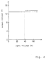
- Fig. 2 is a graph showing one example of an input/output characteristic of the DC-DC convertor.
- the DC-DC convertor 6 is intended to regulate an output voltage by monitoring the output voltage of the low voltage power VR and to control the switching condition on the high voltage side so that the output voltage is not excessively large or insufficient. Accordingly, even when the output voltage of the running power source 2 (input voltage of the DC-DC convertor) is reduced, for example, from 60 V to about 40 V, the output voltage of the low voltage power VR is regulated, for example, at 13.5 V.
- the DC-DC convertor 6 is so constructed that when the output voltage of the running power source 2 (input voltage of the DC-DC convertor) is reduced, for example, to 40 V or less, the output of the low voltage power VR is stopped.
- the maximum output voltage of the DC-DC convertor 6 is set to be slightly larger than an average power consumption of the low voltage loads 5.
- the low voltage battery 7 has a capacity smaller than that of one of the secondary batteries constituting the running power source 2 (for example, about 1/10 of the battery capacity of the running power source).
- the low voltage secondary battery 7 is charged by receiving the output voltage of the DC-DC convertor 6 through a counterflow preventive diode 14. It is to be noted that the counterflow preventive diode 14 may be provided in the DC-DC convertor 6.
- a power is supplied from the cathode side of the counterflow preventive diode 14 to the low voltage loads 5 through the breaking means 8.
- the underpower is supplied from the low voltage secondary battery 7 to the low voltage loads 5.
- the breaking means 8 is composed of a relay.
- the low voltage power VR outputted from the DC-DC convertor 6 is applied to an exciting winding 8a of the relay, and the supply/breaking of a power to the low voltage loads 5 is performed through a normally-open contact 8b of the relay.
- the main switch 9 is composed of a key switch and the like.
- a voltage for example, 12 V
- the DC-DC convertor 6 is operated to output the low voltage power VR when a specified voltage (for example, 12 V) is thus supplied to the starting control input terminal ST.
- the low voltage power VR is supplied to the operation control unit 12 as one of the low voltage loads 5 through the counterflow preventive diode 14 and the contact 8b of the relay in the breaking means 8, so that the electric vehicle 1 is turned in the operable state.
- a switch having a low withstand voltage can be used in this embodiment because a relatively low voltage is supplied to the starting control input terminal ST of the DC-DC converter 6 through a main switch 9 for starting the DC-DC converter 6.
- the charger 10 outputs a charging DC power VJ by voltage transformation and rectification of a commercial power.
- the charging DC power VJ is supplied to the running power source 2 through a running power source charging diode 16.
- the charger 10 includes a function of controlling the output voltage and the output current.
- the charger 10 certainly charges the running power source 2 and also prevents over-charge of the running power source 2 by checking the charging state of the running power source 2 through monitoring the output current and controlling the output voltage and output current on the basis of the charging state.
- the charge interface circuit 11 includes a simplified constant voltage circuit 17, an on-charge DC-DC convertor starting circuit 18, and a charging state information transmitting circuit 19.
- the simplified constant voltage circuit 17 outputs a DC voltage VK required for starting the DC-DC convertor 6.
- the on-charge DC-DC convertor starting circuit 18 is composed of a counterflow preventive diode.
- the starting DC voltage VK is supplied to the starting control input terminal ST of the DC-DC convertor 6 through the on-charge DC-DC convertor starting circuit (counterflow preventive diode). This allows the DC-DC convertor 6 to be started even when the main switch 9 is in the off-state, to thereby charge the low voltage secondary battery 7 by the output from the DC-DC convertor 6.
- the charging state information transmitting circuit 19 is composed of a power separating type signal transmitting circuit such as a photocoupler.
- a current is made to flow in a photodiode on the basis of the output voltage VK from the simplified constant voltage circuit 17, to turn on a phototransistor thereby controlling a charging state information input terminal 12b of the operation control unit 12 at an L level.
- the operation control unit 12 stops the operation of the electric vehicle 1 in the charging state by stopping the operation control.
- the operation control unit 12 in a normal operating state checks the mechanically rotational position of a rotor of the running motor 3 on the basis of the output from a rotor angle sensor 3K; to determine an energizing timing to each winding of the running motor 3; and further it produces and outputs the switching command signal 12a subjected to pulse width modulation (PWM) in accordance with a throttle opening degree detected by a throttle opening, degree sensor 12T, to thereby adjust the output from the running motor 3.
- PWM pulse width modulation
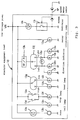
- Fig. 3 is a circuit diagram showing examples of electric equipment loads.
- Examples of the electric equipment loads include a horn 13b operated by a horn switch 13a; a tail lamp 13c; a stop lamp 13f connected in series to switches 13d, 13e closed in accordance with braking operation; a high beam head lamp 13h and a low beam head lamp 13i lit through a beam switch 13g; winker lamps 13l to 13p flashed by a winker timer 13k on the basis of operation of a winker switch 13j; a meter illuminating lamp 13q; and a light emitting diode 13s for indicating an over-speed, which is lit through a switch 13r closed when a vehicular speed detected through a speed meter cable SP is more than a specified value.
- the tail lamp 13c either of the head lamp 13h and 13i, and the meter illuminating lamp 13q are usually lit when the main switch 2 is operated to output the low voltage power VR and the low voltage power VR thus outputted is supplied through the breaking means 8 to the electric equipment loads 13.
- the winker lamps 13n and 13o on the right side are flashed and also the indicator lamp 13p for indicating the winker operation is flashed.
- a current is also supplied to the winker lamps 13l and 13m on the left side through the indicator lamp 13p; however, the winker lamps 13l and 13m are not lit because the indicator lamp 13p is small in power consumption (for example, 3.4 watt) and high in resistance and thereby a voltage generated across each of the winker lamps 13l and 13m (each power consumption: 10 watt) on the left side is low.
- the winker switch 13j is switched on the left side, the winker lamps 13l and 13m, and the indicator lamp 13p on the left side are flashed, while the winker lamps 13n and 13p on the right side are not lit.
- a starting power for example, a voltage equivalent to that of one of the secondary batteries
- the running power source 2 for example, a voltage equivalent to that of one of the secondary batteries
- the low voltage power VR is supplied to the exciting winding 8a of the relay constituting the breaking means 8, and the normally-open contact 8b of the relay is closed.
- the low voltage power VR is thus supplied to the operation control unit 12 and the electric equipment loads 13, thus turning the electric vehicle in the operable state.
- the battery capacity of the running power source 2 is reduced because the supply of a power to the low voltage loads 5 (operation control unit 12 and electric equipment loads 13) through the DC-DC convertor 6 is continued.
- a voltage to be supplied to the primary side (terminal HVI and HVG) of the DC-DC convertor 6 is reduced.
- the DC-DC convertor 6 stops the output of the low voltage power VR.
- the normally-open contact 8b of the relay constituting the breaking means 8 is thus turned in the open state, to thereby stop, the supply of a power from the low voltage secondary battery 7 to the low voltage loads 5.
- the stopping of the output of the low voltage power VR reduces the power consumption of the primary side of the DC-DC convertor 6, that is, the supply of a power from the running power source 2.
- Fig. 4 is a circuit diagram showing another example of the breaking means.
- a breaking means 20 shown in Fig. 4 uses semiconductor switching elements such as transistors in place of the relay.
- a base current is supplied to an NPN type transistor 22 through a base resistor 21, to turn on the NPN type transistor 22, and it also flows in a PNP type transistor 24 through a base resistor 23, to turn on the PNP type transistor 24, thus supplying a power to the low voltage loads 5.
- a phototransistor constituting a charging state information transmitting circuit 19 is turned on, the base-emitter of the NPN type transistor 22 is short-circuited, to turn off the transistors 22 and 24, thus stopping the supply of a power to the low voltage loads 5.
- the charging of the low voltage secondary battery 7 by the output of the low voltage power from the DC-DC convertor 6 can be effectively performed by stopping the supply of a power to the low voltage loads 5 in the charging state.
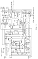
- Fig. 5 is a circuit diagram showing another example of the DC-DC convertor.
- a DC-DC convertor 60 shown in Fig. 5 contains the counterflow preventive diode 14 and includes an output terminal VRD connected to the counterflow preventive diode 14.
- the DC-DC convertor 60 includes a starting control unit 61, a power source portion 62, a convertor main body 63, and a voltage reduction detecting means 64.
- a starting power for example, 12 V
- a base current is supplied to a starting transistor (PNP type transistor) Q1 by way of an emitter-base, resistor R1 and capacitor C1 during a time constant set by the resistor R1 and capacitor C1.
- the starting transistor Q1 is turned on during the base current is supplied, and the base current is supplied to an NPN type transistor Q2 through a resistor R2.
- a diode D1 is provided for releasing charges of the capacitor C1 when the supply of the starting power is stopped.
- a constant voltage diode Z1 is of a type in which a breakdown voltage is, for example, about 9 V.
- a base current flows in a PNP type transistor Q3 through a base resistor R3, the constant voltage diode Z1 and the NPN type transistor Q2, and thereby the PNP type transistor Q3 is turned on.
- the PNP type transistor Q3 When the PNP type transistor Q3 is turned on, the NPN type transistor Q2 and PNP transistor Q3 are kept in the on-state even when the starting transistor Q1 is turned off because a base current is supplied from the collector side of the PNP type transistor Q3 to the NPN type transistor Q2 through a feedback resistor R4.
- a base current is supplied to an NPN type transistor Q4 through a base resistor R5 and thereby the NPN type transistor Q4 is turned on and is connected to a constant voltage diode Z2.
- the breakdown voltage of the constant voltage diode Z2 is set at, for example, about 6 V. Accordingly, after the PNP type transistor Q3 is turned on, the NPN type transistor Q2 and PNP type transistor Q3 are kept in the on-state even when a voltage supplied to the starting control input terminal ST is reduced, for example, to about 7 V.
- a base current flows in a NPN type transistor Q5 provided for stopping the starting operating, through a current limiting resistor R6, a constant voltage diode Z3 for detecting over-voltage upon starting control, and a counterflow preventive diode D2, and thereby the NPN type transistor Q5 is turned on, to short-circuit the base-emitter of the NPN type transistor Q2 provided for driving the starting operation, thereby preventing the drive of the starting operation.
- the PNP type transistor Q3 When the PNP type transistor Q3 is turned on, a base current flows through a base resistor R7 in an NPN type transistor Q6 provided for driving a high voltage power source, to thereby turn on the NPN type transistor Q6, and a base current flows in a PNP type transistor Q7 provided for turning on a high voltage power source, through the NPN type transistor Q6. As a result, the PNP type transistor Q7 is turned on, so that a high voltage power (for example, 60 V) of the running power source supplied to the terminal HV1 flows in the power source portion 62.
- a high voltage power for example, 60 V
- the power source portion 62 includes a simplified constant voltage circuit having a bleeder resistor R11, an NPN type transistor Q11, a resistor R12, and a constant voltage diode Z11; and a regulated power source circuit U11 using a three-terminal regulator IC.
- a high voltage (for example, 60 V) of the running power source is reduced by the bleeder resistor R11, and is adjusted into, for example, about 20 to 25 V in the simplified constant voltage circuit using the NPN type transistor Q11.
- the output voltage is further regulated, for example, into about 15 V in the regulated power source circuit U11.
- the output voltage thus regulated is supplied to a switching control portion 67.
- the convertor main body 63 includes a transformer T21; a field effect transistor Q21 for switching a power of the running power source supplied to a primary winding T21a of the transformer T21; a current detecting resistor R21; rectifying diodes D21, D22 for rectifying an AC voltage generated at a secondary winding T21b of the transformer T21; a choke coil L21, a smoothing capacitor C21; the counterflow preventive diode 14; an output voltage detecting circuit 65; an isolator 66; and the switching control portion 67.
- the switching control portion 67 When a regulated power (for example, about 15 V) is supplied from the power source portion 62, the switching control portion 67 outputs a switching command signal 67a subjected to specified pulse width modulation (PWM) at a predetermined repeated period (switching frequency).
- PWM pulse width modulation
- the PWM switching command signal 67a is supplied to a gate of the field effect transistor Q21 through a gate resistor R22.
- the field effect transistor Q21 switches, on the basis of the PWM switching command signal 67a, a current flowing the primary winding T21a of the transformer T21, to generate an AC voltage corresponding to the winding ratio of the transformer T21 at the secondary winding T21b of the transformer T21.
- the AC voltage generated at the secondary winding T21b is rectified by the rectifying diodes D21, D22, followed by smoothing by the choke coil L21 and the smoothing capacitor C21, to output a low voltage power VR (low voltage DC voltage) between output terminals VRO and VRG.
- the low voltage power VR is also outputted between the output terminals VRD and VRG through the counterflow preventive diode 14.
- the output voltage detecting circuit 65 detects the output voltage of the low voltage power VR, and produces a signal having a pulse width or pulse period depending on the detected output voltage, or a signal having a pulse width or pulse period depending on a difference (deviation) between a predetermined rated voltage and the output voltage.
- the pulse signal 65a outputted from the output voltage detecting circuit 65 is transmitted to the switching control portion 67 through the isolator (power separating type signal transmitting circuit) 66 using a photocoupler or the like.
- the switching control portion 67 performs a feedback control of the pulse width of the PWM switching command signal 67a so that the output voltage of the low voltage power VR is within a specified voltage (for example, 13.5 ⁇ 1.5 V) on the basis of the information on the output voltage supplied through the isolator 66 or a difference (deviation) between the output voltage and the predetermined rated voltage.
- a specified voltage for example, 13.5 ⁇ 1.5 V
- the switching control portion 67 monitors whether or not the field effect transistor Q21 is normally operated on the basis of the voltage generated at the end of the current detecting resistor R21; and also adjusts the pulse width of the PWM switching command signal 67a in accordance with the value of the switching current for adjusting a power supplied to the low voltage side through the transformer T21, and controls a current on the primary side not to be made excessively large.
- the current reduction detecting circuit 64 includes a current limiting resistor 64a, a constant voltage diode 64b, and a photodiode 64c of a photocoupler.
- a voltage of the low voltage power VR is reduced, for example, to 10 V or less, a current is not allowed to flow in the photodiode 64c and thereby a phototransistor 64d provided on the starting control portion 61 side is turned off.
- a capacitor 64f is started through a resistor 64e, and when the voltage of the capacitor 64f is increased to a specified value (about 1.3 V in this embodiment), a base current flows in the NPN type transistor Q5 provided for stopping the starting operation, by way of a resistor 64g and the counterflow preventive diode D3, and thereby the NPN type transistor Q5 is turned on, thus short-circuiting the base-emitter of the NPN type transistor Q2 for driving the starting operation.
- a specified value about 1.3 V in this embodiment
- the NPN type transistor Q2 for driving the starting control, PNP type transistor Q3, NPN type transistor Q6 for driving a high voltage power, and PNP type transistor Q7 for turning on a high voltage power are all turned off, to thereby stop the operation of the DC-DC convertor 60.
- Fig. 5 shows the configuration in which the starting operation of the starting control portion 61 is stopped on the basis of the reduction in the output voltage of the DC-DC convertor main body 63; however, the switching control portion 67 may have a function of stopping the operation of the DC-DC convertor 60. Specifically, even when the pulse width of the PWM switching command signal 67a is subjected to feedback control so that the output voltage of the low voltage power VR is set at a value in a specified range (for example, 13.5 ⁇ 1.5 V) on the basis of information on the output voltage supplied through the isolator or a difference (deviation) between the output voltage and the rated voltage, there may occur a state that the output voltage is out of the specified range is continued for a specified time.
- a specified range for example, 13.5 ⁇ 1.5 V
- the battery capacity of the running power source 2 is judged to be reduced, and a pulse signal (not shown) is outputted from the switching control portion 67 for allowing a base current to flow in the NPN type transistor Q5 provided for stopping the starting operation, thereby stopping the operation of the DC-DC convertor.
- a voltage supplied to the power source portion 62 through the PNP type transistor Q7 provided for turning on a high voltage power in the starting control unit 61 is monitored by a voltage monitoring circuit (not shown), and when the voltage is for example more than 50 V, the switching control is started; however, when the switching control is started and then a state that the voltage is less than 40 V is continued for a specified time, the output of the PWM switching command signal 67a is stopped, to thereby stop the operation of the DC-DC convertor 60.
- the counterflow preventive diode 14 shown in Figs. 1 and 5 is provided for preventing the detection of the output voltage of the DC-DC convertor from being obstructed by the supply of a voltage of the low voltage secondary battery 8 to the DC-DC convertor 5 side.
- the output voltage detecting circuit 65 in the convertor main body 63 may be so constructed that the output voltage of the low voltage power is detected on the basis of an DC voltage obtained by rectifying an AC voltage generated at the secondary winding T21b of the transformer T21 using a different rectifying circuit (not shown), to thereby eliminate the necessity of provision of the counterflow preventive diode 14 in a power supply passage to the low voltage loads 5.
- the DC-DC convertor 60 shown in Fig. 5 can be restarted from the inoperative state by turning off the main switch 9 and then turning on it again.
- the stopping of the operation of the DC-DC convertor 60 is intended to be performed for preventing the running power source 2 from being over-discharged by leaving the main switch 9 in the on-state, and accordingly the reduced battery capacity of the running power source 2 is desirable to be charged as early as possible.
- the DC-DC convertor 6 is easily re-started by turning on the main switch 9 again and the electric vehicle comes to be in the operable state, the driver often does not sufficiently recognize the fact that the battery capacity of the running power source 2 is reduced.
- the DC-DC convertor 6 may be so constructed as not to be started by turning on the main switch 9 again but to be started by operating a returning device composed of a switch or the like operated after opening a hide cover provided in a location different from an ordinary operating unit or in the operating unit.
- a low voltage power obtained by conversion from a high voltage power of a running power source composed of a secondary battery by a DC-DC convertor is supplied to an operation control unit and electric equipment loads such as a lamp and is also used to charge a low voltage secondary battery, in which the running power source and the low voltage secondary battery are prevented from being over-discharged even when a main switch is left in the on-state.
- a low voltage power VR outputted from a DC-DC convertor 6 is supplied to an exciting winding 8a of a relay and is also supplied to a low voltage secondary battery 7 through a diode 14.
- the low voltage power VR is supplied to low voltage loads 5 through a contact 8b of the relay.
- the DC-DC convertor 6 is so constructed that the output of the low voltage power is stopped when the output voltage is reduced to a value less than a specified range due to the reduction in the battery capacity of the running power source 2. In the case where the battery capacity of the running power source 2 is reduced when the main switch 9 is left in the on-state, the output of the DC-DC convertor 6 is stopped, and the contact 8b of the relay is opened for preventing over-discharge of the low voltage secondary battery 7.
Abstract
Description
- The present invention relates to an electric vehicle including a high voltage chargeable running battery for supplying a power to a running motor; a step-down type DC-DC convertor; low voltage loads (such as an operation control unit and various electric equipment loads, each of which is operated at a low voltage); and a low voltage secondary battery for supplying a power to the low voltage loads; wherein a power of the running battery is supplied to the low voltage loads and is used for charging the low voltage secondary battery through the DC-DC convertor. In particular, the present invention concerns an apparatus for preventing over-discharge of a battery used for an electric vehicle, which prevents over-discharge of both the running power source and the low voltage secondary battery by stopping the operation of the DC-DC convertor under a specified condition and breaking the supply of a power from the low voltage secondary battery to the low voltage loads.
- Japanese Patent Laid-open No. Hei 6-133401 discloses an electric vehicle in which a low voltage power for electric equipment is obtained by conversion from a high voltage power of a running secondary battery using a step-down type DC-DC convertor, and a secondary battery is provided on the low voltage output side of the DC-DC convertor.
- Fig. 6 is a block diagram showing the configuration of an electric vehicle disclosed in Japanese Patent Laid-open No. Hei 6-133401. An
electric vehicle 100 is so constructed that a DC power of a runningpower source 101 composed of a secondary battery is converted into an AC power by acontroller 102 and supplied to a three-phase motor 103, and a rotational output of themotor 103 is transmitted to a drivingrear wheel 105 through atransmission 104. - The
electric vehicle 100 includes a DC-DC convertor 107 for supplying a low voltage power (for example, 12 V) toelectric equipment loads 106 including ahead lamp 106a, ahorn 106b, and a tail/stop lamp 106c. Amain switch 108 of the DC-DC convertor 107 is composed of aninput side switch 108a and anoutput side switch 108b interlocked with each other. When themain switch 108 is turned on, a power of therunning power source 101 is supplied to the input side of the DC-DC convertor 107 through theinput side switch 108a and a step-down DC power is outputted from the output side of the DC-DC convertor 107. The step-down DC power thus obtained is supplied to theelectric equipment loads 106 through theoutput side switch 108b and it also supplied to an exciting winding of amain relay 109 through a normally-closed contact of arelay 114 in acharger 111 for operating themain relay 109. A power of the runningpower source 101 is supplied to thecontroller 102 by operation of themain relay 109, and thecontroller 102 comes to be in the operating state. Thecontroller 102, including an invertor, controls the operation of themotor 103 on the basis of a throttle opening degree θTH. - The capacity of the DC-
DC convertor 107 of theelectric vehicle 100 is made small by provision of a low voltagesecondary battery 110 on the output side of the DC-DC convertor 107. A current applied to theelectric equipment loads 106 is temporarily increased when a lamp, buzzer and the like are all operated at once. At this time, an underpower is supplied from thesecondary battery 110. The output capacity of the DC-DC convertor 107 is set to be larger than an average power consumption of theelectric equipment loads 106 and to charge thesecondary battery 110 in the state of such an average power consumption. - The
electric vehicle 100 includes acharger 111. When apower source plug 112 of thecharger 111 is plugged in a commercial power source receptacle, a DC power rectified in full-wave and controlled in current and voltage through a charge control means 113 is supplied to the runningpower source 101, to charge the runningpower source 101. In addition, the contact of therelay 114 provided in thecharger 111 is opened in such a charging state, to break the energization to the exciting winding of themain relay 109, so that the supply of a power to thecontroller 102 is prevented even when themain switch 108 is in the on-state. - When the
main switch 108 is left in the on-state, there is a fear that the secondary battery of the runningpower source 101 is over-discharged (emptied) because the supply of a power to theelectric equipment loads 106 through the DC-DC convertor 107 is continued. On the other hand, when the output voltage of the DC-DC convertor is reduced along with a reduction in the battery capacity of the running power source, there is a fear that the low voltagesecondary battery 110 is over-discharged because the supply of a power from the low voltagesecondary battery 110 to the low voltage loads is continued. In some cases, the secondary battery is significantly reduced in the service life by over-discharge and the secondary battery thus over-discharged cannot exhibit the original performance even by charging it again. - A technique of preventing over-discharge of a battery caused when a main switch is left in the on-state, has been disclosed in Japanese Patent Laid-open Nos. Hei 6-197462 and Hei 5-205781, in which a voltage of a running power source is monitored and a switching means interposed between the running power source and a load is controlled to be broken when the voltage of the running power source is lowered to a predetermined threshold voltage.
- The over-discharge preventive circuit for the secondary battery proposed in Japanese Patent Laid-open No. Hei 6-197462 monitors a voltage of the secondary battery using a Zener diode and controls the supply/breaking of a power by an electronically switching means using a transistor or the like. This circuit is also intended to regulate the supply/breaking of a power by setting a breaking voltage of the power source to be lower than a power supply starting voltage of the power source.
- The over-discharge preventive apparatus proposed in Japanese Patent Laid-open No. Hei 5-205781 detects a discharge current of a battery and changes a threshold voltage for over-discharge of the battery on the basis of the detected discharge current. A terminal voltage of the secondary battery is significantly changed depending on a discharge current. When a load applied to an electric vehicle is large, for example, upon quick starting or ascending along a slope, a discharge current becomes large and thereby the terminal voltage of the secondary battery is lowered. For this reason, this apparatus is intended to effectively use the capacity of the secondary battery and to certainly prevent over-discharge by changing a threshold voltage for over-discharge depending on a discharge current.
- A technique of preventing over-discharge of a battery when a driver is not in an electric car, has been disclosed in Japanese Utility-model Laid-open No. Sho 63-21401 and Japanese Patent Laid-open No. Hei 4-145811.
- An apparatus for preventing a power source switch from being left in the on-state in a battery type vehicle, proposed in Japanese Utility-model Laid-open No. Sho 63-21401, includes a means for detecting whether or not a driver is in the vehicle, in which a power source breaking switch is controlled to be turned off after an elapse of a specified time since the driver is get out of the vehicle.
- A driving apparatus for an electric car driven by vector control of a motor, proposed in Japanese Patent Laid-open No. Hei 4-145811, is intended to prevent overdischarge of a battery even when a driver is get out of the vehicle with a shift lever left in a D range by setting an exciting current command value of the motor at zero when the absence of the driver is detected.
- The above over-discharge preventive apparatus described in the related art, however, is disadvantageous in that since a switching means for breaking the supply of a power is provided between a relatively high voltage running power source and a load, it requires a high withstand voltage. Another disadvantage is that since the apparatus is so constructed as to monitor a voltage of a running power source having a terminal voltage largely varied due to a running state, it requires a special circuit configuration in which, for example, a hysteresis characteristic is provided between an energization enabling voltage and a breaking voltage or a threshold voltage is changed depending on an amount of a discharge current, to thereby complicate the circuit configuration.
- The above configuration of stopping the supply of an unnecessary power when the absence of a driver is confirmed, described in the related art, requires a means for detecting whether or not the driver is in the vehicle, thus complicating the apparatus.
- The present invention has been made to solve the above-described problems, and an object of the present invention is to provide an apparatus for preventing overdischarge of a battery used for an electric vehicle, which is capable of simplifying a circuit configuration by detecting a reduction in a battery capacity of a running power source using an output voltage regulating function of a DC-DC convertor without provision of a special circuit for detecting the reduction in the battery capacity of the running power source; and which is capable of preventing over-discharge of the running power source and a low voltage secondary battery using a switching means having a low withstand voltage.
- To achieve the above object, according to a preferred mode of the present invention, there is provided an apparatus for preventing over-discharge of a battery used for an electric vehicle, including:
- a high voltage running power source composed of a secondary battery;
- a DC-DC convertor for receiving a power from the running power source and outputting a low voltage power, which is adapted to stop the output of the low voltage power when the output voltage of the low voltage power cannot be kept within a specified voltage range;
- a low voltage load driven by the low voltage power outputted from the DC-DC convertor;
- a low voltage secondary battery charged by the output voltage from the DC-DC convertor and supplying a power to the low voltage load; and
- a breaking means for breaking the supply of a power from the low voltage secondary battery to the low voltage load on the basis of stopping of the output of the low voltage power from the DC-DC convertor.
- According to the apparatus of the present invention, when the supply of a power to a DC-DC convertor is reduced along with a reduction in a battery capacity of a running power source, the output of a low voltage power from the DC-DC convertor is stopped. A breaking means breaks the supply of a power from a low voltage secondary battery to low voltage loads on the basis of stopping of the output of the low voltage power, to thereby prevent over-discharge of the low voltage secondary battery. Since a power consumption of the DC-DC convertor is reduced by stopping of the output of the low voltage power from the DC-DC convertor, a power consumption of the running power source is reduced, thus preventing over-discharge of the running power source.
- As described above, the apparatus for preventing over-discharge of a battery used for an electric vehicle according to Claim 1 includes a DC-DC convertor for receiving a power from the running power source and outputting a low voltage power, which is adapted to stop the output of the low voltage power when the output voltage of the low voltage power cannot be kept within a specified voltage range; and a breaking means for breaking the supply of a power from the low voltage secondary battery to the low voltage load on the basis of stopping of the output of the low voltage power from the DC-DC convertor. This makes it possible to prevent over-discharge of the low voltage secondary battery. Moreover, since a power consumption of the DC-DC convertor is reduced by stopping of the output of the low voltage power from the DC-DC convertor, a power consumption of the running power source is reduced, thus preventing over-discharge of the running power source.
- The breaking means in the above apparatus is preferably composed of a relay having an exciting winding to which the output voltage from the DC-DC convertor is supplied and a normally-open contact through which the supply of a power to the low voltage load is controlled.
- In the above apparatus, the breaking means can be composed of a relay driven by the output voltage of a DC-DC convertor in which the supply of a power to low voltage loads is controlled through a normally-open contact of the relay, and accordingly it becomes possible to simplify the configuration of the breaking means.
- Hereinafter, embodiments of the present invention will be described with reference to the drawings.
- Fig. 1
is a block diagram showing an electric system of an electric vehicle including a battery over-discharge preventive apparatus of the present invention. - Fig. 2
is a graph showing one example of an input-output characteristic of a DC-DC convertor. - Fig. 3
is a circuit diagram showing examples of electric equipment loads. - Fig. 4
is a circuit diagram showing a breaking means different from that shown in Fig. 1. - Fig. 5
is a circuit diagram showing a DC-DC convertor different from that shown in Fig. 1. - Fig. 6
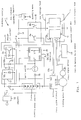
is a block diagram of a related art electric vehicle. - Fig. 1 is a block diagram showing an electric system of an electric vehicle including an apparatus for preventing over-discharge of a battery according to the present invention.
- An electric system 1 of an electric vehicle includes: a running
power source 2; amotor drive circuit 4 for supplying an AC power to each winding of a runningmotor 3; a DC-DC convertor 6 for receiving a power from the runningpower source 2 and supplying a low voltage power VR tolow voltage loads 5; a low voltagesecondary battery 7; a breaking means 8 for breaking the supply of a power to thelow voltage loads 5; amain switch 9; acharger 10; and a charge interface circuit (charge I/F circuit) 11. Thelow voltage loads 5 include anoperation control unit 12 and electric equipment loads 13. - The running
power source 2 includes a plurality (for example, five pieces) of secondary batteries, each having a specified rated output voltage (for example, 12 V), which are connected in series for supplying a high DC voltage (for example, 60 V). - A three-phase ,brushless servo-motor is used as the running
motor 3. Themotor drive circuit 4 includes an invertor for converting a DC power supplied from the runningpower source 2 into an AC power and supplying the AC power to the runningmotor 3. Themotor drive circuit 4 switches a plurality of switching elements constituting the invertor on the basis of a switchingcommand signal 12a supplied from theoperation control unit 12, to supply a power to each winding of the runningmotor 3 for rotating the runningmotor 3. In addition, the low voltage power VR is dependent from the runningpower source 2 in this embodiment, the switchingcommand signal 12a outputted from theoperation control unit 12 is transmitted to themotor drive circuit 4 side through a power separating type signal transmission circuit (not shown) such as a photocoupler. - A switching regulator of an input-output isolating type is used as the DC-
DC convertor 6. The DC-DC convertor 6 starts DC-DC conversion when a specified voltage is supplied to a starting control input terminal ST. In Fig. 1, reference characters HVI and HVG indicate input terminals of a high voltage power side, and VRO and VRG indicate output terminals of a low voltage power VR side. - Fig. 2 is a graph showing one example of an input/output characteristic of the DC-DC convertor. The DC-
DC convertor 6 is intended to regulate an output voltage by monitoring the output voltage of the low voltage power VR and to control the switching condition on the high voltage side so that the output voltage is not excessively large or insufficient. Accordingly, even when the output voltage of the running power source 2 (input voltage of the DC-DC convertor) is reduced, for example, from 60 V to about 40 V, the output voltage of the low voltage power VR is regulated, for example, at 13.5 V. The DC-DC convertor 6 is so constructed that when the output voltage of the running power source 2 (input voltage of the DC-DC convertor) is reduced, for example, to 40 V or less, the output of the low voltage power VR is stopped. The maximum output voltage of the DC-DC convertor 6 is set to be slightly larger than an average power consumption of the low voltage loads 5. - The
low voltage battery 7 has a capacity smaller than that of one of the secondary batteries constituting the running power source 2 (for example, about 1/10 of the battery capacity of the running power source). The low voltagesecondary battery 7 is charged by receiving the output voltage of the DC-DC convertor 6 through a counterflowpreventive diode 14. It is to be noted that the counterflowpreventive diode 14 may be provided in the DC-DC convertor 6. - A power is supplied from the cathode side of the counterflow
preventive diode 14 to thelow voltage loads 5 through the breaking means 8. When the power consumption of thelow voltage loads 5 becomes temporarily large to such an extent as to exceed the maximum output power of the DC-DC convertor 6, the underpower is supplied from the low voltagesecondary battery 7 to the low voltage loads 5. - The breaking means 8 is composed of a relay. The low voltage power VR outputted from the DC-
DC convertor 6 is applied to an exciting winding 8a of the relay, and the supply/breaking of a power to thelow voltage loads 5 is performed through a normally-open contact 8b of the relay. - The
main switch 9 is composed of a key switch and the like. When themain switch 9 is turned on, a voltage (for example, 12 V) equivalent to that of one of the secondary batteries of the runningpower source 2 is supplied to the starting control input terminal ST of the DC-DC convertor 6 through the counterflowpreventive diode 14. The DC-DC convertor 6 is operated to output the low voltage power VR when a specified voltage (for example, 12 V) is thus supplied to the starting control input terminal ST. The low voltage power VR is supplied to theoperation control unit 12 as one of thelow voltage loads 5 through the counterflowpreventive diode 14 and thecontact 8b of the relay in the breaking means 8, so that the electric vehicle 1 is turned in the operable state. - A switch having a low withstand voltage can be used in this embodiment because a relatively low voltage is supplied to the starting control input terminal ST of the DC-
DC converter 6 through amain switch 9 for starting the DC-DC converter 6. - The
charger 10 outputs a charging DC power VJ by voltage transformation and rectification of a commercial power. The charging DC power VJ is supplied to the runningpower source 2 through a running powersource charging diode 16. Thecharger 10 includes a function of controlling the output voltage and the output current. Thecharger 10 certainly charges the runningpower source 2 and also prevents over-charge of the runningpower source 2 by checking the charging state of the runningpower source 2 through monitoring the output current and controlling the output voltage and output current on the basis of the charging state. - The
charge interface circuit 11 includes a simplifiedconstant voltage circuit 17, an on-charge DC-DCconvertor starting circuit 18, and a charging stateinformation transmitting circuit 19. The simplifiedconstant voltage circuit 17 outputs a DC voltage VK required for starting the DC-DC convertor 6. - The on-charge DC-DC
convertor starting circuit 18 is composed of a counterflow preventive diode. The starting DC voltage VK is supplied to the starting control input terminal ST of the DC-DC convertor 6 through the on-charge DC-DC convertor starting circuit (counterflow preventive diode). This allows the DC-DC convertor 6 to be started even when themain switch 9 is in the off-state, to thereby charge the low voltagesecondary battery 7 by the output from the DC-DC convertor 6. - The charging state
information transmitting circuit 19 is composed of a power separating type signal transmitting circuit such as a photocoupler. In this embodiment, a current is made to flow in a photodiode on the basis of the output voltage VK from the simplifiedconstant voltage circuit 17, to turn on a phototransistor thereby controlling a charging state information input terminal 12b of theoperation control unit 12 at an L level. When the charging stateinformation input terminal 12b becomes the L level, theoperation control unit 12 stops the operation of the electric vehicle 1 in the charging state by stopping the operation control. - The
operation control unit 12 in a normal operating state checks the mechanically rotational position of a rotor of the runningmotor 3 on the basis of the output from arotor angle sensor 3K; to determine an energizing timing to each winding of the runningmotor 3; and further it produces and outputs the switchingcommand signal 12a subjected to pulse width modulation (PWM) in accordance with a throttle opening degree detected by a throttle opening,degree sensor 12T, to thereby adjust the output from the runningmotor 3. - Fig. 3 is a circuit diagram showing examples of electric equipment loads.
- Examples of the electric equipment loads include a
horn 13b operated by ahorn switch 13a; atail lamp 13c; astop lamp 13f connected in series toswitches beam switch 13g; winker lamps 13ℓ to 13p flashed by awinker timer 13k on the basis of operation of awinker switch 13j; ameter illuminating lamp 13q; and alight emitting diode 13s for indicating an over-speed, which is lit through aswitch 13r closed when a vehicular speed detected through a speed meter cable SP is more than a specified value. Thetail lamp 13c, either of the head lamp 13h and 13i, and themeter illuminating lamp 13q are usually lit when themain switch 2 is operated to output the low voltage power VR and the low voltage power VR thus outputted is supplied through the breaking means 8 to the electric equipment loads 13. - When the
winker switch 13j is switched from the neutral position to the right side, the winker lamps 13n and 13o on the right side are flashed and also theindicator lamp 13p for indicating the winker operation is flashed. In this case, a current is also supplied to thewinker lamps 13ℓ and 13m on the left side through theindicator lamp 13p; however, thewinker lamps 13ℓ and 13m are not lit because theindicator lamp 13p is small in power consumption (for example, 3.4 watt) and high in resistance and thereby a voltage generated across each of thewinker lamps 13ℓ and 13m (each power consumption: 10 watt) on the left side is low. Similarly, when thewinker switch 13j is switched on the left side, thewinker lamps 13ℓ and 13m, and theindicator lamp 13p on the left side are flashed, while thewinker lamps 13n and 13p on the right side are not lit. - Next, the operation of the electric vehicle shown in Fig. 1 will be described. When the
main switch 9 is turned on, a starting power (for example, a voltage equivalent to that of one of the secondary batteries) is supplied from the runningpower source 2 to the starting control input terminal ST of the DC-DC convertor 6, so that the DC-DC convertor 6 is operated to output the low voltage power VR. - The low voltage power VR is supplied to the exciting winding 8a of the relay constituting the breaking means 8, and the normally-
open contact 8b of the relay is closed. The low voltage power VR is thus supplied to theoperation control unit 12 and the electric equipment loads 13, thus turning the electric vehicle in the operable state. - When the
main switch 9 is left in the on-state, the battery capacity of the runningpower source 2 is reduced because the supply of a power to the low voltage loads 5 (operation control unit 12 and electric equipment loads 13) through the DC-DC convertor 6 is continued. As a result, a voltage to be supplied to the primary side (terminal HVI and HVG) of the DC-DC convertor 6 is reduced. When a voltage supplied to the primary side is reduced, for example, to 40 V or less, the DC-DC convertor 6 stops the output of the low voltage power VR. The normally-open contact 8b of the relay constituting the breaking means 8 is thus turned in the open state, to thereby stop, the supply of a power from the low voltagesecondary battery 7 to the low voltage loads 5. The stopping of the output of the low voltage power VR reduces the power consumption of the primary side of the DC-DC convertor 6, that is, the supply of a power from the runningpower source 2. - When the electric vehicle is left in a state that the lamps are lit, there is a fear that the running
power source 2 is over-discharged because a large power is continuously supplied from the runningpower source 2 through the DC-DC convertor 6. In this embodiment, however, when a voltage supplied to the primary side of the DC-DC convertor 6 is reduced to a specified value along with a reduction in the battery capacity of the runningpower source 2, the DC-DC convertor 6 stops the output of the low voltage power VR, thus preventing the runningpower source 2 from being over-discharged; and further since the supply of a power from the low voltagesecondary battery 7 to thelow voltage loads 5 in the breaking state is also stopped, to thereby prevent the low voltagesecondary battery 7 from being over-discharged. - Fig. 4 is a circuit diagram showing another example of the breaking means.
- A breaking means 20 shown in Fig. 4 uses semiconductor switching elements such as transistors in place of the relay. When the low voltage power VR is outputted from the DC-
DC convertor 6, a base current is supplied to anNPN type transistor 22 through abase resistor 21, to turn on theNPN type transistor 22, and it also flows in aPNP type transistor 24 through a base resistor 23, to turn on thePNP type transistor 24, thus supplying a power to the low voltage loads 5. On the other hand, when a phototransistor constituting a charging stateinformation transmitting circuit 19 is turned on, the base-emitter of theNPN type transistor 22 is short-circuited, to turn off thetransistors secondary battery 7 by the output of the low voltage power from the DC-DC convertor 6 can be effectively performed by stopping the supply of a power to thelow voltage loads 5 in the charging state. - Fig. 5 is a circuit diagram showing another example of the DC-DC convertor.
- A DC-
DC convertor 60 shown in Fig. 5 contains the counterflowpreventive diode 14 and includes an output terminal VRD connected to the counterflowpreventive diode 14. The DC-DC convertor 60 includes a startingcontrol unit 61, apower source portion 62, a convertormain body 63, and a voltagereduction detecting means 64. - When a starting power (for example, 12 V) is supplied to a starting control input terminal ST, a base current is supplied to a starting transistor (PNP type transistor) Q1 by way of an emitter-base, resistor R1 and capacitor C1 during a time constant set by the resistor R1 and capacitor C1. The starting transistor Q1 is turned on during the base current is supplied, and the base current is supplied to an NPN type transistor Q2 through a resistor R2. A diode D1 is provided for releasing charges of the capacitor C1 when the supply of the starting power is stopped. A constant voltage diode Z1 is of a type in which a breakdown voltage is, for example, about 9 V. When a voltage supplied to the starting control input terminal ST is, for example, 10 V or more, a base current flows in a PNP type transistor Q3 through a base resistor R3, the constant voltage diode Z1 and the NPN type transistor Q2, and thereby the PNP type transistor Q3 is turned on.
- When the PNP type transistor Q3 is turned on, the NPN type transistor Q2 and PNP transistor Q3 are kept in the on-state even when the starting transistor Q1 is turned off because a base current is supplied from the collector side of the PNP type transistor Q3 to the NPN type transistor Q2 through a feedback resistor R4. When the PNP type transistor Q3 is turned on, a base current is supplied to an NPN type transistor Q4 through a base resistor R5 and thereby the NPN type transistor Q4 is turned on and is connected to a constant voltage diode Z2. The breakdown voltage of the constant voltage diode Z2 is set at, for example, about 6 V. Accordingly, after the PNP type transistor Q3 is turned on, the NPN type transistor Q2 and PNP type transistor Q3 are kept in the on-state even when a voltage supplied to the starting control input terminal ST is reduced, for example, to about 7 V.
- When a voltage (for example, 15 V or more) higher than a rated voltage is supplied to the starting control input terminal ST, a base current flows in a NPN type transistor Q5 provided for stopping the starting operating, through a current limiting resistor R6, a constant voltage diode Z3 for detecting over-voltage upon starting control, and a counterflow preventive diode D2, and thereby the NPN type transistor Q5 is turned on, to short-circuit the base-emitter of the NPN type transistor Q2 provided for driving the starting operation, thereby preventing the drive of the starting operation.
- When the PNP type transistor Q3 is turned on, a base current flows through a base resistor R7 in an NPN type transistor Q6 provided for driving a high voltage power source, to thereby turn on the NPN type transistor Q6, and a base current flows in a PNP type transistor Q7 provided for turning on a high voltage power source, through the NPN type transistor Q6. As a result, the PNP type transistor Q7 is turned on, so that a high voltage power (for example, 60 V) of the running power source supplied to the terminal HV1 flows in the
power source portion 62. - The
power source portion 62 includes a simplified constant voltage circuit having a bleeder resistor R11, an NPN type transistor Q11, a resistor R12, and a constant voltage diode Z11; and a regulated power source circuit U11 using a three-terminal regulator IC. A high voltage (for example, 60 V) of the running power source is reduced by the bleeder resistor R11, and is adjusted into, for example, about 20 to 25 V in the simplified constant voltage circuit using the NPN type transistor Q11. The output voltage is further regulated, for example, into about 15 V in the regulated power source circuit U11. The output voltage thus regulated is supplied to aswitching control portion 67. - The convertor
main body 63 includes a transformer T21; a field effect transistor Q21 for switching a power of the running power source supplied to a primary winding T21a of the transformer T21; a current detecting resistor R21; rectifying diodes D21, D22 for rectifying an AC voltage generated at a secondary winding T21b of the transformer T21; a choke coil L21, a smoothing capacitor C21; the counterflowpreventive diode 14; an outputvoltage detecting circuit 65; anisolator 66; and the switchingcontrol portion 67. - When a regulated power (for example, about 15 V) is supplied from the
power source portion 62, the switchingcontrol portion 67 outputs a switchingcommand signal 67a subjected to specified pulse width modulation (PWM) at a predetermined repeated period (switching frequency). The PWMswitching command signal 67a is supplied to a gate of the field effect transistor Q21 through a gate resistor R22. The field effect transistor Q21 switches, on the basis of the PWMswitching command signal 67a, a current flowing the primary winding T21a of the transformer T21, to generate an AC voltage corresponding to the winding ratio of the transformer T21 at the secondary winding T21b of the transformer T21. The AC voltage generated at the secondary winding T21b is rectified by the rectifying diodes D21, D22, followed by smoothing by the choke coil L21 and the smoothing capacitor C21, to output a low voltage power VR (low voltage DC voltage) between output terminals VRO and VRG. The low voltage power VR is also outputted between the output terminals VRD and VRG through the counterflowpreventive diode 14. - The output
voltage detecting circuit 65 detects the output voltage of the low voltage power VR, and produces a signal having a pulse width or pulse period depending on the detected output voltage, or a signal having a pulse width or pulse period depending on a difference (deviation) between a predetermined rated voltage and the output voltage. Thepulse signal 65a outputted from the outputvoltage detecting circuit 65 is transmitted to the switchingcontrol portion 67 through the isolator (power separating type signal transmitting circuit) 66 using a photocoupler or the like. - The switching
control portion 67 performs a feedback control of the pulse width of the PWMswitching command signal 67a so that the output voltage of the low voltage power VR is within a specified voltage (for example, 13.5 ±1.5 V) on the basis of the information on the output voltage supplied through theisolator 66 or a difference (deviation) between the output voltage and the predetermined rated voltage. The switchingcontrol portion 67 monitors whether or not the field effect transistor Q21 is normally operated on the basis of the voltage generated at the end of the current detecting resistor R21; and also adjusts the pulse width of the PWMswitching command signal 67a in accordance with the value of the switching current for adjusting a power supplied to the low voltage side through the transformer T21, and controls a current on the primary side not to be made excessively large. - The current
reduction detecting circuit 64 includes a current limitingresistor 64a, aconstant voltage diode 64b, and aphotodiode 64c of a photocoupler. When a voltage of the low voltage power VR is reduced, for example, to 10 V or less, a current is not allowed to flow in thephotodiode 64c and thereby aphototransistor 64d provided on the startingcontrol portion 61 side is turned off. At this time, the charging of a capacitor 64f is started through aresistor 64e, and when the voltage of the capacitor 64f is increased to a specified value (about 1.3 V in this embodiment), a base current flows in the NPN type transistor Q5 provided for stopping the starting operation, by way of aresistor 64g and the counterflow preventive diode D3, and thereby the NPN type transistor Q5 is turned on, thus short-circuiting the base-emitter of the NPN type transistor Q2 for driving the starting operation. As a result, the NPN type transistor Q2 for driving the starting control, PNP type transistor Q3, NPN type transistor Q6 for driving a high voltage power, and PNP type transistor Q7 for turning on a high voltage power are all turned off, to thereby stop the operation of the DC-DC convertor 60. - When a main switch 9 (not shown) is left in the on-state, the running
power source 2 is continued to be discharged and thereby the, output voltage of the DC-DC convertor 60 is reduced along with a reduction in the voltage of the runningpower source 2, and consequently the operation of the DC-DC convertor 60 is stopped. In such a state, although themain switch 9 is in the on-state and a voltage is applied to the starting control input terminal ST, the power consumption on the starting control input terminal ST side is not generated because the starting transistor Q1 is in the off-state. In addition, since the starting circuit is so constructed as to be operated when a voltage is newly applied to the starting control input terminal ST, the DC-DC convertor 60 can be started by turning off the main switch once and then turning on it again. - Fig. 5 shows the configuration in which the starting operation of the starting
control portion 61 is stopped on the basis of the reduction in the output voltage of the DC-DC convertormain body 63; however, the switchingcontrol portion 67 may have a function of stopping the operation of the DC-DC convertor 60. Specifically, even when the pulse width of the PWMswitching command signal 67a is subjected to feedback control so that the output voltage of the low voltage power VR is set at a value in a specified range (for example, 13.5±1.5 V) on the basis of information on the output voltage supplied through the isolator or a difference (deviation) between the output voltage and the rated voltage, there may occur a state that the output voltage is out of the specified range is continued for a specified time. In such a state, the battery capacity of the runningpower source 2 is judged to be reduced, and a pulse signal (not shown) is outputted from the switchingcontrol portion 67 for allowing a base current to flow in the NPN type transistor Q5 provided for stopping the starting operation, thereby stopping the operation of the DC-DC convertor. Moreover, a voltage supplied to thepower source portion 62 through the PNP type transistor Q7 provided for turning on a high voltage power in the startingcontrol unit 61 is monitored by a voltage monitoring circuit (not shown), and when the voltage is for example more than 50 V, the switching control is started; however, when the switching control is started and then a state that the voltage is less than 40 V is continued for a specified time, the output of the PWMswitching command signal 67a is stopped, to thereby stop the operation of the DC-DC convertor 60. - The counterflow
preventive diode 14 shown in Figs. 1 and 5 is provided for preventing the detection of the output voltage of the DC-DC convertor from being obstructed by the supply of a voltage of the low voltagesecondary battery 8 to the DC-DC convertor 5 side. However, it is undesirable to supply the low voltage power VR of the DC-DC convertor 6 to thelow voltage loads 5 through the counterflowpreventive diode 14, because such a circuit configuration causes a power loss due to the counterflowpreventive diode 14. To cope with such an inconvenience, the outputvoltage detecting circuit 65 in the convertormain body 63 may be so constructed that the output voltage of the low voltage power is detected on the basis of an DC voltage obtained by rectifying an AC voltage generated at the secondary winding T21b of the transformer T21 using a different rectifying circuit (not shown), to thereby eliminate the necessity of provision of the counterflowpreventive diode 14 in a power supply passage to the low voltage loads 5. - The DC-
DC convertor 60 shown in Fig. 5 can be restarted from the inoperative state by turning off themain switch 9 and then turning on it again. Incidentally, the stopping of the operation of the DC-DC convertor 60 is intended to be performed for preventing the runningpower source 2 from being over-discharged by leaving themain switch 9 in the on-state, and accordingly the reduced battery capacity of the runningpower source 2 is desirable to be charged as early as possible. However, since the DC-DC convertor 6 is easily re-started by turning on themain switch 9 again and the electric vehicle comes to be in the operable state, the driver often does not sufficiently recognize the fact that the battery capacity of the runningpower source 2 is reduced. To cope with such an inconvenience, the DC-DC convertor 6 may be so constructed as not to be started by turning on themain switch 9 again but to be started by operating a returning device composed of a switch or the like operated after opening a hide cover provided in a location different from an ordinary operating unit or in the operating unit. - To provide an electric vehicle in which a low voltage power obtained by conversion from a high voltage power of a running power source composed of a secondary battery by a DC-DC convertor is supplied to an operation control unit and electric equipment loads such as a lamp and is also used to charge a low voltage secondary battery, in which the running power source and the low voltage secondary battery are prevented from being over-discharged even when a main switch is left in the on-state.
- A low voltage power VR outputted from a DC-
DC convertor 6 is supplied to an exciting winding 8a of a relay and is also supplied to a low voltagesecondary battery 7 through adiode 14. The low voltage power VR is supplied tolow voltage loads 5 through acontact 8b of the relay. The DC-DC convertor 6 is so constructed that the output of the low voltage power is stopped when the output voltage is reduced to a value less than a specified range due to the reduction in the battery capacity of the runningpower source 2. In the case where the battery capacity of the runningpower source 2 is reduced when themain switch 9 is left in the on-state, the output of the DC-DC convertor 6 is stopped, and thecontact 8b of the relay is opened for preventing over-discharge of the low voltagesecondary battery 7.
Claims (2)
- An apparatus for preventing over-discharge of a battery used for an electric vehicle (1), comprising:a high voltage running power source (2) composed of a secondary battery;a DC-DC convertor (6) for receiving a power from said running power source (2) and outputting a low voltage power, which is adapted to stop the output of the low voltage power when the output voltage of the low voltage power cannot be kept within a specified voltage range;a low voltage load (5) driven by the low voltage power outputted from said DC-DC convertor (6),a low voltage secondary battery (7) charged by the output voltage from said DC-DC convertor (6) and supplying a power to said low voltage load (5); anda breaking means (8) for breaking the supply of a power from said low voltage secondary battery (7) to said low voltage load (5) on the basis of stopping of the output of the low voltage power from said DC-DC convertor (6).
- An apparatus for preventing over-discharge of a battery used for an electric vehicle (1) according to claim 1, wherein said breaking means (8) comprises a relay having an exciting winding (8a) to which the output voltage from said DC-DC convertor (6) is supplied and a normally-open contact (8b) through which the supply of a power to said low voltage load (5) is controlled.
Applications Claiming Priority (3)
| Application Number | Priority Date | Filing Date | Title |
|---|---|---|---|
| JP14786195 | 1995-06-14 | ||
| JP14786195A JP3491714B2 (en) | 1995-06-14 | 1995-06-14 | Battery over-discharge prevention device for electric vehicles |
| JP147861/95 | 1995-06-14 |
Publications (3)
| Publication Number | Publication Date |
|---|---|
| EP0750384A2 true EP0750384A2 (en) | 1996-12-27 |
| EP0750384A3 EP0750384A3 (en) | 1997-06-04 |
| EP0750384B1 EP0750384B1 (en) | 1999-09-15 |
Family
ID=15439915
Family Applications (1)
| Application Number | Title | Priority Date | Filing Date |
|---|---|---|---|
| EP96109524A Expired - Lifetime EP0750384B1 (en) | 1995-06-14 | 1996-06-13 | Apparatus for preventing overdischarge of battery used for electric vehicle |
Country Status (6)
| Country | Link |
|---|---|
| US (1) | US5793189A (en) |
| EP (1) | EP0750384B1 (en) |
| JP (1) | JP3491714B2 (en) |
| DE (1) | DE69604239T2 (en) |
| ES (1) | ES2138267T3 (en) |
| TW (1) | TW311740U (en) |
Cited By (11)
| Publication number | Priority date | Publication date | Assignee | Title |
|---|---|---|---|---|
| EP1100174A2 (en) * | 1999-11-11 | 2001-05-16 | Toyota Jidosha Kabushiki Kaisha | Power supply system and control method for the system |
| EP1151892A3 (en) * | 2000-05-02 | 2003-07-02 | Toyota Jidosha Kabushiki Kaisha | Vehicle with a high voltage power source system and method of controlling the start of such vehicle |
| EP2031134A1 (en) * | 2006-06-01 | 2009-03-04 | Takeuchi Mfg, Co., Ltd | Working vehicle |
| DE102011012316A1 (en) | 2010-12-23 | 2012-06-28 | Volkswagen Ag | Method and device for charging a low-voltage battery in an electric drive system |
| WO2012084131A2 (en) | 2010-12-23 | 2012-06-28 | Volkswagen Aktiengesellschaft | Method and device for charging a low-voltage battery in an electric drive system |
| ITBO20120315A1 (en) * | 2012-06-07 | 2013-12-08 | Ferrari Spa | ELECTRICAL POWER PLANT OF A VEHICLE WITH ELECTRIC PROPULSION |
| CN103439897A (en) * | 2013-08-27 | 2013-12-11 | 中联重科股份有限公司 | Standby battery control device, system, method and engineering machinery |
| WO2016170294A1 (en) * | 2015-04-24 | 2016-10-27 | Valeo Systemes De Controle Moteur | Dual-voltage electrical system for a motor vehicle |
| EP2481624A4 (en) * | 2009-09-25 | 2016-12-14 | Toyota Motor Co Ltd | Vehicle charging system and electric vehicle equipped with same |
| CN108528242A (en) * | 2018-03-29 | 2018-09-14 | 吉利汽车研究院(宁波)有限公司 | Mesolow power-on and power-off control method, device and electronic equipment |
| CN112644333A (en) * | 2020-12-02 | 2021-04-13 | 中车唐山机车车辆有限公司 | Rail vehicle and battery control system thereof |
Families Citing this family (55)
| Publication number | Priority date | Publication date | Assignee | Title |
|---|---|---|---|---|
| JP3330049B2 (en) * | 1997-03-07 | 2002-09-30 | 本田技研工業株式会社 | Electric vehicle control device |
| DE19754964A1 (en) * | 1997-12-11 | 1999-06-17 | Bayerische Motoren Werke Ag | Device for supplying energy to a motor vehicle |
| US6222282B1 (en) * | 1998-03-19 | 2001-04-24 | Advanced Peripheral Technologies, Ltd. | Wheelchair using one or more DC to DC converters to power accessories |
| JP3450220B2 (en) * | 1999-04-16 | 2003-09-22 | 三菱電機株式会社 | Power supply for vehicles |
| JP2001071834A (en) * | 1999-09-03 | 2001-03-21 | Yazaki Corp | On-vehicle power unit |
| US6630749B1 (en) * | 1999-11-29 | 2003-10-07 | Autonetworks Technologies, Ltd. | Automobile power source monitor |
| JP2002272180A (en) * | 2001-03-15 | 2002-09-20 | Sumitomo Heavy Ind Ltd | Induction motor |
| JP3776348B2 (en) * | 2001-12-10 | 2006-05-17 | 本田技研工業株式会社 | Vehicle power supply |
| DE10217235A1 (en) * | 2002-04-18 | 2003-10-30 | Philips Intellectual Property | Circuit arrangement for generating DC voltages |
| US6909201B2 (en) * | 2003-01-06 | 2005-06-21 | General Motors Corporation | Dual voltage architecture for automotive electrical systems |
| US7389837B2 (en) * | 2003-10-20 | 2008-06-24 | General Motors Corporation | Electric power control system for a hybrid vehicle |
| FR2874659B1 (en) * | 2004-08-27 | 2011-03-18 | Peugeot Citroen Automobiles Sa | METHOD FOR INHIBITING THE AUTOMATIC STOP CONTROL OF THE THERMAL MOTOR OF A VEHICLE IN CASE OF ABSENCE OF THE DRIVER |
| US8365852B2 (en) * | 2005-12-21 | 2013-02-05 | Ford Global Technologies, Llc | Power supply system and method for powering a vehicle |
| US7973499B2 (en) * | 2006-06-01 | 2011-07-05 | Takeuchi Mfg. Co., Ltd. | Working vehicle |
| DE102006038127A1 (en) * | 2006-08-14 | 2008-02-21 | Braun Gmbh | Small electrical appliance with charge level indicator |
| JP4254890B2 (en) * | 2007-09-20 | 2009-04-15 | トヨタ自動車株式会社 | Vehicle control device |
| JP4758407B2 (en) * | 2007-10-03 | 2011-08-31 | 本田技研工業株式会社 | Electric car |
| US8018699B2 (en) * | 2007-10-26 | 2011-09-13 | Caterpillar Inc. | Over voltage protection for reduced level electrical signal interfaces |
| JP5446283B2 (en) * | 2009-01-23 | 2014-03-19 | 日産自動車株式会社 | Vehicle charging control device |
| JP5292186B2 (en) * | 2009-05-28 | 2013-09-18 | トヨタ自動車株式会社 | Electric vehicle power supply system |
| CN102753379B (en) | 2010-02-09 | 2015-12-09 | 丰田自动车株式会社 | The power-supply system of elec. vehicle and control method thereof |
| US20110262824A1 (en) * | 2010-04-23 | 2011-10-27 | Gm Global Technology Operations, Inc. | Apparatus for a 12v hybrid fuel cell vehicle |
| JP5484192B2 (en) * | 2010-05-20 | 2014-05-07 | 本田技研工業株式会社 | Electric vehicle start control device |
| US10128674B2 (en) | 2010-10-19 | 2018-11-13 | Larry Nelson | Apparatus and method for charging and discharging a multiple battery system |
| US20120091731A1 (en) * | 2010-10-19 | 2012-04-19 | Larry Nelson | Apparatus and method for charging and discharging a dual battery system |
| US10017057B2 (en) | 2011-10-19 | 2018-07-10 | Larry Nelson | Apparatus and method for charging and discharging a dual battery system |
| TWI416788B (en) * | 2010-11-03 | 2013-11-21 | Ind Tech Res Inst | Fuel cell system |
| JP5659771B2 (en) * | 2010-12-17 | 2015-01-28 | トヨタ自動車株式会社 | Vehicle and vehicle control method |
| JP2012196069A (en) * | 2011-03-17 | 2012-10-11 | Honda Motor Co Ltd | Charging system |
| KR101229441B1 (en) * | 2011-03-18 | 2013-02-06 | 주식회사 만도 | Apparatus for charging battery |
| JP5682438B2 (en) * | 2011-04-28 | 2015-03-11 | トヨタ自動車株式会社 | Vehicle power supply system |
| KR101329093B1 (en) * | 2011-10-25 | 2013-11-14 | 현대로템 주식회사 | Apparatus for preventing discharge of battery for railway car |
| CN102745086B (en) * | 2012-07-25 | 2015-06-17 | 江苏万得电动车研究所有限公司 | Low-voltage control system for electric automobile |
| FR2995736B1 (en) * | 2012-09-20 | 2015-10-30 | Renault Sas | POWER SYSTEM AND METHOD FOR AN ELECTRIC VEHICLE |
| KR20140054796A (en) * | 2012-10-29 | 2014-05-09 | 삼성전기주식회사 | Power supplying apparatus and power supplying apparatus of electric vechicle |
| JP2014131404A (en) * | 2012-12-28 | 2014-07-10 | Suzuki Motor Corp | Vehicle charger |
| US20140253019A1 (en) * | 2013-03-06 | 2014-09-11 | Richtek Technology Corporation | Charger Circuit and Control Circuit and Control Method Thereof |
| US9566916B2 (en) * | 2013-03-11 | 2017-02-14 | Ford Global Technologies, Llc | Hybrid electric vehicle power-up sequencing with VVC test |
| US9575952B2 (en) | 2014-10-21 | 2017-02-21 | At&T Intellectual Property I, L.P. | Unsupervised topic modeling for short texts |
| DE102015000593A1 (en) * | 2015-01-16 | 2016-07-21 | Audi Ag | High voltage battery for a motor vehicle and motor vehicle |
| JP6149872B2 (en) * | 2015-01-16 | 2017-06-21 | トヨタ自動車株式会社 | Power storage system |
| JP6642124B2 (en) * | 2016-03-04 | 2020-02-05 | 工機ホールディングス株式会社 | Electrical equipment |
| IT201600112547A1 (en) * | 2016-11-08 | 2018-05-08 | Magneti Marelli Spa | "Energy management apparatus supplied to a low voltage system of a motor vehicle including an energy recovery stage and related procedure" |
| GB2559819B (en) * | 2017-02-15 | 2019-07-24 | Mahindra Electric Mobility Ltd | Methods and systems for energy management in vehicles |
| WO2019092103A2 (en) | 2017-11-08 | 2019-05-16 | Eaton Intelligent Power Limited | Power distribution unit and fuse management for an electric mobile application |
| US11070049B2 (en) | 2017-11-08 | 2021-07-20 | Eaton Intelligent Power Limited | System, method, and apparatus for power distribution in an electric mobile application using a combined breaker and relay |
| US11368031B2 (en) * | 2017-11-08 | 2022-06-21 | Eaton Intelligent Power Limited | Power distribution and circuit protection for a mobile application having a high efficiency inverter |
| JP2019205276A (en) * | 2018-05-23 | 2019-11-28 | トヨタ自動車株式会社 | Power supply device |
| US11670937B2 (en) | 2019-02-22 | 2023-06-06 | Eaton Intelligent Power Limited | Coolant connector having a chamfered lip and fir tree axially aligned with at least one o-ring |
| RU190210U1 (en) * | 2019-03-11 | 2019-06-24 | Филипп Николаевич НИКОЛЬСКИЙ | ELECTRIC SYSTEM CAR |
| JP7200902B2 (en) * | 2019-10-07 | 2023-01-10 | トヨタ自動車株式会社 | Electric vehicle power circuit |
| KR20210076365A (en) * | 2019-12-16 | 2021-06-24 | 현대자동차주식회사 | Vehicle and controlling method of the vehicle |
| WO2021121654A1 (en) | 2019-12-18 | 2021-06-24 | Sew-Eurodrive Gmbh & Co. Kg | Method for operating an electric vehicle and electric vehicle |
| CN112271781A (en) * | 2020-10-30 | 2021-01-26 | 东风商用车有限公司 | Energy balance management control method and device for double electric systems of vehicle |
| CN113258648B (en) * | 2021-06-17 | 2021-12-07 | 浙江富特科技股份有限公司 | Circuit for preventing battery voltage loss of output side of vehicle-mounted DCDC converter |
Citations (2)
| Publication number | Priority date | Publication date | Assignee | Title |
|---|---|---|---|---|
| US5200688A (en) * | 1991-05-31 | 1993-04-06 | Motorola, Inc. | Vehicular charger |
| US5397974A (en) * | 1993-01-19 | 1995-03-14 | Sanyo Electric Co., Ltd. | Rechargeable battery overdischarge prevention circuit |
Family Cites Families (7)
| Publication number | Priority date | Publication date | Assignee | Title |
|---|---|---|---|---|
| JPS603577A (en) * | 1983-06-20 | 1985-01-09 | Seiko Epson Corp | Wrist watch provided with solar battery |
| JPH0630505A (en) * | 1992-01-31 | 1994-02-04 | Fuji Electric Co Ltd | Electric system for electric automobile |
| US5285862A (en) * | 1992-03-16 | 1994-02-15 | Toyota Jidosha Kabushiki Kaisha | Power supply system for hybrid vehicles |
| JP3039119B2 (en) * | 1992-03-31 | 2000-05-08 | 日産自動車株式会社 | Power supply for vehicles |
| JPH0654410A (en) * | 1992-06-05 | 1994-02-25 | Fuji Electric Co Ltd | Electric system for electric motor vehicle |
| JPH06133401A (en) * | 1992-10-15 | 1994-05-13 | Yamaha Motor Co Ltd | Power source device for electrical equipment of electric motor car |
| JP3195879B2 (en) * | 1994-07-07 | 2001-08-06 | 株式会社日立製作所 | Electric vehicle control device and electric vehicle control method |
-
1995
- 1995-06-14 JP JP14786195A patent/JP3491714B2/en not_active Expired - Fee Related
- 1995-10-30 TW TW085209592U patent/TW311740U/en unknown
-
1996
- 1996-06-13 DE DE69604239T patent/DE69604239T2/en not_active Expired - Fee Related
- 1996-06-13 ES ES96109524T patent/ES2138267T3/en not_active Expired - Lifetime
- 1996-06-13 EP EP96109524A patent/EP0750384B1/en not_active Expired - Lifetime
- 1996-06-14 US US08/663,909 patent/US5793189A/en not_active Expired - Lifetime
Patent Citations (2)
| Publication number | Priority date | Publication date | Assignee | Title |
|---|---|---|---|---|
| US5200688A (en) * | 1991-05-31 | 1993-04-06 | Motorola, Inc. | Vehicular charger |
| US5397974A (en) * | 1993-01-19 | 1995-03-14 | Sanyo Electric Co., Ltd. | Rechargeable battery overdischarge prevention circuit |
Non-Patent Citations (1)
| Title |
|---|
| PATENT ABSTRACTS OF JAPAN vol. 009, no. 116 (P-357), 21 May 1985 & JP 60 003577 A (SUWA SEIKOSHA KK), 9 January 1985, * |
Cited By (16)
| Publication number | Priority date | Publication date | Assignee | Title |
|---|---|---|---|---|
| EP1100174A3 (en) * | 1999-11-11 | 2003-11-26 | Toyota Jidosha Kabushiki Kaisha | Power supply system and control method for the system |
| EP1100174A2 (en) * | 1999-11-11 | 2001-05-16 | Toyota Jidosha Kabushiki Kaisha | Power supply system and control method for the system |
| EP1151892A3 (en) * | 2000-05-02 | 2003-07-02 | Toyota Jidosha Kabushiki Kaisha | Vehicle with a high voltage power source system and method of controlling the start of such vehicle |
| EP2031134A4 (en) * | 2006-06-01 | 2014-10-29 | Takeuchi Mfg | Working vehicle |
| EP2031134A1 (en) * | 2006-06-01 | 2009-03-04 | Takeuchi Mfg, Co., Ltd | Working vehicle |
| EP2481624A4 (en) * | 2009-09-25 | 2016-12-14 | Toyota Motor Co Ltd | Vehicle charging system and electric vehicle equipped with same |
| WO2012084131A2 (en) | 2010-12-23 | 2012-06-28 | Volkswagen Aktiengesellschaft | Method and device for charging a low-voltage battery in an electric drive system |
| DE102011012316A1 (en) | 2010-12-23 | 2012-06-28 | Volkswagen Ag | Method and device for charging a low-voltage battery in an electric drive system |
| DE102011012316B4 (en) | 2010-12-23 | 2022-04-21 | Volkswagen Ag | Method and device for charging a low-voltage battery in an electric drive system |
| ITBO20120315A1 (en) * | 2012-06-07 | 2013-12-08 | Ferrari Spa | ELECTRICAL POWER PLANT OF A VEHICLE WITH ELECTRIC PROPULSION |
| CN103439897A (en) * | 2013-08-27 | 2013-12-11 | 中联重科股份有限公司 | Standby battery control device, system, method and engineering machinery |
| CN103439897B (en) * | 2013-08-27 | 2016-01-20 | 湖南中联重科智能技术有限公司 | A kind of standby battery control, system, method and engineering machinery |
| WO2016170294A1 (en) * | 2015-04-24 | 2016-10-27 | Valeo Systemes De Controle Moteur | Dual-voltage electrical system for a motor vehicle |
| FR3035362A1 (en) * | 2015-04-24 | 2016-10-28 | Valeo Systemes De Controle Moteur | SYSTEM FOR A MOTOR VEHICLE |
| CN108528242A (en) * | 2018-03-29 | 2018-09-14 | 吉利汽车研究院(宁波)有限公司 | Mesolow power-on and power-off control method, device and electronic equipment |
| CN112644333A (en) * | 2020-12-02 | 2021-04-13 | 中车唐山机车车辆有限公司 | Rail vehicle and battery control system thereof |
Also Published As
| Publication number | Publication date |
|---|---|
| US5793189A (en) | 1998-08-11 |
| ES2138267T3 (en) | 2000-01-01 |
| JP3491714B2 (en) | 2004-01-26 |
| JPH099402A (en) | 1997-01-10 |
| EP0750384B1 (en) | 1999-09-15 |
| EP0750384A3 (en) | 1997-06-04 |
| DE69604239D1 (en) | 1999-10-21 |
| TW311740U (en) | 1997-07-21 |
| DE69604239T2 (en) | 1999-12-30 |
Similar Documents
| Publication | Publication Date | Title |
|---|---|---|
| EP0750384B1 (en) | Apparatus for preventing overdischarge of battery used for electric vehicle | |
| US5057763A (en) | High power supply for motor vehicle | |
| JP3245334B2 (en) | Power control device for electric vehicle | |
| US6657833B2 (en) | Relay welding detector and detecting method | |
| JP3676184B2 (en) | Vehicle power supply | |
| US5550445A (en) | Generator controller and controlling method for hybrid vehicle | |
| EP0464694B1 (en) | Power source unit for an automotive vehicle | |
| US6313546B1 (en) | Power supply assembly for a vehicle | |
| JP3039119B2 (en) | Power supply for vehicles | |
| EP1056181A2 (en) | Apparatus for diagnosing electric power source while power is supplied to load device from the power source | |
| JPH09107639A (en) | Battery isolator | |
| JP2003509993A (en) | Intelligent switch for power management | |
| JPH114506A (en) | Car generator | |
| JP3448850B2 (en) | Hybrid electric vehicle charging system | |
| JP3632776B2 (en) | Electric vehicle charging device | |
| CN113002329A (en) | Variable voltage charging system and method for a vehicle | |
| JPH0715807A (en) | Power source unit for electric vehicle | |
| JP3094701B2 (en) | Control device for engine drive generator for electric vehicle | |
| EP0740396B1 (en) | Voltage regulator of vehicle alternator | |
| JPH08214403A (en) | Driving controller for electric vehicle | |
| JP3707650B2 (en) | Electric vehicle power supply | |
| JPH03124201A (en) | Auxiliary battery charger for electric car | |
| KR100534795B1 (en) | Apparatus for driving converter in hybrid electric vehicle and method of controlling the same | |
| JP2022023538A (en) | Auxiliary power unit and electric power steering system | |
| JP4069432B2 (en) | Emergency relay circuit device |
Legal Events
| Date | Code | Title | Description |
|---|---|---|---|
| PUAI | Public reference made under article 153(3) epc to a published international application that has entered the european phase |
Free format text: ORIGINAL CODE: 0009012 |
|
| AK | Designated contracting states |
Kind code of ref document: A2 Designated state(s): DE ES FR IT |
|
| PUAL | Search report despatched |
Free format text: ORIGINAL CODE: 0009013 |
|
| AK | Designated contracting states |
Kind code of ref document: A3 Designated state(s): DE ES FR IT |
|
| 17P | Request for examination filed |
Effective date: 19970722 |
|
| GRAG | Despatch of communication of intention to grant |
Free format text: ORIGINAL CODE: EPIDOS AGRA |
|
| GRAG | Despatch of communication of intention to grant |
Free format text: ORIGINAL CODE: EPIDOS AGRA |
|
| GRAH | Despatch of communication of intention to grant a patent |
Free format text: ORIGINAL CODE: EPIDOS IGRA |
|
| 17Q | First examination report despatched |
Effective date: 19981111 |
|
| GRAH | Despatch of communication of intention to grant a patent |
Free format text: ORIGINAL CODE: EPIDOS IGRA |
|
| GRAA | (expected) grant |
Free format text: ORIGINAL CODE: 0009210 |
|
| AK | Designated contracting states |
Kind code of ref document: B1 Designated state(s): DE ES FR IT |
|
| ITF | It: translation for a ep patent filed |
Owner name: JACOBACCI & PERANI S.P.A. |
|
| REF | Corresponds to: |
Ref document number: 69604239 Country of ref document: DE Date of ref document: 19991021 |
|
| ET | Fr: translation filed | ||
| REG | Reference to a national code |
Ref country code: ES Ref legal event code: FG2A Ref document number: 2138267 Country of ref document: ES Kind code of ref document: T3 |
|
| PLBE | No opposition filed within time limit |
Free format text: ORIGINAL CODE: 0009261 |
|
| STAA | Information on the status of an ep patent application or granted ep patent |
Free format text: STATUS: NO OPPOSITION FILED WITHIN TIME LIMIT |
|
| 26N | No opposition filed | ||
| PGFP | Annual fee paid to national office [announced via postgrant information from national office to epo] |
Ref country code: ES Payment date: 20030619 Year of fee payment: 8 |
|
| PG25 | Lapsed in a contracting state [announced via postgrant information from national office to epo] |
Ref country code: ES Free format text: LAPSE BECAUSE OF NON-PAYMENT OF DUE FEES Effective date: 20040614 |
|
| PGFP | Annual fee paid to national office [announced via postgrant information from national office to epo] |
Ref country code: FR Payment date: 20050608 Year of fee payment: 10 |
|
| REG | Reference to a national code |
Ref country code: ES Ref legal event code: FD2A Effective date: 20040614 |
|
| REG | Reference to a national code |
Ref country code: FR Ref legal event code: ST Effective date: 20070228 |
|
| PGFP | Annual fee paid to national office [announced via postgrant information from national office to epo] |
Ref country code: DE Payment date: 20070607 Year of fee payment: 12 |
|
| PGFP | Annual fee paid to national office [announced via postgrant information from national office to epo] |
Ref country code: IT Payment date: 20070612 Year of fee payment: 12 |
|
| PG25 | Lapsed in a contracting state [announced via postgrant information from national office to epo] |
Ref country code: FR Free format text: LAPSE BECAUSE OF NON-PAYMENT OF DUE FEES Effective date: 20060630 |
|
| PG25 | Lapsed in a contracting state [announced via postgrant information from national office to epo] |
Ref country code: DE Free format text: LAPSE BECAUSE OF NON-PAYMENT OF DUE FEES Effective date: 20090101 |
|
| PG25 | Lapsed in a contracting state [announced via postgrant information from national office to epo] |
Ref country code: IT Free format text: LAPSE BECAUSE OF NON-PAYMENT OF DUE FEES Effective date: 20080613 |