EP0748024A1 - Direct-acting non-contact feeder - Google Patents
Direct-acting non-contact feeder Download PDFInfo
- Publication number
- EP0748024A1 EP0748024A1 EP95909105A EP95909105A EP0748024A1 EP 0748024 A1 EP0748024 A1 EP 0748024A1 EP 95909105 A EP95909105 A EP 95909105A EP 95909105 A EP95909105 A EP 95909105A EP 0748024 A1 EP0748024 A1 EP 0748024A1
- Authority
- EP
- European Patent Office
- Prior art keywords
- conductor
- primary
- unit
- core
- stationary unit
- Prior art date
- Legal status (The legal status is an assumption and is not a legal conclusion. Google has not performed a legal analysis and makes no representation as to the accuracy of the status listed.)
- Granted
Links
Images


Classifications
-
- H—ELECTRICITY
- H01—ELECTRIC ELEMENTS
- H01F—MAGNETS; INDUCTANCES; TRANSFORMERS; SELECTION OF MATERIALS FOR THEIR MAGNETIC PROPERTIES
- H01F38/00—Adaptations of transformers or inductances for specific applications or functions
- H01F38/14—Inductive couplings
-
- H—ELECTRICITY
- H02—GENERATION; CONVERSION OR DISTRIBUTION OF ELECTRIC POWER
- H02J—CIRCUIT ARRANGEMENTS OR SYSTEMS FOR SUPPLYING OR DISTRIBUTING ELECTRIC POWER; SYSTEMS FOR STORING ELECTRIC ENERGY
- H02J50/00—Circuit arrangements or systems for wireless supply or distribution of electric power
- H02J50/10—Circuit arrangements or systems for wireless supply or distribution of electric power using inductive coupling
-
- H—ELECTRICITY
- H02—GENERATION; CONVERSION OR DISTRIBUTION OF ELECTRIC POWER
- H02J—CIRCUIT ARRANGEMENTS OR SYSTEMS FOR SUPPLYING OR DISTRIBUTING ELECTRIC POWER; SYSTEMS FOR STORING ELECTRIC ENERGY
- H02J50/00—Circuit arrangements or systems for wireless supply or distribution of electric power
- H02J50/90—Circuit arrangements or systems for wireless supply or distribution of electric power involving detection or optimisation of position, e.g. alignment
Definitions
- the present invention relates to a linear-motion contactless power supply system for transferring electrical power (including information based on electrical signals) in a linear direction without direct contact through the use of high-frequency electromagnetic induction.
- the device shown in Fig. 1 has been known as an example of linear-motion contactless power supply systems of the prior art.
- primary conductor (primary coil) 21 is strung as an aerial line
- an iron core 23 to which secondary conductor (secondary coil) 22 is attached surrounds primary conductor 21 and is slidably disposed with respect to primary conductor 21.
- primary conductor 21 is supported at both end portions 24 in its longitudinal direction in order that iron core 23 is permitted to slide (cf. Japanese Patent Publication No. 23723/1983).
- the primary conductor produces a catenary line due to its own weight, and this leads to the possibility that the primary conductor will make contact with the movable core made of magnetic material on which the secondary conductor is wound in the vicinity of the center of the overall length of the primary conductor as a result of a long-term use or stress caused by mechanical vibration.
- support of the primary coil over the overall length of linear range by a non-magnetic rigid body has been considered, but such a structure tends to cause leakage of magnetic flux, and moreover, does not allow for a device of compact structure, and therefore has not proved to be practical.
- Japanese Patent Laid-open Hei 5-207603 discloses a device in which contactless power supply for a moving body moving on a road surface is constructed through the use of a litz wire bundle.
- a device cannot be applied for apparatuses which are not intended to be installed on a road.
- the object of the present invention is to provide linear-motion contactless power supply device allowing a more compact construction and in which leakage of magnetic flux is prevented.
- Another object of the present invention is to provide a linear-motion contactless power supply device wherein the primary conductor (coil) is supported along its overall length by a non-magnetic body, and in which losses of power supply can be prevented without reducing the degree of electromagnetic coupling between the primary and secondary conductors (coils).
- a first linear-motion contactless power supply device is provided with a stationary unit and movable unit that can move along the longitudinal direction of this stationary unit, and supplies power from the stationary unit to the movable unit without direct contact, said power supply device being characterized in that the stationary unit is a cylindrical primary conductor to which is supplied a high-frequency alternating current, and that the movable unit is provided with a secondary conductor and a high-frequency toroidal core, wherein the secondary conductor is isolated from the primary conductor and is arranged coaxially with the primary conductor so as to be slidable in the longitudinal direction of the primary conductor, and the high-frequency toroidal core is arranged so as to cover the secondary conductor from the outside.
- a second linear-motion contactless power supply device is provided with a stationary unit and a movable unit that can move along the longitudinal direction of the stationary unit, and allows supply of electrical power from the stationary unit to the movable unit without direct contact
- the stationary unit includes a primary-side core, which is a rod-shaped high-frequency magnetic substance, and a primary-side coil made of litz wire bundles each of which is a multiplicity of insulated wires bundled and connected at both ends and to which a high-frequency alternating current is supplied, the primary core and the primary coil being fixed integrally by a non-magnetic material; and the movable unit is made up of a high-frequency magnetic substance core arranged so as to straddle the litz wire bundle of the stationary unit and also of a secondary coil that is wound around this core.
- the present invention offers an effect that a device can be realized in which leakage in magnetic flux interlinkage is unlikely to occur.
- the present invention provides a solution to the problem of mechanical support of the primary coil (or conductor) (i.e., sagging over the length of a structure due to the structure's own weight) in a linear-motion contactless power supply device, and furthermore, realizes a highly rigid structure that can stand up to long-term use and stress due to mechanical vibration.
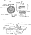
- Fig. 1 shows an example of the prior art.
- Fig. 2 shows an embodiment of the present invention, Fig. 2(a) being a sectional view and Fig. 2(b) being a plan view.
- Fig. 3 shows another embodiment of the present invention.
- Fig. 4 shows another embodiment of the present invention, Fig. 4(a) being a sectional view, and Fig. 4(b) being a plan view.
- Fig. 5 shows yet another embodiment of the present invention.
- Fig. 6 shows still another embodiment of the present invention.
- Fig. 7 shows yet another embodiment of the present invention.
- Fig. 2 shows a first embodiment of the linear-motion contactless power supply device of the present invention.
- secondary conductor 1 has a hollow-pipe structure having both ends connected to lead wires 2 and 3 through which induced voltage is taken out.
- Toroidal core 4 which is made of a high-frequency magnetic material, is affixed to secondary conductor 1 so as to completely cover this secondary conductor.
- Primary conductor 5 is arranged coaxial with the direction of linear movement within the hollow space of secondary conductor 1, primary conductor 5 and secondary conductor 1 being electrically isolated; and as necessary, a slidable support structure is provided between primary conductor 5 and secondary conductor 1.
- a slidable support structure is provided between primary conductor 5 and secondary conductor 1.
- employment of ceramic bearing structure 6 enables both electrical isolation and prevention of sagging in the direction of gravitational force due to the weight of primary conductor 5.
- Primary conductor 5 is stationary, both ends of primary conductor 5 are connected to high-frequency inverter 7, and a main magnetic flux is generated inside toroidal core 4 by high-frequency excitation.
- a single conductor of large current capacity is used as primary conductor 5, which can be operated at the limit of the current supply capacity of a high-frequency inverter.
- voltage is induced in secondary conductor 1 at a one-to-one turn ratio due to the construction of secondary conductor 1.
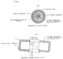
- Fig. 3 shows a contactless power supply system in which the contactless power supply device of the present invention shown in Fig. 2 is applied.
- movable unit 8 is constructed so as to slide on rail 9 , and secondary conductors and toroidal cores as shown in Fig. 2 are provided on both wing portions as viewed in the direction of motion.
- Primary conductor 5 is arranged in a loop pattern and passes through the hollow portion of the secondary conductors 1 on both wings.
- Both ends of secondary conductor 1 are connected to power transformer circuit 10 on movable unit 8 and, by means of a semiconductor switch provided within power transformer circuit 10, the output of secondary conductor 1 is converted to a low-frequency current or, following rectification, converted to direct current.
- the output of power transformer circuit 10 becomes the operating power source for electric load 11 such as an electric motor installed on movable unit 8.
- the primary conductor When the output current capacity of the high-frequency inverter is small, the primary conductor may be in the form of a multiple-wound coil as shown in Fig. 4. In this case, output voltage is generated on the secondary side at a ratio of N-to-1.
- a conductor having a hollow interior may be employed for the primary conductor and a fluid for cooling may be circulated through this space to prevent heat generation.
- Fig. 6 shows another embodiment of a linear-motion contactless power supply device according to the present invention.
- the primary coil is composed of a central litz wire bundle 31 and litz wire bundles divided into two portions 32 and 33 to the left and right of litz wire bundle 31.
- a litz wire bundle refers to a multitude of insulated wires, rather than being a single conductor, bundled and connected at both ends in order to prevent power loss that occurs due to skin effect during the passage of high-frequency current.
- the primary coil is formed by winding a single or multiple turns of this type of litz-wire wiring.
- the number of bundled wires for each of litz wire bundles 32 and 33 is set to one half the number of bundled wires of litz wire bundle 31, and electric current is caused to flow through each of these bundles that is half the current passing through litz wire bundle 31, thereby generating magnetic flux.
- a rod-shaped high-frequency magnetic substance 34 is connected in close contact over the entire length of linear motion, and this high-frequency magnetic substance 34 mechanically supports litz wire bundle 31.
- high-frequency magnetic substance core 36 forms a magnetic path for the main magnetic flux generated by the primary coil in a form that straddles high-frequency magnetic substance 34 over an extremely narrow interposed gap in order that the magnetic flux produced by the primary coil interlinks with secondary coil 35 to be described hereinbelow.
- High-frequency magnetic substance 34 and high-frequency magnetic substance core 36 are made of the same high-frequency magnetic material, and if their magnetic permeability is set to an extremely high level as compared with that of air (for example, 2000 times or greater), most of the magnetic flux generated by litz wire bundles 31, 32 and 33 making up the primary coil will interlink with secondary coil 35. Such a construction enables contactless power transfer from the primary to the secondary side with negligible loss.
- a non-magnetic support material 37 is connected in close contact along the entire length of linear sliding in the lower portions of litz wire bundles 32 and 33, and this support material mechanically supports these wire bundles.
- Fig. 7 shows a further development of the device of Fig. 6 in which litz wire bundles 31, 32 and 33 as well as high-frequency magnetic substance 34, which are non-moving components, are constituted as a single unit.
- mechanical strength can be ensured with no disruption of electromagnetic induction characteristics by inlaying the entire structure within base 37' of a non-magnetic material such as a ceramic.
- the gap between high-frequency magnetic substance 34 and high-frequency magnetic substance core 36 attached to the movable unit exerts a large and direct effect on power transfer efficiency.
- the stationary unit must therefore be machined so that this gap can be suppressed to an extremely small dimension, so that the size of this gap will not vary according to position, and so that aging will not occur.
- the mechanical precision of high-frequency magnetic core 36 and the rigidity of the positioning structure of the movable unit must attain high levels.
- the present invention is a device for transferring electric power from a stationary unit to a movable unit without direct contact and can be applied to industrial machinery such as machine tools.
Abstract
Description
- The present invention relates to a linear-motion contactless power supply system for transferring electrical power (including information based on electrical signals) in a linear direction without direct contact through the use of high-frequency electromagnetic induction.
- The device shown in Fig. 1 has been known as an example of linear-motion contactless power supply systems of the prior art. In this device, primary conductor (primary coil) 21 is strung as an aerial line, an
iron core 23 to which secondary conductor (secondary coil) 22 is attached surroundsprimary conductor 21 and is slidably disposed with respect toprimary conductor 21. In this case,primary conductor 21 is supported at bothend portions 24 in its longitudinal direction in order thatiron core 23 is permitted to slide (cf. Japanese Patent Publication No. 23723/1983). - However, if the device has a construction which is elongated in the direction of movement, the primary conductor produces a catenary line due to its own weight, and this leads to the possibility that the primary conductor will make contact with the movable core made of magnetic material on which the secondary conductor is wound in the vicinity of the center of the overall length of the primary conductor as a result of a long-term use or stress caused by mechanical vibration. As a result, support of the primary coil over the overall length of linear range by a non-magnetic rigid body has been considered, but such a structure tends to cause leakage of magnetic flux, and moreover, does not allow for a device of compact structure, and therefore has not proved to be practical. On the other hand, Japanese Patent Laid-open Hei 5-207603 discloses a device in which contactless power supply for a moving body moving on a road surface is constructed through the use of a litz wire bundle. However, such a device cannot be applied for apparatuses which are not intended to be installed on a road.
- The object of the present invention is to provide linear-motion contactless power supply device allowing a more compact construction and in which leakage of magnetic flux is prevented.
- Another object of the present invention is to provide a linear-motion contactless power supply device wherein the primary conductor (coil) is supported along its overall length by a non-magnetic body, and in which losses of power supply can be prevented without reducing the degree of electromagnetic coupling between the primary and secondary conductors (coils).
- A first linear-motion contactless power supply device according to the present invention is provided with a stationary unit and movable unit that can move along the longitudinal direction of this stationary unit, and supplies power from the stationary unit to the movable unit without direct contact, said power supply device being characterized in that the stationary unit is a cylindrical primary conductor to which is supplied a high-frequency alternating current, and that the movable unit is provided with a secondary conductor and a high-frequency toroidal core, wherein the secondary conductor is isolated from the primary conductor and is arranged coaxially with the primary conductor so as to be slidable in the longitudinal direction of the primary conductor, and the high-frequency toroidal core is arranged so as to cover the secondary conductor from the outside.
- A second linear-motion contactless power supply device according to the present invention is provided with a stationary unit and a movable unit that can move along the longitudinal direction of the stationary unit, and allows supply of electrical power from the stationary unit to the movable unit without direct contact, wherein the stationary unit includes a primary-side core, which is a rod-shaped high-frequency magnetic substance, and a primary-side coil made of litz wire bundles each of which is a multiplicity of insulated wires bundled and connected at both ends and to which a high-frequency alternating current is supplied, the primary core and the primary coil being fixed integrally by a non-magnetic material; and
the movable unit is made up of a high-frequency magnetic substance core arranged so as to straddle the litz wire bundle of the stationary unit and also of a secondary coil that is wound around this core. - As described above, the present invention offers an effect that a device can be realized in which leakage in magnetic flux interlinkage is unlikely to occur. In addition, the present invention provides a solution to the problem of mechanical support of the primary coil (or conductor) (i.e., sagging over the length of a structure due to the structure's own weight) in a linear-motion contactless power supply device, and furthermore, realizes a highly rigid structure that can stand up to long-term use and stress due to mechanical vibration.
- Fig. 1 shows an example of the prior art.
- Fig. 2 shows an embodiment of the present invention, Fig. 2(a) being a sectional view and Fig. 2(b) being a plan view.
- Fig. 3 shows another embodiment of the present invention.
- Fig. 4 shows another embodiment of the present invention, Fig. 4(a) being a sectional view, and Fig. 4(b) being a plan view.
- Fig. 5 shows yet another embodiment of the present invention.
- Fig. 6 shows still another embodiment of the present invention.
- Fig. 7 shows yet another embodiment of the present invention.
- Fig. 2 shows a first embodiment of the linear-motion contactless power supply device of the present invention.
- In the present embodiment,
secondary conductor 1 has a hollow-pipe structure having both ends connected tolead wires -
Toroidal core 4, which is made of a high-frequency magnetic material, is affixed tosecondary conductor 1 so as to completely cover this secondary conductor. -
Primary conductor 5 is arranged coaxial with the direction of linear movement within the hollow space ofsecondary conductor 1,primary conductor 5 andsecondary conductor 1 being electrically isolated; and as necessary, a slidable support structure is provided betweenprimary conductor 5 andsecondary conductor 1. As an example, employment of ceramic bearingstructure 6 enables both electrical isolation and prevention of sagging in the direction of gravitational force due to the weight ofprimary conductor 5. -
Primary conductor 5 is stationary, both ends ofprimary conductor 5 are connected to high-frequency inverter 7, and a main magnetic flux is generated insidetoroidal core 4 by high-frequency excitation. - In this device, a single conductor of large current capacity is used as
primary conductor 5, which can be operated at the limit of the current supply capacity of a high-frequency inverter. In this case, voltage is induced insecondary conductor 1 at a one-to-one turn ratio due to the construction ofsecondary conductor 1. - In the secondary conductor connected to the electric load, voltage is induced at both ends of the secondary conductor such that current flows to prevent changes in magnetic flux generated within
toroidal core 4 due to high-frequency excitation caused by current flowing throughprimary conductor 5. - Fig. 3 shows a contactless power supply system in which the contactless power supply device of the present invention shown in Fig. 2 is applied.
- In this system, the structure shown in Fig. 2 is serially connected in order to effectively use the main magnetic flux produced by the primary conductor. As a result, two sets of toroidal cores and secondary conductors are employed.
- Namely,
movable unit 8 is constructed so as to slide on rail 9 , and secondary conductors and toroidal cores as shown in Fig. 2 are provided on both wing portions as viewed in the direction of motion.Primary conductor 5 is arranged in a loop pattern and passes through the hollow portion of thesecondary conductors 1 on both wings. - Both ends of
secondary conductor 1 are connected topower transformer circuit 10 onmovable unit 8 and, by means of a semiconductor switch provided withinpower transformer circuit 10, the output ofsecondary conductor 1 is converted to a low-frequency current or, following rectification, converted to direct current. The output ofpower transformer circuit 10 becomes the operating power source forelectric load 11 such as an electric motor installed onmovable unit 8. - When the output current capacity of the high-frequency inverter is small, the primary conductor may be in the form of a multiple-wound coil as shown in Fig. 4. In this case, output voltage is generated on the secondary side at a ratio of N-to-1. In addition, as shown in Fig. 5, a conductor having a hollow interior may be employed for the primary conductor and a fluid for cooling may be circulated through this space to prevent heat generation.
- Fig. 6 shows another embodiment of a linear-motion contactless power supply device according to the present invention.
- In this device, the primary coil is composed of a central
litz wire bundle 31 and litz wire bundles divided into twoportions litz wire bundle 31. A litz wire bundle refers to a multitude of insulated wires, rather than being a single conductor, bundled and connected at both ends in order to prevent power loss that occurs due to skin effect during the passage of high-frequency current. - The primary coil is formed by winding a single or multiple turns of this type of litz-wire wiring. The number of bundled wires for each of
litz wire bundles litz wire bundle 31, and electric current is caused to flow through each of these bundles that is half the current passing throughlitz wire bundle 31, thereby generating magnetic flux. In the lower portion oflitz wire bundle 31, a rod-shaped high-frequencymagnetic substance 34 is connected in close contact over the entire length of linear motion, and this high-frequencymagnetic substance 34 mechanically supportslitz wire bundle 31. In addition, high-frequencymagnetic substance core 36 forms a magnetic path for the main magnetic flux generated by the primary coil in a form that straddles high-frequencymagnetic substance 34 over an extremely narrow interposed gap in order that the magnetic flux produced by the primary coil interlinks withsecondary coil 35 to be described hereinbelow. - High-frequency
magnetic substance 34 and high-frequencymagnetic substance core 36 are made of the same high-frequency magnetic material, and if their magnetic permeability is set to an extremely high level as compared with that of air (for example, 2000 times or greater), most of the magnetic flux generated bylitz wire bundles secondary coil 35. Such a construction enables contactless power transfer from the primary to the secondary side with negligible loss. - In addition, a
non-magnetic support material 37 is connected in close contact along the entire length of linear sliding in the lower portions oflitz wire bundles - The primary coil is thus mechanically supported over its entire length. Fig. 7 shows a further development of the device of Fig. 6 in which
litz wire bundles magnetic substance 34, which are non-moving components, are constituted as a single unit. In the embodiment of Fig. 7, mechanical strength can be ensured with no disruption of electromagnetic induction characteristics by inlaying the entire structure within base 37' of a non-magnetic material such as a ceramic. In this construction, however, the gap between high-frequencymagnetic substance 34 and high-frequencymagnetic substance core 36 attached to the movable unit exerts a large and direct effect on power transfer efficiency. The stationary unit must therefore be machined so that this gap can be suppressed to an extremely small dimension, so that the size of this gap will not vary according to position, and so that aging will not occur. Obviously, the mechanical precision of high-frequencymagnetic core 36 and the rigidity of the positioning structure of the movable unit must attain high levels. - The present invention is a device for transferring electric power from a stationary unit to a movable unit without direct contact and can be applied to industrial machinery such as machine tools.
Claims (4)
- A linear-motion contactless power supply device including a stationary unit and a movable unit movable along the longitudinal direction of said stationary unit for supplying electrical power from said stationary unit to said movable unit without direct contact;
said stationary unit being a cylindrical primary conductor to which a high-frequency alternating current is supplied;
said movable unit being provided with a secondary conductor which is isolated from said primary conductor and which is arranged coaxially with said primary conductor so as to be slidable in the longitudinal direction of and with respect to said primary conductor and also provided with a high-frequency toroidal core which is arranged so as to cover said secondary conductor from the outside. - A linear-motion contactless power supply device according to claim 1 wherein said secondary conductor having said toroidal core on the outside is provided on both wing portions of a movable unit, and a primary conductor is arranged in a oblong loop form that passes through hollow portions of these secondary conductors.
- A linear-motion contactless power supply device including a stationary unit and a movable unit movable along the longitudinal direction of said stationary unit for supplying electrical power from said stationary unit to said movable unit without direct contact;
said stationary unit comprising a primary core of a rod-shaped high-frequency magnetic substance, and a primary coil made up of litz wire bundles each of which is a multiplicity of insulated wires bundled and connected at both ends and to which a high-frequency alternating current is supplied, said primary core and said primary-side coil being fixed as a single unit by a non-magnetic material; and
said movable unit comprising a high-frequency magnetic substance core arranged so as to straddle said litz wire bundle of said stationary unit and a secondary coil that is wound around this core. - A linear-motion contactless power supply device according to claim 3 wherein said non-magnetic material is a ceramic.
Applications Claiming Priority (7)
| Application Number | Priority Date | Filing Date | Title |
|---|---|---|---|
| JP47856/94 | 1994-02-21 | ||
| JP4785694 | 1994-02-21 | ||
| JP4785694 | 1994-02-21 | ||
| JP5322894 | 1994-02-24 | ||
| JP53228/94 | 1994-02-24 | ||
| JP5322894 | 1994-02-24 | ||
| PCT/JP1995/000225 WO1995022849A1 (en) | 1994-02-21 | 1995-02-17 | Direct-acting non-contact feeder |
Publications (3)
| Publication Number | Publication Date |
|---|---|
| EP0748024A1 true EP0748024A1 (en) | 1996-12-11 |
| EP0748024A4 EP0748024A4 (en) | 1997-04-16 |
| EP0748024B1 EP0748024B1 (en) | 1999-09-15 |
Family
ID=26388061
Family Applications (1)
| Application Number | Title | Priority Date | Filing Date |
|---|---|---|---|
| EP95909105A Expired - Lifetime EP0748024B1 (en) | 1994-02-21 | 1995-02-17 | Direct-acting non-contact feeder |
Country Status (6)
| Country | Link |
|---|---|
| US (1) | US5737211A (en) |
| EP (1) | EP0748024B1 (en) |
| JP (1) | JP3295938B2 (en) |
| KR (1) | KR100372174B1 (en) |
| DE (1) | DE69512217T2 (en) |
| WO (1) | WO1995022849A1 (en) |
Cited By (2)
| Publication number | Priority date | Publication date | Assignee | Title |
|---|---|---|---|---|
| WO2001095349A3 (en) * | 2000-06-08 | 2002-03-21 | Ronald Kevin Fricker | Lighting assembly |
| WO2010046744A2 (en) | 2008-10-20 | 2010-04-29 | Toyota Jidosha Kabushiki Kaisha | Power supply system |
Families Citing this family (33)
| Publication number | Priority date | Publication date | Assignee | Title |
|---|---|---|---|---|
| WO1999008359A1 (en) * | 1997-08-08 | 1999-02-18 | Meins Jurgen G | Method and apparatus for supplying contactless power |
| US6233834B1 (en) * | 1998-02-24 | 2001-05-22 | Milli Sensor Systems & Actuators | Miniature transformers for millimachined instruments |
| US6683522B2 (en) * | 1999-02-24 | 2004-01-27 | Milli Sensor Systems & Actuators, Inc. | Planar miniature inductors and transformers |
| US7126450B2 (en) | 1999-06-21 | 2006-10-24 | Access Business Group International Llc | Inductively powered apparatus |
| JP2002134340A (en) * | 2000-10-20 | 2002-05-10 | Shinko Electric Co Ltd | Non-contact power supply transformer |
| US6307766B1 (en) | 2000-11-22 | 2001-10-23 | Bayside Controls, Inc. | Contactless power system |
| WO2002095775A1 (en) * | 2001-05-21 | 2002-11-28 | Milli Sensor Systems & Actuators, Inc. | Planar miniature inductors and transformers and miniature transformers for millimachined instruments |
| US20050023098A1 (en) * | 2003-07-01 | 2005-02-03 | Imad Mahawili | Energy recovery system |
| US6900621B1 (en) * | 2003-07-03 | 2005-05-31 | Inovys | Digitally controlled modular power supply for automated test equipment |
| US7573000B2 (en) * | 2003-07-11 | 2009-08-11 | Lincoln Global, Inc. | Power source for plasma device |
| US6998573B2 (en) * | 2003-07-11 | 2006-02-14 | Lincoln Global, Inc. | Transformer module for a welder |
| US7274000B2 (en) * | 2003-07-11 | 2007-09-25 | Lincoln Global, Inc. | Power source for high current welding |
| JP4478470B2 (en) * | 2004-01-26 | 2010-06-09 | キヤノン株式会社 | Positioning stage device |
| US7376961B2 (en) * | 2004-05-28 | 2008-05-20 | International Business Machines Corporation | Contactless power and/or data transmission in an automated data storage library employing segmented coils |
| US20090057084A1 (en) * | 2004-06-30 | 2009-03-05 | Energy Recovery Technology, Llc | Energy recovery system |
| US20070289793A1 (en) * | 2006-06-16 | 2007-12-20 | Imad Mahawili | Energy recovery system |
| US20090179430A1 (en) * | 2006-06-16 | 2009-07-16 | Energy Recovery Technology, Inc. | Energy recovery system |
| US20080088399A1 (en) * | 2006-09-27 | 2008-04-17 | Mayo Michael J | Series impedance matched inductive power pick up |
| US20090038902A1 (en) * | 2007-08-07 | 2009-02-12 | Sitaramarao Srinivas Yechuri | Method of providing electricity to a moving automobile |
| US20090153099A1 (en) * | 2007-12-17 | 2009-06-18 | Energy Recovery Technology, Llc | Method of electric energy transfer between a vehicle and a stationary collector |
| WO2010036914A2 (en) * | 2008-09-25 | 2010-04-01 | Energy Recovery Technology, Llc. | Vehicle energy recovery system |
| DE102009003846A1 (en) * | 2009-04-29 | 2010-11-04 | Weidmüller Interface GmbH & Co. KG | System for the contactless energy and data supply of bus subscriber modules |
| JP2012216687A (en) * | 2011-03-31 | 2012-11-08 | Sony Corp | Power reception coil, power reception device, and non contact power transmission system |
| TWM446403U (en) * | 2012-07-25 | 2013-02-01 | Phihong Technology Co Ltd | Non-contact transformer |
| KR102588559B1 (en) | 2015-02-06 | 2023-10-12 | 퍼시몬 테크놀로지스 코포레이션 | Mobile power coupling and robot with mobile power coupling |
| EP3188198A1 (en) * | 2015-12-31 | 2017-07-05 | Schneeberger Holding AG | Device for contactless transmission of electric energy into a moving system of a sliding device |
| CN107276238B (en) * | 2016-04-08 | 2020-12-22 | 泰科电子(上海)有限公司 | Wireless power supply device and electrical equipment |
| US10483895B2 (en) * | 2017-08-25 | 2019-11-19 | Rockwell Automation Technologies, Inc. | Method and apparatus for wireless power transfer to an independent moving cart |
| US11539244B2 (en) | 2017-09-28 | 2022-12-27 | Rockwell Automation Technologies, Inc. | Method and apparatus for data transmission over an inductive link for an independent cart system |
| US10608469B2 (en) | 2017-09-28 | 2020-03-31 | Rockwell Automation Technologies, Inc. | Method and apparatus for power transfer to an independent moving cart during travel along a track |
| US11142082B2 (en) * | 2019-08-07 | 2021-10-12 | Hiwin Technologies Corp. | Linear transmission device with capability of wireless power supply |
| US10985685B1 (en) | 2019-09-30 | 2021-04-20 | Rockwell Automation Technologies, Inc. | System and method for wireless power transfer in a linear cart system |
| EP4110644A1 (en) * | 2020-02-27 | 2023-01-04 | MOTX Ltd. | Contactless electrical power transfer and motive device therewith |
Citations (3)
| Publication number | Priority date | Publication date | Assignee | Title |
|---|---|---|---|---|
| WO1992017929A1 (en) * | 1991-03-26 | 1992-10-15 | Piper, James, William | Inductive power distribution system |
| WO1993023909A1 (en) * | 1992-05-10 | 1993-11-25 | Auckland Uniservices Limited | A primary inductive pathway |
| US5301096A (en) * | 1991-09-27 | 1994-04-05 | Electric Power Research Institute | Submersible contactless power delivery system |
Family Cites Families (13)
| Publication number | Priority date | Publication date | Assignee | Title |
|---|---|---|---|---|
| JPS53124813A (en) * | 1977-04-06 | 1978-10-31 | Mitsui Eng & Shipbuild Co Ltd | Non-contact current collecting apparatus |
| JPS589571B2 (en) * | 1980-04-04 | 1983-02-22 | 工業技術院長 | Contactless power supply device |
| JPS5823723B2 (en) * | 1980-04-04 | 1983-05-17 | 工業技術院長 | Contactless power supply device |
| KR960007847B1 (en) * | 1986-10-16 | 1996-06-12 | 선드 스트랜드 데이타 콘트롤 인코포레이티드 | Inductive coupled power system |
| JPH04156242A (en) * | 1990-10-17 | 1992-05-28 | Sekisui Chem Co Ltd | Wireless power supply system |
| US5341280A (en) * | 1991-09-27 | 1994-08-23 | Electric Power Research Institute | Contactless coaxial winding transformer power transfer system |
| JPH05207603A (en) * | 1992-01-24 | 1993-08-13 | Daifuku Co Ltd | Noncontact power supply for moving object |
| JPH0614479A (en) * | 1992-06-26 | 1994-01-21 | Daifuku Co Ltd | Non-contact feeding mat |
| JPH0670491A (en) * | 1992-08-12 | 1994-03-11 | Tokyo Gas Co Ltd | Power supply for movable explosion-proof apparatus |
| JP2747402B2 (en) * | 1992-10-30 | 1998-05-06 | 三菱電機株式会社 | Transmission line monitoring sensor |
| JP3085491B2 (en) * | 1992-12-25 | 2000-09-11 | 株式会社安川電機 | Wireless power supply |
| JPH0787691A (en) * | 1993-09-14 | 1995-03-31 | Matsushita Electric Works Ltd | Non-connected feeder system |
| US5608615A (en) * | 1996-03-11 | 1997-03-04 | Luce; John W. | Asynchronous intergrid transfer apparatus |
-
1995
- 1995-02-17 EP EP95909105A patent/EP0748024B1/en not_active Expired - Lifetime
- 1995-02-17 US US08/693,251 patent/US5737211A/en not_active Expired - Fee Related
- 1995-02-17 JP JP50859395A patent/JP3295938B2/en not_active Expired - Fee Related
- 1995-02-17 KR KR1019960704563A patent/KR100372174B1/en not_active IP Right Cessation
- 1995-02-17 DE DE69512217T patent/DE69512217T2/en not_active Expired - Fee Related
- 1995-02-17 WO PCT/JP1995/000225 patent/WO1995022849A1/en active IP Right Grant
Patent Citations (3)
| Publication number | Priority date | Publication date | Assignee | Title |
|---|---|---|---|---|
| WO1992017929A1 (en) * | 1991-03-26 | 1992-10-15 | Piper, James, William | Inductive power distribution system |
| US5301096A (en) * | 1991-09-27 | 1994-04-05 | Electric Power Research Institute | Submersible contactless power delivery system |
| WO1993023909A1 (en) * | 1992-05-10 | 1993-11-25 | Auckland Uniservices Limited | A primary inductive pathway |
Non-Patent Citations (1)
| Title |
|---|
| See also references of WO9522849A1 * |
Cited By (4)
| Publication number | Priority date | Publication date | Assignee | Title |
|---|---|---|---|---|
| WO2001095349A3 (en) * | 2000-06-08 | 2002-03-21 | Ronald Kevin Fricker | Lighting assembly |
| WO2010046744A2 (en) | 2008-10-20 | 2010-04-29 | Toyota Jidosha Kabushiki Kaisha | Power supply system |
| WO2010046744A3 (en) * | 2008-10-20 | 2010-06-17 | Toyota Jidosha Kabushiki Kaisha | Inductive power supply system with overlapping coils |
| US8482161B2 (en) | 2008-10-20 | 2013-07-09 | Toyota Jidosha Kabushiki Kaisha | Inductive power supply system with overlapping coils |
Also Published As
| Publication number | Publication date |
|---|---|
| US5737211A (en) | 1998-04-07 |
| WO1995022849A1 (en) | 1995-08-24 |
| DE69512217T2 (en) | 1999-12-30 |
| EP0748024A4 (en) | 1997-04-16 |
| DE69512217D1 (en) | 1999-10-21 |
| KR100372174B1 (en) | 2003-04-11 |
| JP3295938B2 (en) | 2002-06-24 |
| EP0748024B1 (en) | 1999-09-15 |
Similar Documents
| Publication | Publication Date | Title |
|---|---|---|
| EP0748024B1 (en) | Direct-acting non-contact feeder | |
| US6005304A (en) | Arrangement for contactless inductive transmission of electrical power | |
| US7969045B2 (en) | Installation | |
| KR100392308B1 (en) | An integrated apparatus of permanent magnet excited synchronous motor and non-contact power feed device | |
| KR20170080497A (en) | Device for the Contact-Free Transfer of Electrical Energy into a Moving System of a Shifting Device | |
| JPS6143947B2 (en) | ||
| JP2008539584A (en) | Inductively coupled power transfer system | |
| JP6726159B2 (en) | Mobile power coupling and robot with mobile power coupling | |
| DE502004008696D1 (en) | ARRANGEMENT FOR CONTACTLESS INDUCTIVE TRANSMISSION OF ELECTRICAL POWER | |
| JPH07322535A (en) | Noncontact power supply for direct motion mechanism | |
| KR101172592B1 (en) | Power receiving module for non-contact power supply apparatus | |
| US9473211B2 (en) | Device for the inductive transmission of electrical energy | |
| JP2003087902A (en) | Inductive feeding device and truck mounting the same thereon | |
| EP3572846B1 (en) | High power transformer and transmitter for geophysical measurements | |
| JP2005261200A (en) | Contactless power feeding apparatus | |
| EP0200313A1 (en) | Forceless non-contacting power transformer | |
| US7911307B2 (en) | Rotary transformer | |
| SU1714700A1 (en) | Biased three-phase transformer | |
| KR100453776B1 (en) | Transformers | |
| CN110612583B (en) | Connection structure of coil unit | |
| SE9703561D0 (en) | Magnetic winding coupler | |
| EP0555560A1 (en) | Low leakage transformer | |
| JPH10270273A (en) | Different loading system detachable type electric power supplying method | |
| SU860154A1 (en) | Welding transformer | |
| US20060214516A1 (en) | 2-Dimensional displacement device |
Legal Events
| Date | Code | Title | Description |
|---|---|---|---|
| PUAI | Public reference made under article 153(3) epc to a published international application that has entered the european phase |
Free format text: ORIGINAL CODE: 0009012 |
|
| 17P | Request for examination filed |
Effective date: 19960828 |
|
| AK | Designated contracting states |
Kind code of ref document: A1 Designated state(s): DE GB SE |
|
| A4 | Supplementary search report drawn up and despatched | ||
| AK | Designated contracting states |
Kind code of ref document: A4 Designated state(s): DE GB SE |
|
| 17Q | First examination report despatched |
Effective date: 19980326 |
|
| GRAG | Despatch of communication of intention to grant |
Free format text: ORIGINAL CODE: EPIDOS AGRA |
|
| GRAG | Despatch of communication of intention to grant |
Free format text: ORIGINAL CODE: EPIDOS AGRA |
|
| GRAH | Despatch of communication of intention to grant a patent |
Free format text: ORIGINAL CODE: EPIDOS IGRA |
|
| GRAH | Despatch of communication of intention to grant a patent |
Free format text: ORIGINAL CODE: EPIDOS IGRA |
|
| GRAA | (expected) grant |
Free format text: ORIGINAL CODE: 0009210 |
|
| AK | Designated contracting states |
Kind code of ref document: B1 Designated state(s): DE GB SE |
|
| PG25 | Lapsed in a contracting state [announced via postgrant information from national office to epo] |
Ref country code: SE Free format text: THE PATENT HAS BEEN ANNULLED BY A DECISION OF A NATIONAL AUTHORITY Effective date: 19990915 |
|
| REF | Corresponds to: |
Ref document number: 69512217 Country of ref document: DE Date of ref document: 19991021 |
|
| PLBE | No opposition filed within time limit |
Free format text: ORIGINAL CODE: 0009261 |
|
| STAA | Information on the status of an ep patent application or granted ep patent |
Free format text: STATUS: NO OPPOSITION FILED WITHIN TIME LIMIT |
|
| 26N | No opposition filed | ||
| REG | Reference to a national code |
Ref country code: GB Ref legal event code: IF02 |
|
| PGFP | Annual fee paid to national office [announced via postgrant information from national office to epo] |
Ref country code: GB Payment date: 20020220 Year of fee payment: 8 |
|
| PGFP | Annual fee paid to national office [announced via postgrant information from national office to epo] |
Ref country code: DE Payment date: 20020306 Year of fee payment: 8 |
|
| PG25 | Lapsed in a contracting state [announced via postgrant information from national office to epo] |
Ref country code: GB Free format text: LAPSE BECAUSE OF NON-PAYMENT OF DUE FEES Effective date: 20030217 |
|
| PG25 | Lapsed in a contracting state [announced via postgrant information from national office to epo] |
Ref country code: DE Free format text: LAPSE BECAUSE OF NON-PAYMENT OF DUE FEES Effective date: 20030902 |
|
| GBPC | Gb: european patent ceased through non-payment of renewal fee |