EP0747902A2 - Tape cassette loading mechanism in magnetic recording/reproducing apparatus - Google Patents
Tape cassette loading mechanism in magnetic recording/reproducing apparatus Download PDFInfo
- Publication number
- EP0747902A2 EP0747902A2 EP96303534A EP96303534A EP0747902A2 EP 0747902 A2 EP0747902 A2 EP 0747902A2 EP 96303534 A EP96303534 A EP 96303534A EP 96303534 A EP96303534 A EP 96303534A EP 0747902 A2 EP0747902 A2 EP 0747902A2
- Authority
- EP
- European Patent Office
- Prior art keywords
- tape cassette
- pins
- deck
- reproducing apparatus
- magnetic recording
- Prior art date
- Legal status (The legal status is an assumption and is not a legal conclusion. Google has not performed a legal analysis and makes no representation as to the accuracy of the status listed.)
- Granted
Links
Images

Classifications
-
- G—PHYSICS
- G11—INFORMATION STORAGE
- G11B—INFORMATION STORAGE BASED ON RELATIVE MOVEMENT BETWEEN RECORD CARRIER AND TRANSDUCER
- G11B25/00—Apparatus characterised by the shape of record carrier employed but not specific to the method of recording or reproducing, e.g. dictating apparatus; Combinations of such apparatus
- G11B25/06—Apparatus characterised by the shape of record carrier employed but not specific to the method of recording or reproducing, e.g. dictating apparatus; Combinations of such apparatus using web-form record carriers, e.g. tape
- G11B25/066—Apparatus characterised by the shape of record carrier employed but not specific to the method of recording or reproducing, e.g. dictating apparatus; Combinations of such apparatus using web-form record carriers, e.g. tape adapted for use with containers of different sizes or configurations; adaptor devices therefor
-
- G—PHYSICS
- G11—INFORMATION STORAGE
- G11B—INFORMATION STORAGE BASED ON RELATIVE MOVEMENT BETWEEN RECORD CARRIER AND TRANSDUCER
- G11B15/00—Driving, starting or stopping record carriers of filamentary or web form; Driving both such record carriers and heads; Guiding such record carriers or containers therefor; Control thereof; Control of operating function
- G11B15/60—Guiding record carrier
-
- G—PHYSICS
- G11—INFORMATION STORAGE
- G11B—INFORMATION STORAGE BASED ON RELATIVE MOVEMENT BETWEEN RECORD CARRIER AND TRANSDUCER
- G11B15/00—Driving, starting or stopping record carriers of filamentary or web form; Driving both such record carriers and heads; Guiding such record carriers or containers therefor; Control thereof; Control of operating function
- G11B15/18—Driving; Starting; Stopping; Arrangements for control or regulation thereof
- G11B15/26—Driving record carriers by members acting directly or indirectly thereon
- G11B15/32—Driving record carriers by members acting directly or indirectly thereon through the reels or cores on to which the record carrier is wound
Definitions
- the present invention relates to a tape cassette loading mechanism in a magnetic recording/reproducing apparatus such as a VCR, a CAMCORDER, and a digital-video cassette recorder (D-VCR), and more particularly, to a tape cassette loading mechanism in a magnetic recording/reproducing apparatus which moves reel tables so that at least different-sized tape cassettes are selectively and stably loaded on the different-sized reel tables.
- a magnetic recording/reproducing apparatus such as a VCR, a CAMCORDER, and a digital-video cassette recorder (D-VCR)
- D-VCR digital-video cassette recorder
- a loading pin for supporting a tape cassette to be stably loaded on a reel table is installed in a deck mechanism in a magnetic recording/reproducing apparatus such as a VCR, a CAMCORDER, and a digital-video cassette recorder (D-VCR).
- a magnetic recording/reproducing apparatus such as a VCR, a CAMCORDER, and a digital-video cassette recorder (D-VCR).
- the present invention is contrived in accordance with the above requirement, and it is an aim of embodiments of the present invention to provide a tape cassette loading mechanism in a magnetic recording/reproducing apparatus, which supports tape cassettes so that different-sized tape cassettes can be safely and selectively seated on reel tables.
- a tape cassette loading mechanism in a magnetic recording/reproducing apparatus comprising: a first deck having first and second arc-shaped holes and first and second fixed pins are formed therein, wherein the holes and pins, respectively, are separated by a predetermined distance therebetween; and a second deck having third and fourth arc-shaped holes corresponding to the first and second holes formed therein which includes: a head drum having a magnetic head and a guiding device for guiding a magnetic tape is installed; a pair of rotating arms rotatably installed on the first and second fixed pins, respectively, for supporting reel tables on which different-sized tape cassettes are selectively loaded; a pair of driving arms rotatably combined with the first and second fixed pins each having gear portions that are engaged to one another; a driving motor connected to one of the gear portions of the driving arms; connecting means for connecting the driving arms and rotating arms to transmit the power from the driving motor to the respective rotating arms; and supporting means for supporting different-sized tape cassettes loaded on the
- motors for rotating the respective reel tables are installed on each of the rotating arms, respectively.
- the connecting means preferably includes: cavities respectively formed on the bottom of the driving arms; indented portions formed on the top portions of the rotating arms corresponding to the cavities; and coil springs disposed between the cavities and the indented portions, respectively.
- the device further comprises preventing means for preventing excess rotation of said rotating arms.
- Said preventing means may include: protrusions formed on said rotating arms respectively; and stoppers formed on said first deck.
- the supporting means preferably includes first and second loading pins fixed on the rotating arms, respectively, and third and fourth loading pins respectively on sides of the second deck such that the first and second and third and fourth loading pins support different-sized tape cassettes, respectively.
- the first and second loading pins are preferably rotated with the rotating arms and support a small tape cassette, and the third and fourth loading pins are fixed on the upper deck and support a large tape cassette.
- auxiliary loading pins for supporting the front portion of a tape cassette may further be provided on the upper deck.
- the first deck is a lower deck and the second deck is an upper deck.
- first and second arc-shaped holes 200a and 200b are formed on a first, lower, deck 200, and first and second fixed pins 218 and 228 separated from each other by a predetermined distance are fixedly installed between the holes 200a and 200b.
- a second, upper, deck 100 is installed above the lower deck 200 such that the two decks are separated from each other by a predetermined distance.
- rotating arms 211 and 221 are rotatably coupled to the first and second fixed pins 218 and 228 on the lower deck 200.
- Driving arms 212 and 222 each having geared portions 212a and 222a are also rotatably coupled to the first and second fixed pins 218 and 228 wherein the geared portions 212a and 222a are engaged with each other.
- the driving arms 212 and 222 are elastically biased toward the rotating arms 211 and 221, respectively, via springs 219a and 229a and washers 219b and 229b.
- a driving motor 230 for generating a driving force is installed at one side of the lower deck 200.
- the driving force is transmitted to the gear portion 222a from the driving motor 230 via a gear train 232.
- a connecting means for connecting the driving arms 212 and 222 and the rotating arms 211 and 221 is provided so that the power of the driving motor 230 can be transmitted to the respective rotating arms 211 and 221.
- the connecting means includes: cavities 212b and 222b formed on the respective lower surfaces of the driving arms 212 and 222; indented portions 211c and 221c formed on the respective rotating arms 211 and 221 corresponding to the cavities 212b and 222b; and coil springs 213 and 223 disposed between the cavities 212b and 222b and indented portions 211c and 221c, respectively. That is, the coil springs 213 and 223 are disposed halfway in cavities 212b and 222b, respectively, and halfway in indented portions 211c and 221c, respectively.
- the driving motor 230 transmits power to the rotating arms 211 and 221 via the coil springs 213 and 223.
- reel tables 210 and 220 and motors 216 and 226 for rotation thereof are installed on rotating arms 211 and 221, respectively.
- coupling holes 211b and 221b to which the motors 216 and 226 are coupled are formed on each rotating arm 211 and 221.
- Plates 215 and 225 having holes 215a and 225a are fixedly installed at the rotating arms 211 and 221, being supported above the coupling holes 211b and 221b by a plurality of supports 214 and 224.
- the rotors of motors 216 and 226 connect tightly to the reel tables 210 and 220 through the holes 214a and 225a of the plates 215 and 225.
- preventing means for preventing the excess rotation of the rotating arms 211 and 221 is further provided constituted by protrusions 211a and 221a formed at the outer ends of the rotating arms 211 and 221, and stoppers 217a, 217b, 227a and 227b formed on the lower deck 200 for limiting the rotation of the rotating arms 211 and 221.
- the stoppers 217a, 217b, 227a and 227b can be formed at predetermined positions along the rotating course of the protrusions 211a and 221a.
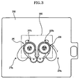
- the supporting means includes first and second loading pins 201 and 202 fixed on the plates 215 and 225, respectively, and third and fourth loading pins 106 and 107 are fixed at the sides on the upper deck 100 such that the first and second loading pins 201 and 202 and third and fourth loading pins 106 and 107 selectively support different-sized tape cassettes. That is, as shown in Figures 3 and 4, the first and second loading pins 201 and 202 support from the bottom the back end of a small tape cassette 300 seated on the reel tables 210 and 220. At this time, the third and fourth loading pins 106 and 107 do not interfere with the small tape cassette 300.
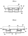
- Figures 5 and 6 show the third and fourth loading pins 106 and 107 supporting the lower edge portions of a large tape cassette 400.
- the first and second loading pins 201 and 202 are positioned at the reel portion.
- a clearance 404 is formed between the cassette 400 and first and second loading pins 201 and 202 so that the pins 201 and 202 do not interfere with the large tape cassette 400.
- the first and second loading pins 201 and 202 can be formed so that the first and second loading pins 201 and 202 support the large tape cassette 400 in addition to the third and fourth loading pins 106 and 107.
- auxiliary loading pins 108 and 109 are installed on the upper deck 100 to further the front portion of the small tape cassette 300 from the bottom thereof.
- the reel tables 210 and 220 and the first and second loading pins 201 and 202 pass through the third and fourth holes 100a and 100b to the upper deck 100.
- the tape cassette loading mechanism according to the present invention having such a configuration has the following functional effects.
- the distance between the reel tables 210 and 220 is controlled as follows. First, when the driving motor 230 is driven so that the last gear of gear train 232 engaged with the gear portion 222a of the driving arm 222 rotates counterclockwise, the two engaged rotating arms 211 and 221 rotate along the direction of arrow X of the third and fourth holes 100a and 100b. At this time, the protrusions 211a and 221a of the rotating arms 211 and 221 contact the stoppers 217a and 227a. The driving arms 212 and 222 are rotated slightly further as the driving arms 212 and 222 press against the coil springs 213 and 223 by the power of the driving motor 230.
- the reel tables 210 and 220 are stably at rest at their final position.
- the large tape cassette 400 as shown in Figures 5 and 6, is stably supported by the third and fourth loading pins 106 and 107.
- the first and second loading pins 201 and 202 are positioned under the tape cassette 400 having a clearance therefrom to thereby not interfere during loading of the tape cassette 400 on the reel tables 210 and 220.
- the distance between the reel tables 210 and 220 is controlled as follows.
- the driving motor 230 is driven so that the final gear of the gear train 232 which is engaged with the gear portion 222a of the driving arm 222 rotates clockwise, the two engaged rotating arms 211 and 221 rotate in the direction of arrow Y along the third and fourth holes 100a and 100b.
- the protrusions 211a and 221a of the rotating arms 211 and 221 make contact with the stoppers 217b and 227b.
- the driving arms 212 and 222 are further rotated by the power of the driving motor 230 depressing the coil springs 213 and 223.
- the rotating arms 211 and 221 adhere closely to the respective stoppers 217b and 227b due to the restoring force of the springs 213 and 223.
- the reel tables 210 and 220 are stably at rest at their final position.
- the small tape cassette can be seated on the two reel tables 210 and 220 which are separated by a small distance therebetween.
- the first and second loading pins 201 and 202 support the small tape cassette 300 loaded on the reel tables 210 and 220 from the bottom, and the first and second loading pins 201 and 202 support the head portion.
- the third and fourth loading pins 106 and 107 do not interfere with the small tape cassette 300.
- the different-sized tape cassettes 300 and 400 can be loaded onto the reel tables 210 and 220 and stably supported selectively by the first and second loading pins 201 and 202 moving with the reel tables 210 and 220, and the third and fourth loading pins 106 and 107 fixed onto the upper deck 100.
Landscapes
- Automatic Tape Cassette Changers (AREA)
- Replacement Of Web Rolls (AREA)
- Casings For Electric Apparatus (AREA)
- Transmission Devices (AREA)
Abstract
Description
- The present invention relates to a tape cassette loading mechanism in a magnetic recording/reproducing apparatus such as a VCR, a CAMCORDER, and a digital-video cassette recorder (D-VCR), and more particularly, to a tape cassette loading mechanism in a magnetic recording/reproducing apparatus which moves reel tables so that at least different-sized tape cassettes are selectively and stably loaded on the different-sized reel tables.
- Generally, a loading pin for supporting a tape cassette to be stably loaded on a reel table is installed in a deck mechanism in a magnetic recording/reproducing apparatus such as a VCR, a CAMCORDER, and a digital-video cassette recorder (D-VCR).
- Meanwhile, a mechanism has recently been proposed whereby a reel table is moved so that different-sized tape cassettes are selectively used. This mechanism which can selectively load different-sized tape cassettes requires supporting means for stably and selectively supporting the different-sized tape cassettes.
- The present invention is contrived in accordance with the above requirement, and it is an aim of embodiments of the present invention to provide a tape cassette loading mechanism in a magnetic recording/reproducing apparatus, which supports tape cassettes so that different-sized tape cassettes can be safely and selectively seated on reel tables.
- According to a first aspect of the present invention, there is provided a tape cassette loading mechanism in a magnetic recording/reproducing apparatus, comprising: a first deck having first and second arc-shaped holes and first and second fixed pins are formed therein, wherein the holes and pins, respectively, are separated by a predetermined distance therebetween; and a second deck having third and fourth arc-shaped holes corresponding to the first and second holes formed therein which includes: a head drum having a magnetic head and a guiding device for guiding a magnetic tape is installed; a pair of rotating arms rotatably installed on the first and second fixed pins, respectively, for supporting reel tables on which different-sized tape cassettes are selectively loaded; a pair of driving arms rotatably combined with the first and second fixed pins each having gear portions that are engaged to one another; a driving motor connected to one of the gear portions of the driving arms; connecting means for connecting the driving arms and rotating arms to transmit the power from the driving motor to the respective rotating arms; and supporting means for supporting different-sized tape cassettes loaded on the reel tables.
- Here, it is preferable that motors for rotating the respective reel tables are installed on each of the rotating arms, respectively.
- The connecting means preferably includes: cavities respectively formed on the bottom of the driving arms; indented portions formed on the top portions of the rotating arms corresponding to the cavities; and coil springs disposed between the cavities and the indented portions, respectively.
- Preferably, the device further comprises preventing means for preventing excess rotation of said rotating arms. Said preventing means may include: protrusions formed on said rotating arms respectively; and stoppers formed on said first deck.
- The supporting means preferably includes first and second loading pins fixed on the rotating arms, respectively, and third and fourth loading pins respectively on sides of the second deck such that the first and second and third and fourth loading pins support different-sized tape cassettes, respectively.
- The first and second loading pins are preferably rotated with the rotating arms and support a small tape cassette, and the third and fourth loading pins are fixed on the upper deck and support a large tape cassette.
- Also, auxiliary loading pins for supporting the front portion of a tape cassette may further be provided on the upper deck.
- Preferably, the first deck is a lower deck and the second deck is an upper deck.
- For a better understanding of the invention, and to show how embodiments of the same may be carried into effect, reference will now be made, by way of example, to the accompanying diagrammatic drawings, in which:
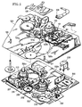
- Figure 1 is a schematic perspective view showing a tape cassette loading mechanism according to an embodiment of the present invention;
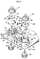
- Figure 2 is an exploded perspective view showing the essential parts of Figure 1 extracted;
- Figure 3 is a plan view showing the state of the apparatus with a small tape cassette loaded;
- Figure 4 is a schematic sectional side view of Figure 3;
- Figure 5 is a plan view showing the state of the apparatus with a large tape cassette loaded; and
- Figure 6 is a schematic sectional side view of Figure 5.
- A preferred embodiment according to the present invention will be described in detail with reference to the attached drawings.
- Referring to Figures 1 and 2, first and second arc-
shaped holes deck 200, and first and second fixedpins holes deck 100 is installed above thelower deck 200 such that the two decks are separated from each other by a predetermined distance. - A
head drum 120 and predetermined guide devices for guiding a tape (not shown) are installed on theupper deck 100. The guide devices includeguide rollers pinch roller 131 and acapstan motor pin 161 for pressing and transferring the tape. - Also, rotating
arms pins lower deck 200. Drivingarms portions pins portions arms arms springs washers - Also, a
driving motor 230 for generating a driving force is installed at one side of thelower deck 200. The driving force is transmitted to thegear portion 222a from the drivingmotor 230 via agear train 232. - A connecting means for connecting the
driving arms arms motor 230 can be transmitted to the respective rotatingarms cavities arms portions arms cavities coil springs cavities portions coil springs cavities portions motor 230 transmits power to the rotatingarms coil springs - Here, reel tables 210 and 220 and
motors arms coupling holes motors arm Plates holes 215a and 225a are fixedly installed at the rotatingarms coupling holes supports motors holes 214a and 225a of theplates - Meanwhile, preventing means for preventing the excess rotation of the rotating
arms protrusions arms stoppers lower deck 200 for limiting the rotation of the rotatingarms stoppers protrusions - Also, as a characteristic component of the mechanism, supporting means for supporting different-sized tape cassettes is further provided. The supporting means includes first and
second loading pins plates fourth loading pins upper deck 100 such that the first andsecond loading pins fourth loading pins second loading pins small tape cassette 300 seated on the reel tables 210 and 220. At this time, the third andfourth loading pins small tape cassette 300. Figures 5 and 6 show the third andfourth loading pins large tape cassette 400. At this time, the first andsecond loading pins clearance 404 is formed between thecassette 400 and first andsecond loading pins pins large tape cassette 400. In another embodiment, the first andsecond loading pins second loading pins large tape cassette 400 in addition to the third andfourth loading pins - Meanwhile,
auxiliary loading pins upper deck 100 to further the front portion of thesmall tape cassette 300 from the bottom thereof. Here, when the upper andlower decks second loading pins fourth holes upper deck 100. - The tape cassette loading mechanism according to the present invention having such a configuration has the following functional effects.
- When a large tape cassette is loaded, the distance between the reel tables 210 and 220 is controlled as follows. First, when the driving
motor 230 is driven so that the last gear ofgear train 232 engaged with thegear portion 222a of the drivingarm 222 rotates counterclockwise, the two engaged rotatingarms fourth holes protrusions arms stoppers arms arms coil springs driving motor 230. At this time, the rotatingarms stoppers springs large tape cassette 400, as shown in Figures 5 and 6, is stably supported by the third andfourth loading pins large tape cassette 400 is loaded on the reel tables 210 and 220, the first andsecond loading pins tape cassette 400 having a clearance therefrom to thereby not interfere during loading of thetape cassette 400 on the reel tables 210 and 220. - When a small tape cassette is loaded, as shown in FIGS 3 and 4, the distance between the reel tables 210 and 220 is controlled as follows. When the driving
motor 230 is driven so that the final gear of thegear train 232 which is engaged with thegear portion 222a of the drivingarm 222 rotates clockwise, the two engaged rotatingarms fourth holes protrusions arms stoppers arms motor 230 depressing thecoil springs arms respective stoppers springs small tape cassette 300 loaded on the reel tables 210 and 220 from the bottom, and the first and second loading pins 201 and 202 support the head portion. Here, the third and fourth loading pins 106 and 107 do not interfere with thesmall tape cassette 300. - As described above, in the mechanism according to embodiments of the present invention, the different-
sized tape cassettes upper deck 100. - The reader's attention is directed to all papers and documents which are filed concurrently with or previous to this specification in connection with this application and which are open to public inspection with this specification, and the contents of all such papers and documents are incorporated herein by reference.
- All of the features disclosed in this specification (including any accompanying claims, abstract and drawings), and/or all of the steps of any method or process so disclosed, may be combined in any combination, except combinations where at least some of such features and/or steps are mutually exclusive.
- Each feature disclosed in this specification (including any accompanying claims, abstract and drawings), may be replaced by alternative features serving the same, equivalent or similar purpose, unless expressly stated otherwise. Thus, unless expressly stated otherwise, each feature disclosed is one example only of a generic series of equivalent or similar features.
- The invention is not restricted to the details of the foregoing embodiment(s). The invention extends to any novel one, or any novel combination, of the features disclosed in this specification (including any accompanying claims, abstract and drawings), or to any novel one, or any novel combination, of the steps of any method or process so disclosed.
Claims (9)
- A tape cassette loading mechanism in a magnetic recording/reproducing apparatus, comprising:a first deck (200) having first and second arc-shaped holes (200a, 200b) and first and second fixed pins (218, 228) are formed therein, wherein said holes and pins, respectively, are separated by a predetermined distance therebetween; anda second deck (100) having third and fourth arc-shaped holes (100a, 100b) corresponding to the first and second holes (100a, 100b) formed therein which includes:a head drum (120) having a magnetic head and a guiding device for guiding a magnetic tape is installed;a pair of rotating arms (211, 221) rotatably installed on said first and second fixed pins (218, 228), respectively, for supporting reel tables (210, 220) on which different-sized tape cassettes are selectively loaded;a pair of driving arms (212, 222) rotatably combined with said first and second fixed pins (218, 228) each having gear portions (212a, 222a) that are engaged to one another;a driving motor (230) connected to one of said gear portions (222a) of said driving arms (212, 222);connecting means for connecting said driving arms (212, 222) and rotating arms (211, 221) to transmit the power from said driving motor (230) to said respective rotating arms (211, 221); andsupporting means for supporting different-sized tape cassettes loaded on the reel tables.
- A tape cassette loading mechanism in a magnetic recording/reproducing apparatus as claimed in claim 1, wherein motors (216, 226) for rotating the respective reel tables are installed on each of said rotating arms (211, 221), respectively.
- A tape cassette loading mechanism in a magnetic recording/reproducing apparatus as claimed in claim 1, or 2, wherein said connecting means includes:cavities (212b, 222b) respectively formed on the bottom of said driving arms (212, 222);indented portions (211c, 221c) formed on the top portions of said rotating arms (211, 221) corresponding to said cavities (212b, 222b); andcoil springs (213, 223) disposed between said cavities (212b, 222b) and said indented portions (211c, 221c), respectively.
- A tape cassette loading mechanism in a magnetic recording/reproducing apparatus as claimed in claim 1, 2 or 3, further comprising preventing means for preventing excess rotation of said rotating arms (211, 221).
- A tape cassette loading mechanism in a magnetic recording/reproducing apparatus as claimed in claim 4, wherein said preventing means includes:protrusions formed on said rotating arms (211a, 221a), respectively; andstoppers (217a, 217b, 227a, 227b) formed on said first deck (200).
- A tape cassette loading mechanism in a magnetic recording/reproducing apparatus as claimed in any of the preceding claims, wherein said supporting means includes:first and second loading pins (201, 202) associated with said rotating arms (211, 221), respectively; andthird and fourth loading pins (106, 107) respectively on sides of said second deck (100), such that said first and second and third and fourth loading pins support different-sized tape cassettes, respectively.
- A tape cassette loading mechanism in a magnetic recording/reproducing apparatus according to claim 6, wherein the first and second loading pins (201, 202) are rotated with the rotating arms (211, 221) and support a small tape cassette, and the third and fourth loading pins (106, 107) are fixed on the second deck (100) and support a large tape cassette.
- A tape cassette loading mechanism in a magnetic recording/reproducing apparatus as claimed in claim 6 or 7, further comprising auxiliary loading pins (108, 109) for supporting the front portion of a tape cassette.
- A tape cassette loading mechanism in a magnetic recording/reproducing apparatus according to any of the preceding claims, wherein the first deck (200) is a lower deck and the second deck (100) is an upper deck.
Applications Claiming Priority (2)
| Application Number | Priority Date | Filing Date | Title |
|---|---|---|---|
| KR1019950012462A KR0170335B1 (en) | 1995-05-18 | 1995-05-18 | Tape cassette safe arrival mechanism of magnetic recording and reproducing |
| KR9512462 | 1995-05-18 |
Publications (3)
| Publication Number | Publication Date |
|---|---|
| EP0747902A2 true EP0747902A2 (en) | 1996-12-11 |
| EP0747902A3 EP0747902A3 (en) | 1997-01-22 |
| EP0747902B1 EP0747902B1 (en) | 2002-01-02 |
Family
ID=19414851
Family Applications (1)
| Application Number | Title | Priority Date | Filing Date |
|---|---|---|---|
| EP96303534A Expired - Lifetime EP0747902B1 (en) | 1995-05-18 | 1996-05-17 | Tape cassette loading mechanism in magnetic recording/reproducing apparatus |
Country Status (6)
| Country | Link |
|---|---|
| US (1) | US5677810A (en) |
| EP (1) | EP0747902B1 (en) |
| JP (1) | JP2941708B2 (en) |
| KR (1) | KR0170335B1 (en) |
| CN (1) | CN1139270A (en) |
| DE (1) | DE69618281T2 (en) |
Families Citing this family (4)
| Publication number | Priority date | Publication date | Assignee | Title |
|---|---|---|---|---|
| DE4415729A1 (en) * | 1994-05-05 | 1995-11-09 | Thomson Brandt Gmbh | Cassette recorder for the optional recording of cassettes of different sizes |
| JPH09180319A (en) * | 1995-12-26 | 1997-07-11 | Mitsumi Electric Co Ltd | Magnetic tape recording / reproducing device |
| JPH09274753A (en) * | 1996-04-04 | 1997-10-21 | Sony Corp | Tape cassette mounting device |
| US7298585B1 (en) | 2003-12-31 | 2007-11-20 | Storage Technology Corporation | Storage medium load and unload apparatus with an impact diverter |
Family Cites Families (12)
| Publication number | Priority date | Publication date | Assignee | Title |
|---|---|---|---|---|
| JPS582429B2 (en) * | 1978-09-26 | 1983-01-17 | 松下電器産業株式会社 | cassette adapter |
| JPS5857654A (en) * | 1981-09-30 | 1983-04-05 | Takeuchi Sangyo:Kk | Tape recorder |
| US4490757A (en) * | 1982-09-09 | 1984-12-25 | Kabushiki Kaisha Welwod | Tape recorder |
| DE3432831C1 (en) * | 1984-09-06 | 1985-11-14 | Feinwerk Elektronik GmbH, 8000 München | Cassette tape recorder |
| JPS63112845A (en) * | 1986-10-28 | 1988-05-17 | Matsushita Electric Ind Co Ltd | Recording/playback device |
| JPS63214959A (en) * | 1987-03-03 | 1988-09-07 | Sony Corp | Cassette installing mechanism for magnetic recording and reproducing device |
| US4972278A (en) * | 1987-10-15 | 1990-11-20 | Victor Company Of Japan, Ltd. | Tape cassette driving system compatible with two cassette types of different sizes |
| JPH0652607B2 (en) * | 1987-11-10 | 1994-07-06 | 日本ビクター株式会社 | Magnetic recording / reproducing device |
| US4984109A (en) * | 1988-06-15 | 1991-01-08 | Hitachi, Ltd. | Reel support positioning device for a cassette tape recording and/or reproducing apparatus accommodating cassettes of different sizes |
| JPH03283157A (en) * | 1990-03-30 | 1991-12-13 | Sony Corp | Tape cassette |
| US5314141A (en) * | 1990-06-19 | 1994-05-24 | Sony Corporation | Cassette loading device for accommodating cassettes of different sizes in a tape cassette recording and/or reproducing apparatus |
| JP3094611B2 (en) * | 1991-12-27 | 2000-10-03 | ソニー株式会社 | Tape supply winding device and tape cassette used in the device |
-
1995
- 1995-05-18 KR KR1019950012462A patent/KR0170335B1/en not_active Expired - Fee Related
-
1996
- 1996-05-15 JP JP8120387A patent/JP2941708B2/en not_active Expired - Lifetime
- 1996-05-17 US US08/649,493 patent/US5677810A/en not_active Expired - Fee Related
- 1996-05-17 EP EP96303534A patent/EP0747902B1/en not_active Expired - Lifetime
- 1996-05-17 DE DE69618281T patent/DE69618281T2/en not_active Expired - Fee Related
- 1996-05-17 CN CN96100279A patent/CN1139270A/en active Pending
Also Published As
| Publication number | Publication date |
|---|---|
| KR960042616A (en) | 1996-12-21 |
| US5677810A (en) | 1997-10-14 |
| EP0747902B1 (en) | 2002-01-02 |
| DE69618281T2 (en) | 2002-08-08 |
| JP2941708B2 (en) | 1999-08-30 |
| JPH0955002A (en) | 1997-02-25 |
| CN1139270A (en) | 1997-01-01 |
| DE69618281D1 (en) | 2002-02-07 |
| KR0170335B1 (en) | 1999-04-15 |
| EP0747902A3 (en) | 1997-01-22 |
Similar Documents
| Publication | Publication Date | Title |
|---|---|---|
| US5975517A (en) | Paper feeding apparatus of printing device | |
| JP3506566B2 (en) | Paper alignment and positioning device for sorter with stapler | |
| EP0747902A2 (en) | Tape cassette loading mechanism in magnetic recording/reproducing apparatus | |
| EP0743646A2 (en) | Reel table transferring mechanism of magnetic recording/reproducing apparatus | |
| EP0743647B1 (en) | Reel braking mechanism of magnetic recording/reproducing apparatus | |
| DE2916528A1 (en) | MAGNETIC TAPE RECORDER AND / OR PLAYBACK DEVICE | |
| US5211690A (en) | Transmission clutch and recording apparatus which uses the transmission clutch | |
| JP2000335777A (en) | Sheet conveying device and image forming apparatus provided with this device | |
| JP2941710B2 (en) | Reel table moving mechanism of magnetic recording / reproducing device | |
| JPH0243734Y2 (en) | ||
| US5234180A (en) | Bi-directional rewinding apparatus for 8 mm video tape | |
| US5862027A (en) | Cam gear driving apparatus of a video cassette recorder | |
| KR100189930B1 (en) | Tape Reel Drive | |
| JPS5822316Y2 (en) | Transfer device for sheet-shaped recording media | |
| JPH0724136B2 (en) | TE-PRODING DEVICE | |
| JPH042438Y2 (en) | ||
| JP2859109B2 (en) | Pickup feed mechanism | |
| JPH0755568B2 (en) | Sheet feeder | |
| KR960011293B1 (en) | Disc transfer method of auto changer and its device | |
| JPH08167198A (en) | Reel base brake mechanism | |
| JPS61142417A (en) | Paper feeder for recorder | |
| JPH073721B2 (en) | Tape Producing Equipment | |
| JPS59191307U (en) | packaging equipment | |
| JPS58151816U (en) | Recording paper winding mechanism | |
| JPS5968378U (en) | Recording cassette |
Legal Events
| Date | Code | Title | Description |
|---|---|---|---|
| PUAI | Public reference made under article 153(3) epc to a published international application that has entered the european phase |
Free format text: ORIGINAL CODE: 0009012 |
|
| PUAL | Search report despatched |
Free format text: ORIGINAL CODE: 0009013 |
|
| AK | Designated contracting states |
Kind code of ref document: A2 Designated state(s): DE FR GB |
|
| AK | Designated contracting states |
Kind code of ref document: A3 Designated state(s): DE FR GB |
|
| 17P | Request for examination filed |
Effective date: 19970705 |
|
| 17Q | First examination report despatched |
Effective date: 20000128 |
|
| GRAG | Despatch of communication of intention to grant |
Free format text: ORIGINAL CODE: EPIDOS AGRA |
|
| GRAG | Despatch of communication of intention to grant |
Free format text: ORIGINAL CODE: EPIDOS AGRA |
|
| GRAH | Despatch of communication of intention to grant a patent |
Free format text: ORIGINAL CODE: EPIDOS IGRA |
|
| GRAG | Despatch of communication of intention to grant |
Free format text: ORIGINAL CODE: EPIDOS AGRA |
|
| GRAG | Despatch of communication of intention to grant |
Free format text: ORIGINAL CODE: EPIDOS AGRA |
|
| GRAH | Despatch of communication of intention to grant a patent |
Free format text: ORIGINAL CODE: EPIDOS IGRA |
|
| GRAH | Despatch of communication of intention to grant a patent |
Free format text: ORIGINAL CODE: EPIDOS IGRA |
|
| GRAA | (expected) grant |
Free format text: ORIGINAL CODE: 0009210 |
|
| REG | Reference to a national code |
Ref country code: GB Ref legal event code: IF02 |
|
| AK | Designated contracting states |
Kind code of ref document: B1 Designated state(s): DE FR GB |
|
| PG25 | Lapsed in a contracting state [announced via postgrant information from national office to epo] |
Ref country code: FR Free format text: LAPSE BECAUSE OF FAILURE TO SUBMIT A TRANSLATION OF THE DESCRIPTION OR TO PAY THE FEE WITHIN THE PRESCRIBED TIME-LIMIT Effective date: 20020102 |
|
| REF | Corresponds to: |
Ref document number: 69618281 Country of ref document: DE Date of ref document: 20020207 |
|
| PG25 | Lapsed in a contracting state [announced via postgrant information from national office to epo] |
Ref country code: GB Free format text: LAPSE BECAUSE OF NON-PAYMENT OF DUE FEES Effective date: 20020517 |
|
| EN | Fr: translation not filed | ||
| PLBE | No opposition filed within time limit |
Free format text: ORIGINAL CODE: 0009261 |
|
| STAA | Information on the status of an ep patent application or granted ep patent |
Free format text: STATUS: NO OPPOSITION FILED WITHIN TIME LIMIT |
|
| PG25 | Lapsed in a contracting state [announced via postgrant information from national office to epo] |
Ref country code: DE Free format text: LAPSE BECAUSE OF NON-PAYMENT OF DUE FEES Effective date: 20021203 |
|
| 26N | No opposition filed | ||
| GBPC | Gb: european patent ceased through non-payment of renewal fee |
Effective date: 20020517 |