EP0743646A2 - Reel table transferring mechanism of magnetic recording/reproducing apparatus - Google Patents
Reel table transferring mechanism of magnetic recording/reproducing apparatus Download PDFInfo
- Publication number
- EP0743646A2 EP0743646A2 EP96303536A EP96303536A EP0743646A2 EP 0743646 A2 EP0743646 A2 EP 0743646A2 EP 96303536 A EP96303536 A EP 96303536A EP 96303536 A EP96303536 A EP 96303536A EP 0743646 A2 EP0743646 A2 EP 0743646A2
- Authority
- EP
- European Patent Office
- Prior art keywords
- rotating arms
- reel
- arms
- driving
- magnetic recording
- Prior art date
- Legal status (The legal status is an assumption and is not a legal conclusion. Google has not performed a legal analysis and makes no representation as to the accuracy of the status listed.)
- Granted
Links
Images


Classifications
-
- G—PHYSICS
- G11—INFORMATION STORAGE
- G11B—INFORMATION STORAGE BASED ON RELATIVE MOVEMENT BETWEEN RECORD CARRIER AND TRANSDUCER
- G11B15/00—Driving, starting or stopping record carriers of filamentary or web form; Driving both such record carriers and heads; Guiding such record carriers or containers therefor; Control thereof; Control of operating function
- G11B15/18—Driving; Starting; Stopping; Arrangements for control or regulation thereof
- G11B15/26—Driving record carriers by members acting directly or indirectly thereon
- G11B15/32—Driving record carriers by members acting directly or indirectly thereon through the reels or cores on to which the record carrier is wound
-
- G—PHYSICS
- G11—INFORMATION STORAGE
- G11B—INFORMATION STORAGE BASED ON RELATIVE MOVEMENT BETWEEN RECORD CARRIER AND TRANSDUCER
- G11B25/00—Apparatus characterised by the shape of record carrier employed but not specific to the method of recording or reproducing, e.g. dictating apparatus; Combinations of such apparatus
- G11B25/06—Apparatus characterised by the shape of record carrier employed but not specific to the method of recording or reproducing, e.g. dictating apparatus; Combinations of such apparatus using web-form record carriers, e.g. tape
- G11B25/066—Apparatus characterised by the shape of record carrier employed but not specific to the method of recording or reproducing, e.g. dictating apparatus; Combinations of such apparatus using web-form record carriers, e.g. tape adapted for use with containers of different sizes or configurations; adaptor devices therefor
Definitions
- the present invention relates to a reel table transferring mechanism of a magnetic recording/reproducing apparatus such as VTR's, camcorders or digital-video cassette recorders (D-VCR's), and more particularly, to a reel table transferring mechanism of a magnetic recording/reproducing apparatus, in which a cassette having one of two different sizes is selectively loaded.
- a magnetic recording/reproducing apparatus such as VTR's, camcorders or digital-video cassette recorders (D-VCR's)
- D-VCR's digital-video cassette recorders
- a pair of reel tables are provided in a magnetic recording/reproducing apparatus using a magnetic tape, such as a VTR, Camcorder, or D-VCR.
- a magnetic tape such as a VTR, Camcorder, or D-VCR.
- a mechanism has recently been suggested in Japan Television Associates Vol. 44, No.9, p.1216, in which a pair of reel tables can move to select one of at least two tape cassettes 300 and 400 of different sizes as shown in Figure 1.
- Reel tables 21 and 22 are supported to slide along respective pairs of guide shafts 23, 23' and 24, 24', respectively.
- Timing belts 25 and 26 driven by a motor 27 enable the reel tables 21 and 22 to move, varying the distance therebetween to enable loading of tape cassettes of different sizes.
- each reel table is coupled by just one stopper at each side thereof, the reel tables 21 and 22 are unstable. Hence, the reel tables 21 and 22 may generate noise and the mechanism may not operate smoothly.
- a reel table transferring mechanism of a magnetic recording/reproducing apparatus comprising: a deck where first and second arc-shaped holes shape are formed; first and second fixed shafts separated by a predetermined distance fixed to the deck; a pair of rotating arms, rotatably installed around the first and second fixed shafts, by which reel tables for receiving a tape cassette are supported; a pair of driving arms, each having geared portions that engage with each other, rotatably coupled to the first and second fixed shafts, respectively; a driving motor for driving the driving arms by a gear train coupled to the geared portions of the driving arms; and connecting means for coupling the driving arms with the rotating arms so that a driving force of the driving motor is transferred to each of the rotating arms.
- motors for driving the reel tables are installed at the rotating arms, respectively.
- the connecting means preferably has a structure consisting of cavities formed at the bottoms of the driving arms, respectively; indented portions formed on the rotating arms corresponding to the cavities, respectively; and a coil spring inserted respectively between the cavities and the indented portions.
- a preventing means for preventing excessive rotation of the rotating arms comprises: protrusions formed on the rotating arms; and stoppers, formed on the deck, for restricting the rotation of the rotating arms by contacting the protrusions.
- the adjusting means comprises: first and second fixed shafts fixed to the deck being separated at a predetermined interval; a pair of rotating arms, by which the reel tables are supported, rotatably installed around the first and second fixed shafts; and rotating means for rotating the rotating arms, whereby the distance between the reel tables is adjusted by the rotation of the rotating arms.
- the rotating means includes a geared portion each at the ends of the rotating arms, the geared portions being engaged with each other, and one geared portion of the rotating arms is controlled by a driving force of a driving motor via a gear train, and that preferably first and second arc-shaped holes corresponding to the rotation of the reel tables are formed on the deck, and motors for driving the reel tables are installed under the rotating arms, respectively.
- the mechanism further comprises preventing means for preventing excessive rotation of said rotating arms.
- Said preventing means preferably comprises: protrusions formed on said rotating arms, respectively; and stoppers formed on said deck, for restricting the rotation of said rotating arms by contacting said protrusions.
- first and second arc-shaped holes 200a and 200b are symmetrically formed on a deck 200.
- First and second fixed shafts 218 and 228 are fixed on the deck 200 being separated at a predetermined interval between the first and second holes 200a and 200b.
- Rotating arms 211 and 221 are rotatably coupled to the first and second fixed shafts 218 and 228, respectively.
- Driving arms 212 and 222 each having a geared portion 212a and 222a, respectively, on one end thereof are rotatably coupled to the first and second fixed shafts 218 and 228, respectively, wherein geared portions 212a and 222a are engaged with each other.
- the driving arms 212 and 222 are elastically biased toward the rotating arms 211 and 221 by springs 219a and 229a and washers 219b and 229b, respectively.
- a driving motor 230 for generating a driving force is installed at one side of the deck 200.
- the gear driving force is transmitted to the geared portion 222a from the driving motor 230 via a gear train 232.
- a connecting means for connecting the driving arms 212 and 222 and the rotating arms 211 and 221 is provided so that the power of the driving motor 230 can be transmitted to the respective rotating arms 211 and 221.
- the connecting means includes: cavities 212b and 222b formed on the respective lower surfaces of the driving arms 212 and 222; indented portions 211c and 221c formed on the respective rotating arms 211 and 221 corresponding to the cavities 212b and 222b; and coil springs 213 and 223 disposed between the cavities 212b and 222b and indented portions 211c and 221c, respectively.
- the coil springs 213 and 223 are disposed halfway in the cavities 212b and 222b, respectively, and halfway in the indented portions 211c and 221c, respectively.
- the driving motor 230 transmits power to the rotating arms 211 and 221 via the coil springs 213 and 223.
- the reel tables 210 and 220 and the motors 216 and 226 for rotating thereof are installed on the rotating arms 211 and 221, respectively.
- the coupling holes 211b and 221b to which the motors 216 and 226 are coupled are formed on each rotating arm 211 and 221.
- the plates 215 and 225 having holes 215a and 225a are supported above the coupling holes 211b and 221b by a plurality of supports 214 and 224.
- the rotors of motors 216 and 226 connect tightly to the reel tables 210 and 220 through the holes 215a and 225a of the plates 215 and 225.
- a preventing means for preventing excess rotation of the rotating arms 211 and 221 is further provided constituted by protrusions 211a and 221a formed at the outer ends of the rotating arms 211 and 221, and stoppers 217a, 217b, 227a and 227b formed on the deck 200 for limiting the rotation of the arms 211 and 221.
- the stoppers 217a, 217b, 227a and 227b can be formed at predetermined positions along the rotating course of the protrusions 211a and 221a.
- the distance between the reel tables 210 and 220 is adjusted as follows. First, when the driving motor 230 is driven so that the last gear of the gear train 232 engaged with the gear portion 222a of the driving arm 222 rotates counterclockwise, the two engaged rotating arms 211 and 221 rotate along the direction of arrow A in Figure 5. At this time, the protrusions 211a and 221a of the rotating arms 211 and 221 contact the stoppers 217a and 227a. Driving arms 212 and 222 are rotated slightly further as driving arms 212 and 222 press against the coil springs 213 and 223 by the power of the driving motor 230. Here, the rotating arms 211 and 221 adhere tightly against the stoppers 217a and 227a due to the restoring forces of the springs 213 and 223. Thus, the reel tables 210 and 220 are stably disposed at their final positions.
- the distance between the reel tables 210 and 220 is controlled as follows.
- the driving motor 230 is driven so that the final gear of the gear train 232 which is engaged with the gear portions 222a of the driving arm 222 rotates clockwise, the two engaged rotating arms 211 and 221 rotate in the direction of arrow B.
- the protrusions 211a and 221a of the rotating arms 211 and 221 make contact with the stoppers 217b and 227b.
- the driving arms 212 and 222 are further rotated by the power of the driving motor 230 depressing the coil springs 213 and 223.
- the rotating arms 211 and 221 adhere closely to the respective stoppers 217b and 227b due to the restoring force of springs 213 and 223.
- the reel tables 210 and 220 are stably at rest at their final positions.
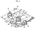
- FIG. 4 another embodiment of the present invention exhibits a structure where the geared portions 211d and 221d are directly formed on the rotating arms 211 and 221.
- the rotation directions of the rotating arms 211 and 221 are determined according to the rotation direction of the driving motor 230 as above. Hence, the interval between the reel tables 210 and 220 can be adjusted. Also, the rotation angle of the rotating arms 211 and 221 can be restricted by the stoppers 217a, 217b, 227a and 227b.
- a means for adjusting the interval of the two reel tables 210 and 220 has the following structure.
- the parts of Figure 4 that are the same as those described in Figures 2 and 3 are indicated by the same reference numerals and nomenclatures.
- the arc-shaped holes 200a and 200b are symmetrically formed on the deck 200.
- the first and second fixed shafts 218 and 228 are fixedly installed between the two holes 200a and 200b separated by a predetermined distance.
- the rotating arms 211 and 221 are rotatably installed at the first and second fixed shafts 218 and 228, respectively. The rotating arms 211 and 221 are rotated by means of a predetermined rotating means.
- the motors 216 and 226 are each installed under the rotating arms 211 and 221, and the reel tables 210 and 220 are fixed to the shafts of the motors 216 and 226, respectively.
- the above-mentioned rotating means is structured as follows. Geared portions 211d and 221d are formed at the ends of rotating arm 211 and 221, in which the geared portions 211d and 221d are engaged with each other.
- the driving motor 230 for generating a driving force is installed at one side of the deck 200.
- the driving motor 230 and the geared portion 231d are connected via the gear train 232.
- the rotating arms 211 and 221 are rotated simultaneously by the driving force of the driving motor 230.
- the preventing means comprises: protrusions 211a and 221a formed at the radial ends of the rotating arms 211 and 221, respectively, stoppers 217a, 217b, 227a and 227b for limiting the rotation of the arms 211 and 221 formed on the deck 200. Accordingly, the rotation of the rotating arms 211 and 221 are restricted by the stoppers.
- the advantages of the reel table transferring mechanism of the magnetic recording/reproducing apparatus are as follows.
Landscapes
- Gear Transmission (AREA)
- Manipulator (AREA)
- Feeding And Guiding Record Carriers (AREA)
- Winding Of Webs (AREA)
- Transmission Devices (AREA)
- Automatic Tape Cassette Changers (AREA)
- Holding Or Fastening Of Disk On Rotational Shaft (AREA)
Abstract
Description
- The present invention relates to a reel table transferring mechanism of a magnetic recording/reproducing apparatus such as VTR's, camcorders or digital-video cassette recorders (D-VCR's), and more particularly, to a reel table transferring mechanism of a magnetic recording/reproducing apparatus, in which a cassette having one of two different sizes is selectively loaded.
- Generally, a pair of reel tables are provided in a magnetic recording/reproducing apparatus using a magnetic tape, such as a VTR, Camcorder, or D-VCR. A mechanism has recently been suggested in Japan Television Associates Vol. 44, No.9, p.1216, in which a pair of reel tables can move to select one of at least two tape cassettes 300 and 400 of different sizes as shown in Figure 1. Reel tables 21 and 22 are supported to slide along respective pairs of
guide shafts Timing belts motor 27 enable the reel tables 21 and 22 to move, varying the distance therebetween to enable loading of tape cassettes of different sizes. - In the above-described mechanism in which the reel tables 21 and 22 move linearly, installing the required
guide rail pairs - Also, since each reel table is coupled by just one stopper at each side thereof, the reel tables 21 and 22 are unstable. Hence, the reel tables 21 and 22 may generate noise and the mechanism may not operate smoothly.
- With a view to solving or reducing the above problems, it is an aim of preferred embodiments of the present invention to provide a reel table transferring mechanism of a magnetic recording/reproducing apparatus by which a smoother transfer of the reel table can be achieved.
- According, to a first aspect of the present invention, there is provided a reel table transferring mechanism of a magnetic recording/reproducing apparatus comprising: a deck where first and second arc-shaped holes shape are formed; first and second fixed shafts separated by a predetermined distance fixed to the deck; a pair of rotating arms, rotatably installed around the first and second fixed shafts, by which reel tables for receiving a tape cassette are supported; a pair of driving arms, each having geared portions that engage with each other, rotatably coupled to the first and second fixed shafts, respectively; a driving motor for driving the driving arms by a gear train coupled to the geared portions of the driving arms; and connecting means for coupling the driving arms with the rotating arms so that a driving force of the driving motor is transferred to each of the rotating arms.
- Here, it is preferred in the present invention that motors for driving the reel tables are installed at the rotating arms, respectively.
- Also, the connecting means preferably has a structure consisting of cavities formed at the bottoms of the driving arms, respectively; indented portions formed on the rotating arms corresponding to the cavities, respectively; and a coil spring inserted respectively between the cavities and the indented portions.
- It is preferred in the present invention to further comprise a preventing means for preventing excessive rotation of the rotating arms, and that the preventing means comprises: protrusions formed on the rotating arms; and stoppers, formed on the deck, for restricting the rotation of the rotating arms by contacting the protrusions.
- In a reel table transferring mechanism of a magnetic recording/reproducing apparatus according to another aspect of the present invention, having a pair of reel tables, installed on a deck, on which reels of a tape cassette are placed, and adjusting means for adjusting the interval between said reel tables so that tape cassettes of different sizes can be selectively placed on said reel tables, the adjusting means comprises: first and second fixed shafts fixed to the deck being separated at a predetermined interval; a pair of rotating arms, by which the reel tables are supported, rotatably installed around the first and second fixed shafts; and rotating means for rotating the rotating arms, whereby the distance between the reel tables is adjusted by the rotation of the rotating arms.
- Here, preferably the rotating means includes a geared portion each at the ends of the rotating arms, the geared portions being engaged with each other, and one geared portion of the rotating arms is controlled by a driving force of a driving motor via a gear train, and that preferably first and second arc-shaped holes corresponding to the rotation of the reel tables are formed on the deck, and motors for driving the reel tables are installed under the rotating arms, respectively.
- Preferably, the mechanism further comprises preventing means for preventing excessive rotation of said rotating arms.
- Said preventing means preferably comprises: protrusions formed on said rotating arms, respectively; and stoppers formed on said deck, for restricting the rotation of said rotating arms by contacting said protrusions.
- For a better understanding of the invention, and to show how embodiments of the same may be carried into effect, reference will now be made, by way of example, to the accompanying diagrammatic drawings, in which:
- Figure 1 is a plan view schematically illustrating a conventional reel table transferring mechanism;
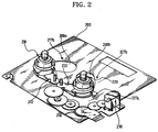
- Figure 2 is a perspective view illustrating a reel table transferring mechanism according to one embodiment of the present invention;
- Figure 3 is an exploded perspective view showing the essential parts of the mechanism of Figure 2;
- Figure 4 is a perspective view illustrating a reel table transferring mechanism according to another embodiment of the present invention; and
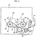
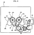
- Figures 5 and 6 are plan views respectively illustrating the transferred positions of the reel tables according to one of the embodiments of the present invention.
- Referring to Figures 2 and 3 showing the reel table transferring mechanism of a magnetic recording/reproducing apparatus according to an embodiment of the present invention, first and second arc-
shaped holes deck 200. First and second fixedshafts deck 200 being separated at a predetermined interval between the first andsecond holes arms shafts arms portion shafts portions arms arms springs washers - A
driving motor 230 for generating a driving force is installed at one side of thedeck 200. The gear driving force is transmitted to the gearedportion 222a from the drivingmotor 230 via agear train 232. - A connecting means for connecting the
driving arms arms motor 230 can be transmitted to the respective rotatingarms cavities arms portions 211c and 221c formed on the respective rotatingarms cavities coil springs cavities portions 211c and 221c, respectively. That is, thecoil springs cavities portions 211c and 221c, respectively. Thus, the drivingmotor 230 transmits power to the rotatingarms coil springs - Here, the reel tables 210 and 220 and the
motors arms coupling holes motors arm plates holes coupling holes supports motors holes plates - Meanwhile, a preventing means for preventing excess rotation of the rotating
arms protrusions arms stoppers deck 200 for limiting the rotation of thearms stoppers protrusions - The operation and effects of the reel table transferring mechanism according to the present invention will now be described.
- Referring to Figures 2, 3 and 5, when a large tape cassette is loaded, the distance between the reel tables 210 and 220 is adjusted as follows. First, when the driving
motor 230 is driven so that the last gear of thegear train 232 engaged with thegear portion 222a of the drivingarm 222 rotates counterclockwise, the two engaged rotatingarms protrusions arms stoppers arms arms coil springs motor 230. Here, the rotatingarms stoppers springs - When a small tape cassette is loaded, referring to Figures 2, 3 and 6, the distance between the reel tables 210 and 220 is controlled as follows. When the driving
motor 230 is driven so that the final gear of thegear train 232 which is engaged with thegear portions 222a of the drivingarm 222 rotates clockwise, the two engaged rotatingarms protrusions arms stoppers arms motor 230 depressing thecoil springs arms respective stoppers springs - On the other hand, referring to Figure 4, another embodiment of the present invention exhibits a structure where the geared
portions arms arms driving motor 230 as above. Hence, the interval between the reel tables 210 and 220 can be adjusted. Also, the rotation angle of the rotatingarms stoppers - In a mechanism according to the embodiment of Figure 4, a means for adjusting the interval of the two reel tables 210 and 220 has the following structure. Here, the parts of Figure 4 that are the same as those described in Figures 2 and 3 are indicated by the same reference numerals and nomenclatures.
- The arc-
shaped holes deck 200. The first and second fixedshafts holes arms shafts arms - The
motors arms motors - The above-mentioned rotating means is structured as follows. Geared
portions arm portions motor 230 for generating a driving force is installed at one side of thedeck 200. The drivingmotor 230 and the geared portion 231d are connected via thegear train 232. Thus, the rotatingarms motor 230. - As described above, a means for preventing excessive rotation of the rotating
arms protrusions arms stoppers arms deck 200. Accordingly, the rotation of the rotatingarms - As described above, the advantages of the reel table transferring mechanism of the magnetic recording/reproducing apparatus according to embodiments of the present invention are as follows.
- First, since the interval between the reel tables 210 and 220 is adjusted by the rotary
rotating arms - Second, since the reel tables 210 and 220 are firmly pressed by the spring force, the reel running becomes smooth and less noise is generated than the conventional mechanism.
- The reader's attention is directed to all papers and documents which are filed concurrently with or previous to this specification in connection with this application and which are open to public inspection with this specification, and the contents of all such papers and documents are incorporated herein by reference.
- All of the features disclosed in this specification (including any accompanying claims, abstract and drawings), and/or all of the steps of any method or process so disclosed, may be combined in any combination, except combinations where at least some of such features and/or steps are mutually exclusive.
- Each feature disclosed in this specification (including any accompanying claims, abstract and drawings), may be replaced by alternative features serving the same, equivalent or similar purpose, unless expressly stated otherwise. Thus, unless expressly stated otherwise, each feature disclosed is one example only of a generic series of equivalent or similar features.
- The invention is not restricted to the details of the foregoing embodiment(s). The invention extends to any novel one, or any novel combination, of the features disclosed in this specification (including any accompanying claims, abstract and drawings), or to any novel one, or any novel combination, of the steps of any method or process so disclosed.
Claims (10)
- A reel table transferring mechanism of a magnetic recording/reproducing apparatus comprising:a deck (200) where first and second arc-shaped holes (200a, 200b) are formed;first and second fixed shafts (218, 228) separated by a predetermined distance fixed to said deck (200);a pair of rotating arms (211, 221), rotatably installed around said first and second fixed shafts (218, 228), by which reel tables (210, 220) for receiving a tape cassette are supported;a pair of driving arms (212, 222), each having geared portions (212a, 222a) that engage with each other, rotatably coupled to said first and second fixed shafts (218, 228), respectively;a driving motor (230) for driving said driving arms (212, 222) by a gear train (232) coupled to said geared portions (222a) of said driving arms (212, 222); andconnecting means for coupling said driving arms (212, 222) with said rotating arms (211, 221) so that a driving force of said driving motor (230) is transferred to each of said rotating arms (211, 221).
- A reel table transferring mechanism of a magnetic recording/reproducing apparatus as claimed in claim 1, wherein motors (216, 226) for driving said reel tables are installed at said rotating arms (211, 221), respectively.
- A reel table transferring mechanism of a magnetic recording/reproducing apparatus as claimed in claim 1 or 2, wherein said connecting means comprises:cavities (212b, 222b) formed at the bottoms of said driving arms (212, 222), respectively;indented portions (211c, 221c) formed on said rotating arms (211, 221) corresponding to said cavities (212b, 222b), respectively; anda coil spring (213, 223) inserted respectively between said cavities and said indented portions (211c, 221c).
- A reel table transferring mechanism of a magnetic recording/reproducing apparatus as claimed in claim 1, 2 or 3, further comprising preventing means for preventing excessive rotation of said rotating arms (211, 221).
- A reel table transferring mechanism of a magnetic recording/reproducing apparatus as claimed in claim 4, wherein said preventing means comprises:protrusions (211a, 221a) formed on said rotating arms (211, 221); andstoppers (217a, 217b, 227a, 227b), formed on said deck (200), for restricting the rotation of said rotating arms (211, 221) by contacting said protrusions (211a, 221a).
- A reel table transferring mechanism of a magnetic recording/reproducing apparatus having a pair of reel tables (210, 220), installed on a deck (200), on which reels of a tape cassette are placed, and adjusting means for adjusting the interval between said reel tables (210, 220) so that tape cassettes of different sizes can be selectively placed on said reel tables (210, 220), wherein said adjusting means comprises:first and second fixed shafts (218, 228) fixed to said deck (200) being separated at a predetermined interval;a pair of rotating arms (211, 221), by which said reel tables (210, 220) are supported, rotatably installed around said first and second fixed shafts (218, 228); androtating means for rotating said rotating arms (211, 221), whereby the distance between said reel tables (210, 220) is adjusted by the rotation of said rotating arms (211, 221).
- A reel table transferring mechanism of a magnetic recording/reproducing apparatus as claimed in claim 6, wherein said rotating means includes geared portions (211d, 221d) at ends of said rotating arms (211, 221), said geared portions (211d, 221d) being engaged with each other, and one geared portion (221d) of said rotating arms (211, 221) is controlled by a driving force of a driving motor (230) via a gear train (232).
- A reel table transferring mechanism of a magnetic recording/reproducing apparatus as claimed in claim 6 or 7, wherein first and second arc-shaped holes (200a, 200b) corresponding to the rotation of said reel tables (210, 220) are formed on said deck (200), and motors (216, 226) for driving said reel tables (210, 220) are installed under said rotating arms (211, 221), respectively.
- A reel table transferring mechanism of a magnetic recording/reproducing apparatus as claimed in claim 6, 7 or 8, further comprising preventing means for preventing excessive rotation of said rotating arms (211, 221).
- A reel table transferring mechanism of a magnetic recording/reproducing apparatus as claimed in claim 6, 7, 8 or 9, wherein said preventing means comprises:protrusions (211a, 221a) formed on said rotating arms (211, 221), respectively; andstoppers (217a, 217b, 227a, 227b), formed on said deck (200), for restricting the rotation of said rotating arms (211, 221) by contacting said protrusions (211a, 221a).
Applications Claiming Priority (2)
| Application Number | Priority Date | Filing Date | Title |
|---|---|---|---|
| KR1019950012459A KR0183711B1 (en) | 1995-05-18 | 1995-05-18 | Reel table moving mechanism of magnetic record/reproduce apparatus |
| KR9512459 | 1995-05-18 |
Publications (3)
| Publication Number | Publication Date |
|---|---|
| EP0743646A2 true EP0743646A2 (en) | 1996-11-20 |
| EP0743646A3 EP0743646A3 (en) | 1997-01-22 |
| EP0743646B1 EP0743646B1 (en) | 2001-09-26 |
Family
ID=19414847
Family Applications (1)
| Application Number | Title | Priority Date | Filing Date |
|---|---|---|---|
| EP96303536A Expired - Lifetime EP0743646B1 (en) | 1995-05-18 | 1996-05-17 | Reel table transferring mechanism of magnetic recording/reproducing apparatus |
Country Status (6)
| Country | Link |
|---|---|
| US (1) | US5873539A (en) |
| EP (1) | EP0743646B1 (en) |
| JP (1) | JP3073694B2 (en) |
| KR (1) | KR0183711B1 (en) |
| CN (1) | CN1139267A (en) |
| DE (1) | DE69615446T2 (en) |
Families Citing this family (1)
| Publication number | Priority date | Publication date | Assignee | Title |
|---|---|---|---|---|
| US7097125B2 (en) * | 2003-06-27 | 2006-08-29 | Certance Llc | Tape drive with automatic adaptation for different size tape cassettes |
Citations (3)
| Publication number | Priority date | Publication date | Assignee | Title |
|---|---|---|---|---|
| DE3234854A1 (en) * | 1981-09-30 | 1983-05-05 | Kabushiki Kaisha Takeuchi Sangyo, Kawasaki, Kanagawa | Audio tape apparatus |
| US4903149A (en) * | 1987-03-03 | 1990-02-20 | Sony Corporation | Tape cassette loading system for a magnetic recording and reproducing apparatus |
| EP0463786A2 (en) * | 1990-06-19 | 1992-01-02 | Sony Corporation | Cassette loading devices for accommodating cassettes of different sizes in tape cassette recording and/or reproducing apparatus |
Family Cites Families (4)
| Publication number | Priority date | Publication date | Assignee | Title |
|---|---|---|---|---|
| US4873593A (en) * | 1987-11-05 | 1989-10-10 | Ampex Corporation | Multi-cassette indexing mechanism for a tape transport |
| JPH02285546A (en) * | 1989-04-27 | 1990-11-22 | Sony Corp | Moving stand positioning mechanism for reel base shift device |
| JP3094611B2 (en) * | 1991-12-27 | 2000-10-03 | ソニー株式会社 | Tape supply winding device and tape cassette used in the device |
| JPH07130045A (en) * | 1993-11-02 | 1995-05-19 | Canon Inc | Rotary body moving device |
-
1995
- 1995-05-18 KR KR1019950012459A patent/KR0183711B1/en not_active IP Right Cessation
-
1996
- 1996-05-15 JP JP08120389A patent/JP3073694B2/en not_active Expired - Lifetime
- 1996-05-17 US US08/650,901 patent/US5873539A/en not_active Expired - Fee Related
- 1996-05-17 DE DE69615446T patent/DE69615446T2/en not_active Expired - Fee Related
- 1996-05-17 CN CN96100280A patent/CN1139267A/en active Pending
- 1996-05-17 EP EP96303536A patent/EP0743646B1/en not_active Expired - Lifetime
Patent Citations (3)
| Publication number | Priority date | Publication date | Assignee | Title |
|---|---|---|---|---|
| DE3234854A1 (en) * | 1981-09-30 | 1983-05-05 | Kabushiki Kaisha Takeuchi Sangyo, Kawasaki, Kanagawa | Audio tape apparatus |
| US4903149A (en) * | 1987-03-03 | 1990-02-20 | Sony Corporation | Tape cassette loading system for a magnetic recording and reproducing apparatus |
| EP0463786A2 (en) * | 1990-06-19 | 1992-01-02 | Sony Corporation | Cassette loading devices for accommodating cassettes of different sizes in tape cassette recording and/or reproducing apparatus |
Also Published As
| Publication number | Publication date |
|---|---|
| JPH0922551A (en) | 1997-01-21 |
| CN1139267A (en) | 1997-01-01 |
| DE69615446D1 (en) | 2001-10-31 |
| KR960042608A (en) | 1996-12-21 |
| EP0743646A3 (en) | 1997-01-22 |
| JP3073694B2 (en) | 2000-08-07 |
| KR0183711B1 (en) | 1999-04-15 |
| EP0743646B1 (en) | 2001-09-26 |
| DE69615446T2 (en) | 2002-06-06 |
| US5873539A (en) | 1999-02-23 |
Similar Documents
| Publication | Publication Date | Title |
|---|---|---|
| EP0743646A2 (en) | Reel table transferring mechanism of magnetic recording/reproducing apparatus | |
| EP0747902B1 (en) | Tape cassette loading mechanism in magnetic recording/reproducing apparatus | |
| CA1054175A (en) | Drive mechanism for computer form feeder apparatus | |
| EP0369476B1 (en) | A normal/reverse mode changing mechanism for tape transport apparatus | |
| EP0743647B1 (en) | Reel braking mechanism of magnetic recording/reproducing apparatus | |
| US5730380A (en) | Reel table transferring mechanism for magnetic recording/reproducing apparatus | |
| JPH01120458A (en) | Power transmission | |
| JP3055000B2 (en) | Loading mechanism of magnetic recording / reproducing device | |
| US5234180A (en) | Bi-directional rewinding apparatus for 8 mm video tape | |
| JP2753383B2 (en) | Magnetic recording / reproducing device | |
| JPH0455231A (en) | Sheet material feeding device | |
| JP3150360B2 (en) | Sorter tray moving mechanism | |
| KR0147566B1 (en) | Power transmission device for tape recorder | |
| US5862027A (en) | Cam gear driving apparatus of a video cassette recorder | |
| KR0116649Y1 (en) | Signal transferring apparatus of a tape recorder | |
| JPH026519Y2 (en) | ||
| KR0130088Y1 (en) | Reel brake device | |
| JPS5919962Y2 (en) | Rotation transmission path switching device | |
| JPH11231590A (en) | Drive transmitting device | |
| JPH10247225A (en) | Ic card reader | |
| JPH07130043A (en) | Magnetic recording and reproducing device | |
| JPS60103542A (en) | Reel drive device of tape recorder | |
| JPS6386135A (en) | Tape driving mechanism | |
| KR19980068071A (en) | Reel table moving mechanism of tape recorder | |
| JPH08167198A (en) | Reel braking mechanism |
Legal Events
| Date | Code | Title | Description |
|---|---|---|---|
| PUAI | Public reference made under article 153(3) epc to a published international application that has entered the european phase |
Free format text: ORIGINAL CODE: 0009012 |
|
| AK | Designated contracting states |
Kind code of ref document: A2 Designated state(s): DE FR GB |
|
| PUAL | Search report despatched |
Free format text: ORIGINAL CODE: 0009013 |
|
| AK | Designated contracting states |
Kind code of ref document: A3 Designated state(s): DE FR GB |
|
| 17P | Request for examination filed |
Effective date: 19970705 |
|
| 17Q | First examination report despatched |
Effective date: 20000120 |
|
| GRAG | Despatch of communication of intention to grant |
Free format text: ORIGINAL CODE: EPIDOS AGRA |
|
| GRAG | Despatch of communication of intention to grant |
Free format text: ORIGINAL CODE: EPIDOS AGRA |
|
| GRAH | Despatch of communication of intention to grant a patent |
Free format text: ORIGINAL CODE: EPIDOS IGRA |
|
| GRAH | Despatch of communication of intention to grant a patent |
Free format text: ORIGINAL CODE: EPIDOS IGRA |
|
| GRAA | (expected) grant |
Free format text: ORIGINAL CODE: 0009210 |
|
| AK | Designated contracting states |
Kind code of ref document: B1 Designated state(s): DE FR GB |
|
| REF | Corresponds to: |
Ref document number: 69615446 Country of ref document: DE Date of ref document: 20011031 |
|
| REG | Reference to a national code |
Ref country code: GB Ref legal event code: IF02 |
|
| ET | Fr: translation filed | ||
| PG25 | Lapsed in a contracting state [announced via postgrant information from national office to epo] |
Ref country code: GB Free format text: LAPSE BECAUSE OF NON-PAYMENT OF DUE FEES Effective date: 20020517 |
|
| PLBE | No opposition filed within time limit |
Free format text: ORIGINAL CODE: 0009261 |
|
| STAA | Information on the status of an ep patent application or granted ep patent |
Free format text: STATUS: NO OPPOSITION FILED WITHIN TIME LIMIT |
|
| 26N | No opposition filed | ||
| PG25 | Lapsed in a contracting state [announced via postgrant information from national office to epo] |
Ref country code: DE Free format text: LAPSE BECAUSE OF NON-PAYMENT OF DUE FEES Effective date: 20021203 |
|
| GBPC | Gb: european patent ceased through non-payment of renewal fee |
Effective date: 20020517 |
|
| PG25 | Lapsed in a contracting state [announced via postgrant information from national office to epo] |
Ref country code: FR Free format text: LAPSE BECAUSE OF NON-PAYMENT OF DUE FEES Effective date: 20030131 |
|
| REG | Reference to a national code |
Ref country code: FR Ref legal event code: ST |