EP0747786A2 - Verfahren zum Übertragen eines mit Flüssigkeit erzeugten Bildes - Google Patents
Verfahren zum Übertragen eines mit Flüssigkeit erzeugten Bildes Download PDFInfo
- Publication number
- EP0747786A2 EP0747786A2 EP96304269A EP96304269A EP0747786A2 EP 0747786 A2 EP0747786 A2 EP 0747786A2 EP 96304269 A EP96304269 A EP 96304269A EP 96304269 A EP96304269 A EP 96304269A EP 0747786 A2 EP0747786 A2 EP 0747786A2
- Authority
- EP
- European Patent Office
- Prior art keywords
- liquid
- image
- developer
- transferring
- solid
- Prior art date
- Legal status (The legal status is an assumption and is not a legal conclusion. Google has not performed a legal analysis and makes no representation as to the accuracy of the status listed.)
- Withdrawn
Links
Images

Classifications
-
- G—PHYSICS
- G03—PHOTOGRAPHY; CINEMATOGRAPHY; ANALOGOUS TECHNIQUES USING WAVES OTHER THAN OPTICAL WAVES; ELECTROGRAPHY; HOLOGRAPHY
- G03G—ELECTROGRAPHY; ELECTROPHOTOGRAPHY; MAGNETOGRAPHY
- G03G9/00—Developers
- G03G9/08—Developers with toner particles
- G03G9/12—Developers with toner particles in liquid developer mixtures
- G03G9/13—Developers with toner particles in liquid developer mixtures characterised by polymer components
- G03G9/133—Graft-or block polymers
-
- G—PHYSICS
- G03—PHOTOGRAPHY; CINEMATOGRAPHY; ANALOGOUS TECHNIQUES USING WAVES OTHER THAN OPTICAL WAVES; ELECTROGRAPHY; HOLOGRAPHY
- G03G—ELECTROGRAPHY; ELECTROPHOTOGRAPHY; MAGNETOGRAPHY
- G03G15/00—Apparatus for electrographic processes using a charge pattern
- G03G15/14—Apparatus for electrographic processes using a charge pattern for transferring a pattern to a second base
- G03G15/16—Apparatus for electrographic processes using a charge pattern for transferring a pattern to a second base of a toner pattern, e.g. a powder pattern, e.g. magnetic transfer
- G03G15/1605—Apparatus for electrographic processes using a charge pattern for transferring a pattern to a second base of a toner pattern, e.g. a powder pattern, e.g. magnetic transfer using at least one intermediate support
- G03G15/161—Apparatus for electrographic processes using a charge pattern for transferring a pattern to a second base of a toner pattern, e.g. a powder pattern, e.g. magnetic transfer using at least one intermediate support with means for handling the intermediate support, e.g. heating, cleaning, coating with a transfer agent
-
- G—PHYSICS
- G03—PHOTOGRAPHY; CINEMATOGRAPHY; ANALOGOUS TECHNIQUES USING WAVES OTHER THAN OPTICAL WAVES; ELECTROGRAPHY; HOLOGRAPHY
- G03G—ELECTROGRAPHY; ELECTROPHOTOGRAPHY; MAGNETOGRAPHY
- G03G9/00—Developers
- G03G9/08—Developers with toner particles
- G03G9/12—Developers with toner particles in liquid developer mixtures
-
- G—PHYSICS
- G03—PHOTOGRAPHY; CINEMATOGRAPHY; ANALOGOUS TECHNIQUES USING WAVES OTHER THAN OPTICAL WAVES; ELECTROGRAPHY; HOLOGRAPHY
- G03G—ELECTROGRAPHY; ELECTROPHOTOGRAPHY; MAGNETOGRAPHY
- G03G9/00—Developers
- G03G9/08—Developers with toner particles
- G03G9/12—Developers with toner particles in liquid developer mixtures
- G03G9/125—Developers with toner particles in liquid developer mixtures characterised by the liquid
-
- G—PHYSICS
- G03—PHOTOGRAPHY; CINEMATOGRAPHY; ANALOGOUS TECHNIQUES USING WAVES OTHER THAN OPTICAL WAVES; ELECTROGRAPHY; HOLOGRAPHY
- G03G—ELECTROGRAPHY; ELECTROPHOTOGRAPHY; MAGNETOGRAPHY
- G03G9/00—Developers
- G03G9/08—Developers with toner particles
- G03G9/12—Developers with toner particles in liquid developer mixtures
- G03G9/13—Developers with toner particles in liquid developer mixtures characterised by polymer components
-
- G—PHYSICS
- G03—PHOTOGRAPHY; CINEMATOGRAPHY; ANALOGOUS TECHNIQUES USING WAVES OTHER THAN OPTICAL WAVES; ELECTROGRAPHY; HOLOGRAPHY
- G03G—ELECTROGRAPHY; ELECTROPHOTOGRAPHY; MAGNETOGRAPHY
- G03G2215/00—Apparatus for electrophotographic processes
- G03G2215/16—Transferring device, details
- G03G2215/1676—Simultaneous toner image transfer and fixing
- G03G2215/1695—Simultaneous toner image transfer and fixing at the second or higher order transfer point
Definitions
- This invention is generally directed a method of and apparatus for reproducing color images on an electrophotographic printing machine with liquid developer.
- One object of the present invention is to strive to minimize such problems.
- a method for transferring a liquid developer image on an intermediate surface to a final support substrate said liquid developer image having a liquid portion including a carrier fluid and having a solid portion including thermoplastic resin and pigment at ambient temperatures, including the steps of: heating the liquid developer image on the intermediate surface to a given temperature at least as that at which said solid portion and liquid portion form substantially two distinct liquid phases; and transferring the liquid developer image to the final support.
- an imaging method including: forming an electrostatic latent image; developing the electrostatic latent image with the liquid developer having a liquid portion including a carrier fluid and having a solid portion including thermoplastic resin and pigment at ambient temperatures; transferring the developed image onto an intermediate surface; heating the developed image on the intermediate surface to a given temperature at least as that at which said solid portion and liquid portion form substantially two distinct liquid phases; and transferring the developed image to a final support.
- a printing machine including: means for forming an electrostatic latent image on an imageable surface; means for developing the electrostatic latent image with the liquid developer having a liquid portion including a carrier fluid and having a solid portion including thermoplastic resin and pigment at ambient temperatures; means for transferring the developed image onto an intermediate member; a heater, in communication with an outer surface of said intermediate member, for heating said intermediate member to a given temperature so as to cause the solid portion and liquid portion of the developed image on the intermediate surface to form substantially two distinct liquid phases on the outer surface thereof; and means, defining a nip with the outer surface of said intermediate member, for transferring the developed image to a recording sheet passing through the nip defined by said intermediate member.
- the liquid developers suitable for the present invention generally comprise a liquid vehicle, toner particles, a charge control additive.
- the liquid medium may be any of several hydrocarbon liquids conventionally employed for liquid development processes, including hydrocarbons, such as high purity alkanes having from about 6 to about 14 carbon atoms, carrier fluids such as Norpar 15® and Isopar L® or Superla® and Isopar L® or a mixture of two or more of the above fluids.
- the amount of the liquid employed in the developer of the present invention is from about 90 to about 99.9 percent, and preferably from about 95 to about 99 percent by weight of the total developer dispersion.
- the total solids content of the developers is, for example, 0.1 to 10 percent by weight, preferably 0.3 to 3 percent, and more preferably, 0.5 to 2.0 percent by weight.
- charge directors include components such as (1) a protonated AB diblock copolymer of poly[2-dimethylammoniumethyl methacrylate bromide co-2-ethylhexyl methacrylate], poly[2-dimethylammoniumethyl methacrylate tosylate co-2-ethylhexyl methacrylate], poly[2-dimethylammoniumethyl methacrylate chloride co-2-ethylhexyl methacrylate], poly[2-dimethylammoniumethyl methacrylate bromide co-2-ethylhexyl acrylate], poly[2-dimethylammoniumethyl acrylate bromide co-2-ethylhexyl methacrylate], poly[2-dimethylammoniumethyl acrylate bromide co-2-ethylhexyl methacrylate], poly[2-dimethylammoniumethyl acrylate bromide co-2-ethylhexyl methacrylate], poly[2-dimethyl
- the charge director can be selected for the liquid developers in various effective amounts, such as for example in embodiments from about 0.5 percent to 80 percent by weight relative to developer solids and preferably 2 percent to 20 percent by weight relative to developer solids.
- Developer solids includes toner resin, pigment, and charge adjuvant. Without pigment the developer may be selected for the generation of a resist, a printing plate, and the like.
- Examples of other effective charge director for liquid toner particles include anionic glyceride, such as EMPHOS® D70-30C and EMPHOS® F27-85, two products sold by Witco Corporation, New York, NY; which are sodium salts of phosphated mono- and diglycerides with saturated and unsaturated substituents respectively, lecithin, Basic Barium Petronate, Neutral Barium Petronate, Basic Calcium Petronate, Neutral Calcium Petronate, oil soluble petroleum sulfonates, Witco Corporation, New York, NY, and metallic soap charge directors such as aluminum tristearate, aluminum distearate, barium, calcium, lead, and zinc stearates; cobalt, manganese, lead, and zinc lineolates, aluminum, calcium, and cobalt octoates; calcium and cobalt oleates; zinc palmitate; calcium, cobalt, manganese, lead, zinc resinates, and the like.
- Other effective charge directors include AB diblock copolymers of 2-e
- thermoplastic toner resin can be selected for the liquid developers of the present invention in effective amounts of, for example, in the range of about 99 percent to 40 percent of developer solids, and preferably 95 percent to 70 percent of developer solids, which developer solids includes the thermoplastic resin, optional pigment and charge control agent, and any other component that comprises the particles.
- suitable thermoplastic toner resin include ethylene vinyl acetate (EVA) copolymers (ELVAX® resins, E.I.
- polyesters such as a copolymer of acrylic or methacrylic acid and at least one alkyl ester of acrylic or methacrylic acid wherein alkyl is from 1 to about 20 carbon atoms like methyl methacrylate (50 to 90 percent)/methacrylic acid (0 to 20 percent/ethylhexyl acrylate (10 to 50 percent); and other acrylic resins including ELVACITE® acrylic resins (E.I. DuPont de Nemours and Company); or blends thereof.
- acrylic resins such as a copolymer of acrylic or methacrylic acid and at least one alkyl ester of acrylic or methacrylic acid wherein alkyl is from 1 to about 20 carbon atoms like methyl methacrylate (50 to 90 percent)/methacrylic acid (0 to 20 percent/ethylhexyl acrylate (10 to 50 percent); and other acrylic resins including ELVACITE® acrylic resins (E.I. DuPont de Nemours and Company); or blends thereof.
- Preferred copolymers are the copolymer of ethylene and an ⁇ - ⁇ -ethylenically unsaturated acid of either acrylic acid or methacrylic acid.
- NUCREL® like NUCREL 599®, NUCREL 699®, or NUCREL 960® are selected as the thermoplastic resin.
- the liquid developer of the present invention may optionally contain a colorant dispersed in the resin particles.
- Colorants such as pigments or dyes and mixtures thereof, are preferably present to render the latent image visible.
- the liquid electrostatic developer of the present invention can be prepared by a variety of known processes such as, for example, mixing in the mixture of high and low vapor pressure fluids, the thermoplastic resin, charging additive, and colorant in a manner that the resulting mixture contains, for example about 15 to about 30 percent by weight of solids; heating the mixture to a temperature of from about 70°C to about 130°C until a uniform dispersion is formed; adding an additional amount of nonpolar liquid sufficient to decrease the total solids concentration of the developer to about 10 to 20 percent by weight; cooling the dispersion to about 10°C to about 50°C; adding the charge adjuvant compound to the dispersion; and diluting the dispersion.
- the resin, colorant, and charge adjuvant may be added separately to an appropriate vessel such as, for example, an attritor, heated ball mill, heated vibratory mill, such as a Sweco Mill manufactured by Sweco Company, Los Angeles, CA, equipped with particulate media for dispersing and grinding, a Ross double planetary mixer (manufactured by Charles Ross and Son, Hauppauge, NY), or a two roll heated mill, which requires no particulate media.
- Useful particulate media include particulate materials like a spherical cylinder selected from the group consisting of stainless steel, carbon steel, alumina, ceramic, zirconia, silica and sillimanite. Carbon steel particulate media are particularly useful when colorants other than black are used.
- a typical diameter range for the particulate media is in the range of 0.04 to 0.5 inch (approximately 1.0 to approximately 13 millimeters).
- the mixture is heated to a temperature of from about 70°C to about 130°C, and preferably to about 75°C to about 110°C.
- the mixture may be ground in a heated ball mill or heated attritor at this temperature for about 15 minutes to 5 hours, and preferably about 60 to about 180 minutes. After grinding at the above temperatures, an additional amount of nonpolar liquid may be added to the dispersion.
- the amount of nonpolar liquid to be added at this point should be an amount sufficient to decrease the total solids concentration of the dispersion to from about 10 to about 20 percent by weight.
- the dispersion is then cooled to about 10°C to about 50°C, and preferably to about 15°C to about 30°C, while mixing is continued until the resin admixture solidifies or hardens. Upon cooling, the resin admixture precipitates out of the dispersant liquid. Cooling is accomplished by methods such as the use of a cooling fluid, such as water, ethylene glycol, and the like in a jacket surrounding the mixing vessel.
- a cooling fluid such as water, ethylene glycol, and the like in a jacket surrounding the mixing vessel.
- Cooling may be accomplished, for example, in the same vessel, such as the attritor, while simultaneously grinding with particulate media to prevent the formation of a gel or solid mass; without stirring to form a gel or solid mass, followed by shredding the gel or solid mass and grinding by means of particulate media; or with stirring to form a viscous mixture and grinding by means of particulate media.
- the resin precipitate is cold ground for about 1 to 36 hours, and preferably 2 to 6 hours. Additional liquid may be added at any step during the preparation of the liquid developer to facilitate grinding or to dilute the developer to the appropriate percent solids needed for developing. Methods for the preparation of liquid developers are illustrated in US-A-4,760,009; 5,017,451; 4,923,778 and 4,783,389, the disclosures of which are totally incorporated herein by reference.
- Methods of imaging are also encompassed by the present invention wherein after formation of a latent image on a photoconductive imaging member, see European Patent Application No. 95 307 772.4, the image is developed with the liquid toner illustrated herein by, for example, immersion of the photoconductor therein, followed by transfer and fixing of the image.
- FIG. 3 schematically depicts the various elements of an illustrative color electrophotographic printing machine incorporating the present invention therein. It will become evident from the following discussion that the present invention is equally well suited for use in a wide variety of printing machines and is not necessarily limited in its application to the particular embodiment depicted herein.
- the color copy process can begin by inputting a computer generated color image into the image processing unit 44.
- a digital signals which represent the blue, green, and red density signals of the image are converted in the image processing unit into four bitmaps: yellow (Y), cyan (C), magenta (M), and black (Bk).
- the bitmap represents the value of exposure for each pixel, the color components as well as the color separation.
- Image processing unit 44 may contain a shading correction unit, an undercolor removal unit (UCR), a masking unit, a dithering unit, a gray level processing unit, and other imaging processing sub-sytems known in the art.
- the image processing unit 44 can store bitmap information for subsequent images or can operate in a real time mode.
- Photoconductive member 100 preferably a belt of the type which is typically multilayered and has a substrate, a conductive layer, an optional adhesive layer, an optional hole blocking layer, a charge generating layer, a charge transport layer, and, in some embodiments, an anti-curl backing layer. It is preferred that the photoconductive imaging member employed in the present invention be infrared sensitive this allows improved transmittance through a cyan image.
- Belt 100 is charged by charging unit 101a.
- Raster output scanner (ROS) 20a and similarly ROS 20b, 20c and 20d are controlled by image processing unit 44, ROS 20a writes a first complementary color image bitmap information by selectively erasing charges on the belt 100.
- the ROS 20a writes the image information pixel by pixel in a line screen registration mode.
- DAD discharged area development
- CAD charged area development
- belt 100 is advance the electrostatic latent image to development station 103a.
- An electrode 16a positioned before the entrance to development zone 17a is electrically biased to generate an AC field just prior to the entrance to development zone 17a so as to disperse the toner particles substantially uniformly throughout the liquid carrier.
- the toner particles, disseminated through the liquid carrier pass by electrophoresis to the electrostatic latent image.
- the charge of the toner particles is opposite in polarity to the charge on the photoconductive surface.
- Development station 103a After the latent image is developed it is conditioned at development station 103a.
- Development station 103a also includes porous roller 18a having perforations through the roller skin covering.
- Roller 18a receives the developed image on belt 100 and conditions the image by reducing fluid content while inhibiting the departure of toner particles from the image, and by compacting the toner particles of the image.
- an increase in percent solids is provided to the developed image, thereby improving the quality of the developed image.
- the percent solids in the developed image is increased to more than increased to 20 percent solids.
- Porous roller 18a operates in conjunction with vacuum (not shown) for removal of liquid from the roller.
- a roller in pressure against the blotter roller 18a, may be used in conjunction with or in the place of the vacuum, to squeeze the absorbed liquid carrier from the blotter roller for deposit into a receptacle.
- a vacuum assisted liquid absorbing roller may also find useful application where the vacuum assisted liquid absorbing roller is in the form of a belt, whereby excess liquid carrier is absorbed through an absorbent foam layer.
- a belt used for collecting excess liquid from a region of liquid developed images is described in US-A-4,299,902 and 4,258,115, the relevant portions of which are hereby incorporated by reference herein.
- roller 18a rotates in a direction to impose against the "wet" image on belt 100.
- the porous body of roller 18 absorbs excess liquid from the surface of the image through the skin covering pores and perforations.
- the vacuum located on one end of the central cavity of the roller draws liquid that has permeated through roller 18 out through the cavity and deposits the liquid in a receptacle or some other location which will allow for either disposal or recirculation of the liquid carrier to a replenishing system.
- Porous roller 18a discharged of excess liquid, continues to rotate in direction 21 to provide a continuous absorption of liquid from image on belt 100.
- the image on belt 100 advances to lamp 34a where any residual charge left on the photoconductive surface is extinguished by flooding the photoconductive surface with light from lamp 34a.
- the development takes place for the second color for example magenta, as follows: the developed latent image on belt 100 is recharged with charging unit 100b.
- the developed latent image is re-exposed by ROS 20b.
- ROS 20b superimposes a second color image bitmap information over the previous developed latent image.
- roller 116 rotating in the direction of arrow 12, advances a liquid developer material 13 from the chamber of housing to development zone 17b.
- An electrode 16b positioned before the entrance to development zone 17b is electrically biased to generate an AC field just prior to the entrance to development zone 17b so as to disperse the toner particles substantially uniformly throughout the liquid carrier.
- the toner particles, disseminated through the liquid carrier pass by electrophoresis to the previous developed image.
- the charge of the toner particles is opposite in polarity to the charge on the previous developed image.
- Roller 18b receives the developed image on belt 100 and conditions the image by reducing fluid content while inhibiting the departure of toner particles from the image, and by compacting the toner particles of the image.
- the percent solids is more than 20 percent, however, the percent of solids can range between 15 percent and 40 percent.
- the image on belt 100 advances to lamps 34b where any residual charge left on the photoconductive surface is extinguished by flooding the photoconductive surface with light from lamp 34.
- Development takes place for the third color and fourth color, for example cyan and black in the same manner as described above, with the steps of charging, exposing, developing and conditioning for each color developed.
- the resultant image a multi layer image by virtue of the developing station 103a, 103b, 103c and 103d having black, yellow, magenta, and cyan, toner disposed therein advances to the intermediate transfer station. It should be evident to one skilled in the art that the color of toner at each development station could be in a different arrangement.
- the resultant image is electrostatically transferred to the intermediate member by charging device 111.
- the present invention takes advantage of the dimensional stability of the intermediate member to provide a uniform image deposition stage, resulting in a controlled image transfer gap and better image registration. Further advantages include reduced heating of the recording sheet as a result of the toner or marking particles being pre-melted, as well as the elimination of electrostatic transfer of charged particles to a recording sheet.
- Intermediate member 110 may be either a rigid roll or an endless belt having a path defined by a plurality of rollers in contact with the inner surface thereof.
- the multi layer image is conditioned by blotter roller 120 which receives the multi level image on intermediate member 110 and conditions the image by reducing fluid content while inhibiting the departure of toner particles from the image, and by compacting the toner particles of the image. Blotter roller 120 conditions the multi layer so that the image has a toner composition of 30 to 45 percent solids.
- stage B which essentially encompasses the region between when the multi layer image contact the surface of member 110 and when the multi layer is transferred to recording sheet 26.
- Stage B includes a heating element 32 to heat the multi layer image prior to transfer.
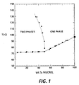
- a single phase can form at concentrations greater than about 50 percent Nucrel 599 and a temperature higher than the melting point. Accordingly, images of 50 percent solids are near the liquid-liquid phase separation boundary at which phase instability may occur.
- the multi layer image has composition of between 30 to 45 percent solids and is heated between 80 to 110°C. This causes two distinct liquid phases to form. A nearly pure carrier phase (called the minor phase) and a liquid phase containing about 50 percent toner resin (called the major phase).
- the liquefied toner particles are forced by a normal force N applied through backup pressure roll 36, into contact with the surface of recording sheet 26.
- the normal force N produces a nip pressure which is preferably about 100 to 200 psi, and may also be applied to the recording sheet via a resilient blade or similar spring-like member uniformly biased against the outer surface of the intermediate member across its width.
- the tackified toner particles wet the surface of the recording sheet, and due to greater attractive forces between the paper and the tackified particles, as compared to the attraction between the tackified particles and the liquid-phobic surface of member 110, the tackified particles are completely transferred to the recording sheet. Furthermore, as the image is transferred to recording sheet 26 in a tackified state, the image become permanent once they are advanced past transfix nip and allowed to cool.
- NUCREL 599® a copolymer of ethylene and methacrylic acid with a melt index at 190°C of 500 dg/minute, available from E.I. DuPont de Nemours & Company, Wilmington, DE
- FANAL PINKTM magenta pigment
- WITCO 22TM aluminum stearate WITCO 22TM
- NORPAR 15® carbon chain of 15 average
- the mixture was milled at 125 rpm in the attritor which was heated to 83°C to 96°C for 2 hours by running steam through the attritor jacket and then an additional 980.1 grams of NORPAR 15® were added to the attritor and the attritor contents were cooled to 23°C over 4 hours at a stir rate of 200 rpm by running cold water through the attritor jacket.
- An additional 1,532 grams of NORPAR 15® were added, and the mixture was separated by the use of a metal grate from the steel balls yielding a liquid toner concentrate of 7.19 percent solids wherein solids include resin, charge adjuvant, and pigment and 92.81 percent NORPAR 15®.
- the particle diameter was 2.02 microns average by area as measured with the Horiba Cappa 500. This toner concentrate was used to prepare developers of Controls and in Examples.
- GTP Sequential Group Transfer Polymerization
- EHMA 2-Ethylhexyl Methacrylate
- DMAEMA 2-Dimethylaminoethyl Methacrylate
- AB diblock copolymer precursors were prepared by a standard group transfer sequential polymerization procedure (GTP) wherein the ethylhexyl methacrylate monomer was first polymerized to completion and then the 2-dimethylaminoethyl methacrylate monomer was polymerized onto the living end of the ethylhexyl methacrylate polymer. All glassware was first baked out in an air convection oven at about 120 °C for about 16-18 hours.
- GTP group transfer sequential polymerization procedure
- the GTP initiator 15 ml of methyl trimethylsilyl dimethylketene acetal (12.87 grams; 0.0738 mole) is syringed into the polymerization vessel.
- the acetal was originally vacuum distilled and a middle fraction was collected and stored (under Argon) for polymerization initiation purposes.
- 0.1 ml of a 0.66M solution of tetrabutylammonium acetate (catalyst) in the same dry tetrahydrofuran was syringed into the polymerization vessel.
- the polymerization temperature peaked at about 50 °C.
- the GPC chromatogram was bimodal with the major peak occurring at 13.4-22.2 counts and the minor low molecular weight peak at 23.5-28.3 counts.
- a small (1-2 grams) portion of the AB diblock copolymer can be isolated for GPC and 1H-NMR analyses by precipitation into 10X its solution volume of methanol using vigorous mechanical agitation. The precipitated copolymer was then washed on the funnel with more methanol and was then dried overnight in vacuo (about 0.5 Torr) at about 50 °C.
- a second AB diblock copolymer was prepared as described in Example 2 using the same polymerization procedure, conditions, and quantities of the same materials except that more ketene acetal was used to initiate this GTP.
- 26 ml of the ketene acetal 22.31 grams;0.1280 mole were used to initiate the polymerization.
- the above monomer charges are equivalent to 78.5 mole percent EHMA and 21.5 mole percent DMAEMA which corresponds to an EHMA average DP of 16.4 (Mn of 3243) and a DMAEMA average DP of 4.5 (Mn of 703).
- GPC analysis as described in Example 2, indicated the major peak at 14.5 to 19.9 counts to have a number average molecular weight of 3,912 and a weight average molecular weight of 6,222 (MWD of 1.59). Two barely discernible broad low molecular weight peaks were located at 20 -25.1 and 25.1-30 counts.
- a third AB diblock copolymer was prepared as described in Example 3 using the same polymerization procedure and conditions except the polymerization scale was increased by a factor of three.
- 1H-NMR analysis of a 17.5% (g/dl) CDCl3 solution of an isolated portion of the unprotonated block copolymer indicated about a 77 to 78 mole percent EHMA repeat unit content and a 22 to 23 mole percent DMAEMA repeat unit content.
- GPC analysis of this unprotonated block copolymer, as described in Example 2 indicated the major peak at 14.4-22.6 counts to have a number average molecular weight of 2253 and a weight average molecular weight of 5978 (MWD of 2.65).
- a broad low molecular weight peak was located at 24-32 counts.
- a hydrogen bromide protonated charge director was prepared from this AB diblock copolymer solution in toluene as described in Example 5.
- AB diblock copolymer 150 grams from poly (2-ethylhexyl methacrylate-co-N,N-dimethylamino-N-ethyl methacrylate) prepared in Example 4 comprised of 18.23 weight percent 2-dimethylaminoethyl methacrylate (DMAEMA) repeat units and 81.77 weight percent 2-ethylhexyl methacrylate (EHMA) repeat units.
- DMAEMA 2-dimethylaminoethyl methacrylate
- EHMA 2-ethylhexyl methacrylate
- the 5 weight% Norpar 15 solution of poly(2-ethylhexyl methacrylate-co-N,N-dimethyl-N-ethyl methacrylate ammonium bromide) had a conductivity of 1700 to 1735 pmhos/cm and was used to charge liquid toner concentrate prepared in Example 1 to give a megenta liquid developer as described in Example 6.
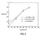
- a magenta liquid toner dispersion (developer) was prepared by taking liquid toner concentrate (6.74% solids in 4% Norpar 15 with the ink solids being thermoplastic resin, pigment, and charge adjuvant) from Example 1 and adding to Norpar 15, and charge director (5% solids in Norpar 15) from Example 5. This magenta developer was then used the following data was obtained as shown in figure 2:
- Test images consisting of solid patches with known percent solids concentrations prepared on paper.
- the patches were eraser fix tested by initially taking the optical density of each patch; rubbing the patch with a pink pearl eraser; and taking a final optical density.
- Figure 2 illustrates fix by Eraser test verses percent Norpar 15 with the intermediate heated to 100°C. The eraser test was preformed under various environmental conditions as illustrated on figure 2.
Landscapes
- Physics & Mathematics (AREA)
- General Physics & Mathematics (AREA)
- Wet Developing In Electrophotography (AREA)
- Electrostatic Charge, Transfer And Separation In Electrography (AREA)
- Color Electrophotography (AREA)
- Liquid Developers In Electrophotography (AREA)
- Fixing For Electrophotography (AREA)
Applications Claiming Priority (2)
| Application Number | Priority Date | Filing Date | Title |
|---|---|---|---|
| US473613 | 1995-06-07 | ||
| US08/473,613 US5839037A (en) | 1995-06-07 | 1995-06-07 | Method for transferring a liquid image |
Publications (2)
| Publication Number | Publication Date |
|---|---|
| EP0747786A2 true EP0747786A2 (de) | 1996-12-11 |
| EP0747786A3 EP0747786A3 (de) | 1999-03-03 |
Family
ID=23880285
Family Applications (1)
| Application Number | Title | Priority Date | Filing Date |
|---|---|---|---|
| EP96304269A Withdrawn EP0747786A3 (de) | 1995-06-07 | 1996-06-07 | Verfahren zum Übertragen eines mit Flüssigkeit erzeugten Bildes |
Country Status (3)
| Country | Link |
|---|---|
| US (1) | US5839037A (de) |
| EP (1) | EP0747786A3 (de) |
| JP (2) | JPH08334992A (de) |
Cited By (2)
| Publication number | Priority date | Publication date | Assignee | Title |
|---|---|---|---|---|
| EP0990958A3 (de) * | 1998-10-01 | 2001-01-24 | Samsung Electronics Co., Ltd. | Reinigungsgerät für eine Rolle eines elektrophotographischen Druckers mit Flüssigentwicklung |
| EP2713210A1 (de) * | 2012-09-28 | 2014-04-02 | Xeikon IP BV | Flüssigentwicklerdispersion für digitales Druckverfahren |
Families Citing this family (7)
| Publication number | Priority date | Publication date | Assignee | Title |
|---|---|---|---|---|
| ATE389672T1 (de) * | 1996-12-26 | 2008-04-15 | Fujifilm Corp | Verfahren zur herstellung eines copolymers |
| US5999201A (en) * | 1998-01-08 | 1999-12-07 | Xerox Corporation | Apparatus and method for forming a toner image with low toner pile height |
| US6253051B1 (en) | 1999-01-18 | 2001-06-26 | Nec Corporation | Wet-type image forming apparatus and method |
| US6606472B1 (en) * | 1999-03-17 | 2003-08-12 | Hitachi, Ltd. | Method and apparatus for forming color image |
| US6324368B1 (en) * | 2000-02-29 | 2001-11-27 | Toshiba Tec Kabushiki Kaisha | Image forming apparatus having a first squeeze roller rotated in an opposite direction to a photosensitive member |
| DE102006001771A1 (de) * | 2006-01-12 | 2007-07-19 | Röhm Gmbh | Verfahren zur Aufreinigung von (Meth)acrylaten |
| US8185020B2 (en) * | 2007-07-31 | 2012-05-22 | Konica Minolta Business Technologies, Inc. | Image forming apparatus and method for forming image with fine pigment and thermoplastic fine resin particles in a carrier liquid |
Family Cites Families (13)
| Publication number | Priority date | Publication date | Assignee | Title |
|---|---|---|---|---|
| US3847642A (en) * | 1972-01-20 | 1974-11-12 | Xerox Corp | Method for transferring electrostatographically formed images |
| US4684238A (en) * | 1986-06-09 | 1987-08-04 | Xerox Corporation | Intermediate transfer apparatus |
| US4708460A (en) * | 1986-07-25 | 1987-11-24 | Xerox Corporation | Simultaneous transfer and fusing in electrophotography |
| US4796048A (en) * | 1987-11-23 | 1989-01-03 | Xerox Corporation | Resilient intermediate transfer member and apparatus for liquid ink development |
| US5555185A (en) * | 1988-09-08 | 1996-09-10 | Indigo N.V. | Method and apparatus for imaging using an intermediate transfer member |
| US5276492A (en) * | 1989-08-14 | 1994-01-04 | Spectrum Sciences B.V. | Imaging method and apparatus |
| US5132743A (en) * | 1990-06-29 | 1992-07-21 | Olin Corporation | Intermediate transfer surface and method of color printing |
| US5136334A (en) * | 1991-05-17 | 1992-08-04 | Hewlett-Packard Company | Method and apparatus for preparing liquid tone for direct transfer to the media during electrophotographic printing |
| US5332642A (en) * | 1991-10-18 | 1994-07-26 | Xerox Corporation | Vacuum assisted dispersant reduction system |
| US5481341A (en) * | 1993-08-18 | 1996-01-02 | Xerox Corporation | Roller for controlling application of carrier liquid |
| US5424813A (en) * | 1994-05-23 | 1995-06-13 | Xerox Corporation | Apparatus and method for improved blotter roller permeability |
| US5570173A (en) * | 1994-10-31 | 1996-10-29 | Xerox Corporation | Color printer using liquid developer |
| US5573883A (en) * | 1995-06-05 | 1996-11-12 | Xerox Corporation | Method for developing an latent image with liquid developer having a mixture of a high vapor pressure carrier fluid and a low vapor pressure carrier fluid |
-
1995
- 1995-06-07 US US08/473,613 patent/US5839037A/en not_active Expired - Fee Related
-
1996
- 1996-05-29 JP JP8135130A patent/JPH08334992A/ja not_active Withdrawn
- 1996-05-29 JP JP8135131A patent/JPH09101683A/ja not_active Withdrawn
- 1996-06-07 EP EP96304269A patent/EP0747786A3/de not_active Withdrawn
Cited By (4)
| Publication number | Priority date | Publication date | Assignee | Title |
|---|---|---|---|---|
| EP0990958A3 (de) * | 1998-10-01 | 2001-01-24 | Samsung Electronics Co., Ltd. | Reinigungsgerät für eine Rolle eines elektrophotographischen Druckers mit Flüssigentwicklung |
| EP2713210A1 (de) * | 2012-09-28 | 2014-04-02 | Xeikon IP BV | Flüssigentwicklerdispersion für digitales Druckverfahren |
| CN103713486A (zh) * | 2012-09-28 | 2014-04-09 | 西康有限公司 | 用于数字印刷方法的液体显影剂分散体 |
| US9170515B2 (en) | 2012-09-28 | 2015-10-27 | Xeikon Ip Bv | Liquid developer dispersion for digital printing process |
Also Published As
| Publication number | Publication date |
|---|---|
| JPH08334992A (ja) | 1996-12-17 |
| EP0747786A3 (de) | 1999-03-03 |
| US5839037A (en) | 1998-11-17 |
| JPH09101683A (ja) | 1997-04-15 |
Similar Documents
| Publication | Publication Date | Title |
|---|---|---|
| EP0424093B1 (de) | Verfahren und Geräte zur Bilderzeugung | |
| US5021318A (en) | Process for forming secure images | |
| US5019477A (en) | Vinyltoluene and styrene copolymers as resins for liquid electrostatic toners | |
| JP3101624B2 (ja) | 電子写真用液体トナー | |
| US6546221B2 (en) | Developer storage and delivery system for liquid electrophotography | |
| EP0712507B1 (de) | Tonerteilchen mit modifizierter aufladbarkeit | |
| US4877698A (en) | Electrophotographic process for generating two-color images using liquid developer | |
| US5397672A (en) | Liquid developer compositions with block copolymers | |
| US6020103A (en) | Liquid developer, method of producing the liquid developer and image formation using the same | |
| EP0747786A2 (de) | Verfahren zum Übertragen eines mit Flüssigkeit erzeugten Bildes | |
| EP0709745B1 (de) | Vollfarben-Hochgeschwindigkeitsdruckmaschine | |
| US5573883A (en) | Method for developing an latent image with liquid developer having a mixture of a high vapor pressure carrier fluid and a low vapor pressure carrier fluid | |
| US4804601A (en) | Electrophotographic and electrographic imaging processes | |
| US4880720A (en) | Liquid developer compositions | |
| US5574547A (en) | Liquid electrophotographic reproduction machine employing heated carrier liquid | |
| US5200289A (en) | Charge control agent combination for a liquid toner | |
| US6989222B2 (en) | Liquid developer, method of manufacturing the liquid developer, and image forming method and apparatus | |
| US5206107A (en) | Siloxane surfactants as liquid developer additives | |
| CN100401210C (zh) | 由电记录调色剂形成的投影图像中减少的光散射 | |
| US6348292B1 (en) | Developer compositions and processes | |
| US6335136B1 (en) | Developer compositions and processes | |
| JP3077184B2 (ja) | 静電潜像現像用湿式現像剤 | |
| US6346357B1 (en) | Developer compositions and processes | |
| US6372402B1 (en) | Developer compositions and processes | |
| US6815136B1 (en) | Liquid developers and processes thereof |
Legal Events
| Date | Code | Title | Description |
|---|---|---|---|
| PUAI | Public reference made under article 153(3) epc to a published international application that has entered the european phase |
Free format text: ORIGINAL CODE: 0009012 |
|
| AK | Designated contracting states |
Kind code of ref document: A2 Designated state(s): DE FR GB |
|
| PUAL | Search report despatched |
Free format text: ORIGINAL CODE: 0009013 |
|
| AK | Designated contracting states |
Kind code of ref document: A3 Designated state(s): DE FR GB |
|
| 17P | Request for examination filed |
Effective date: 19990903 |
|
| 17Q | First examination report despatched |
Effective date: 20010424 |
|
| STAA | Information on the status of an ep patent application or granted ep patent |
Free format text: STATUS: THE APPLICATION IS DEEMED TO BE WITHDRAWN |
|
| 18D | Application deemed to be withdrawn |
Effective date: 20070103 |