EP0747314A1 - Core for winding a web of deformable material - Google Patents
Core for winding a web of deformable material Download PDFInfo
- Publication number
- EP0747314A1 EP0747314A1 EP96420181A EP96420181A EP0747314A1 EP 0747314 A1 EP0747314 A1 EP 0747314A1 EP 96420181 A EP96420181 A EP 96420181A EP 96420181 A EP96420181 A EP 96420181A EP 0747314 A1 EP0747314 A1 EP 0747314A1
- Authority
- EP
- European Patent Office
- Prior art keywords
- cover
- core
- web
- rigid member
- rigid
- Prior art date
- Legal status (The legal status is an assumption and is not a legal conclusion. Google has not performed a legal analysis and makes no representation as to the accuracy of the status listed.)
- Granted
Links
Images


Classifications
-
- B—PERFORMING OPERATIONS; TRANSPORTING
- B65—CONVEYING; PACKING; STORING; HANDLING THIN OR FILAMENTARY MATERIAL
- B65H—HANDLING THIN OR FILAMENTARY MATERIAL, e.g. SHEETS, WEBS, CABLES
- B65H75/00—Storing webs, tapes, or filamentary material, e.g. on reels
- B65H75/02—Cores, formers, supports, or holders for coiled, wound, or folded material, e.g. reels, spindles, bobbins, cop tubes, cans, mandrels or chucks
- B65H75/04—Kinds or types
- B65H75/08—Kinds or types of circular or polygonal cross-section
- B65H75/10—Kinds or types of circular or polygonal cross-section without flanges, e.g. cop tubes
-
- B—PERFORMING OPERATIONS; TRANSPORTING
- B65—CONVEYING; PACKING; STORING; HANDLING THIN OR FILAMENTARY MATERIAL
- B65H—HANDLING THIN OR FILAMENTARY MATERIAL, e.g. SHEETS, WEBS, CABLES
- B65H2701/00—Handled material; Storage means
- B65H2701/50—Storage means for webs, tapes, or filamentary material
- B65H2701/51—Cores or reels characterised by the material
- B65H2701/514—Elastic elements
-
- B—PERFORMING OPERATIONS; TRANSPORTING
- B65—CONVEYING; PACKING; STORING; HANDLING THIN OR FILAMENTARY MATERIAL
- B65H—HANDLING THIN OR FILAMENTARY MATERIAL, e.g. SHEETS, WEBS, CABLES
- B65H2701/00—Handled material; Storage means
- B65H2701/50—Storage means for webs, tapes, or filamentary material
- B65H2701/51—Cores or reels characterised by the material
- B65H2701/515—Cores or reels characterised by the material assembled from parts made of different materials
Landscapes
- Storage Of Web-Like Or Filamentary Materials (AREA)
Abstract
Description
- The invention relates to cores for winding webs of deformable material. More particularly, the invention relates to cores for winding webs, particularly, webs having edge portions which are thicker than a center portion, for example, knurl-edged webs.
- As described in published German Patent Application No. 3,610,557, a known problem in winding webs of paper onto a rigid core is that the adhesive tape used to secure the leading edge of the web to the core will cause an embossing of the paper for many turns of the web on the core. This embossing occurs by virtue of the finite thickness of the adhesive tape, and the high radial pressure which builds up as successive turns are wound on the core. The leading edge of the web also causes such embossings. Web containing such embossings is generally useless and has to be discarded.
- As described in published German Patent Application No. 3,610,557, a solution to the problem is to provide the core with a coating of elastically or plastically deformable material which deforms to accommodate the irregularity. As such, the web of the first turns on the core does not deform to accommodate the irregularity.
- When manufacturing webs, particularly webs of base material for photographic film, problems arise from the lack of uniformity in thickness (often referred to as "gage") across the web. One such problem arising from gage non-uniformity is known as gage bands. Gage bands occur, for example, when a region of increased thickness is at a lateral constant position. Then, as the web is wound on a core, the increased thickness regions of each turn will lie on top of the increased region of the previous turn. With gage bands, very high localized pressure often results in undesirable effects, such as abrasions, deformations, chemical changes, and physical changes. A known solution to gage bands is to make the margins thicker, or to knurl the margins of the web so that the protuberances produced by the knurling are higher than any gage increase likely to be encountered during normal manufacturing. Thus, when the web with the knurls along its two margins is wound on a conventional rigid core (with a non-deformable surface), the knurls in the margins wind on top of themselves. It is in these areas, rather than where the gage increases overlap one another, that the areas of high pressure are encountered. During manufacture, the margins containing the knurls are slit off and discarded, while the entire portion of the web between the knurls is assumed to be free from defects attributable to gage bands.
- It has been noted that when a web having knurled margins is wound onto a deformable core, such as described in published German Patent Application No. 3,610,557, if the deformable coating is soft enough to avoid undesirable embossings caused by the securing tape or leading edge, the very high pressures progressively created by the overlapping knurls cause the wound web to collapse radially inwards. Such collapses are not localized, and extend along the roll axially from the edges of the web toward the middle of the width of the roll. Permanent damage to the web occurs from the collapse, requiring an increased width of the web at the margins to be slit off and discarded, resulting in undesirable increased waste and correspondingly lower productivity.
- US-A-4,934,622, assigned to same assignee, incorporated herein by reference, describes a means for avoiding embossing and collapse of the wound roll. A first resilient sleeve is supported on a rigid member. A second and third sleeve, harder than the first sleeve, are positioned contiguous with the ends of the first sleeve, and are intended to underlie the margins of the web.
- While the above-identified apparatuses has achieved a certain degree of success, impressions can be created from the sharp transitions between the sleeves, and one particular core cannot accommodate webs of varying widths. For example, if a narrower web were wound onto the core, the knurls would be positioned over the first sleeve, causing the roll to collapse. Alternately, if a wider web were wound onto the core, the impression from the sharp transition would occur within the non-knurled, (that is, saleable) portion of the web.
- The present invention provides a modular design, thereby assisting in the reduction of manufacturing costs by allowing the modular components to be recycled or readily replaced. Further, a gradual transition zone allows a particular core size to accommodate webs of varying widths.
- Accordingly, a need exists for a core for winding a web of deformable material which accommodates various web widths, is not complex, can be manufactured inexpensively, affords modularity, avoids embossing, and is able to avoid collapse.
- An object of the invention is to provide a core which avoids embossing in the turns of a web wound on a core, the web having thicker edges (for example, knurls in its margins), and avoids the collapse of the wound web, particularly axially inward from the thicker edges of the web.
- Another object of the invention is to provide a core which is able to accommodate various widths of web material, is not complex, and can be manufactured inexpensively.
- A further object of the invention is to provide a core which is recyclable or modular.
- These objects are given only by way of illustrative examples; thus, other desirable objectives and advantages inherently achieved by the disclosed invention may occur or become apparent to those skilled in the art. The invention is defined by the appended claims.
- As claimed in one aspect of the invention, there is provided a core for winding a web of deformable material which is thicker along its margins. The core includes a rigid cylindrical member extending from a first end to a second end. A deformable cover having an outer diameter is supported by the rigid member throughout the length of the deformable cover. A first detachable cylindrical end member is attached to the rigid member at the first end, while a second detachable cylindrical end member is attached to the rigid member at the second end. The end members abut the rigid member and cover. The first and second end members have an outer diameter approximately equal to the outer diameter of the deformable cover and a hardness greater than the hardness of the deformable cover, such that the margins of the web overlay the first and second end members.
- As claimed in another aspect of the invention, the core includes a rigid cylindrical member extending from a first end to a second end. A deformable cover having a first hardness and an outer diameter extends from the first end to the second end and is supported by the rigid member. The portions of the cover supported at the first and second ends are treated by a process to provide a hardness harder than the hardness of the remaining portion of the cover, such that the margins of the web overlay the harder ends of the cover.
- As claimed in a further aspect of the invention, the core includes a rigid member having a first and second end and a first, second and center portion. The first portion is located at one end of the rigid member, while the second portion is located at the other end. The center portion being positioned intermediate the first and second portions. The center portion is cylindrical and has a first diameter. Each of the first and second ends including a taper providing cylindrical surfaces having a diameter greater than the first diameter. A deformable cover having an outer diameter extends from the first end to the second end and is supported by the rigid member, such that the margins of the web overlay the first and second ends of the rigid member.
- The core of the present invention avoids embossing and collapse, is able to accommodate webs of varying widths, and has fewer components, thus reducing the complexity and cost. In addition, the core is modular, such that each component can be recycled, or readily replaced if damaged.
- The foregoing and other objects, features, and advantages of the invention will be apparent from the following more particular description of the preferred embodiments of the invention, as illustrated in the accompanying drawings.
- FIG. 1 is a view of a core with the leading edge of a web secured thereto at the beginning of winding the web onto the core.
- FIG. 2 is a sectional view in a plane containing the axis, of a core in accordance with a first embodiment of the present invention;
- FIG. 3 is a sectional view of a core in a plane containing the axis, in accordance with the present invention;
- FIG. 4 is a sectional view of a core in a plane containing the axis, in accordance with the present invention;
- FIG. 5 is a sectional view of a core in a plane containing the axis, in accordance with the present invention.
- FIG. 6 is a sectional view of a core in a plane containing the axis, in accordance with the present invention;
- FIG. 7 is a sectional view of a core in accordance with the present invention;
- FIG. 8 is a side view of a core having key ways for coupling a core with drive means;
- FIG. 9 is a sectional view in a plane containing the axis, of a core in accordance with a second embodiment of the present invention;
- FIG. 10 is a sectional view in a plane containing the axis, of a core in accordance with a third embodiment of the present invention;
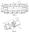
- FIG. 11 is a sectional view in a plane containing the axis, of the core of FIG. 9 having end rings for coupling the core with drive means;
- FIG. 12 is a isometric view of an end ring having integral keys matable with slots in a core;
- The following is a detailed description of the preferred embodiments of the invention, reference being made to the drawings in which the same reference numerals identify the same elements of structure in each of the several figures.
- FIG 1 illustrates a
core 10 for winding a web 12 of a flexible deformable material, for example, cellulose triacetate photographic film base. Web 12 hasknurls 14 in its margins which, in effect, increase the maximum thickness of web 12. A distance d1 between themargins containing knurls 14 is shown, and is generally uniform throughout the length of web 12.Core 10 includes acentral member 16 having a length d2, and two end members, hereinafter referred to asfirst end member 18 andsecond end member 20. Securing means 22 are provided, such as a piece of adhesive tape, to secure the leading edge of web 12 tocore 10. Thetape piece 22 has a finite thickness, as does web 12. Therefore, when web 12overlaps tape piece 22 at the beginning of the second turn, and steps up over the leading edge of the web, the effective diameter of the web tends to take a sharp increase. Ifcore 10 is not deformable, the sharp effective diameter increase would cause embossings into the second, and successive, turns of the web as it is wound and as the pressure increases with each successive turn. - FIG 2 illustrates a core of a first embodiment of the present invention.
Central member 16 includes a rigidcylindrical member 24 having two ends.Rigid member 24 is generally formed of metal (such as stainless steel, carbon steel, or aluminum), phenolic, fiberglass reinforced resin, fiber reinforced plastic (such as polycarbonate), cardboard, or resin reinforced paper. -
Rigid member 24 supports adeformable cover 26 having an outer diameter.Cover 26 is supported byrigid member 24 throughout the length ofcover 26.Cover 26 may be bonded torigid member 24 by vulcanizing or casting. Alternately, cover 26 may be a sheath which is slipped overrigid member 24 by techniques known to those skilled in the art, such as using pressurized air to slightly expandcover 26 for installation, and then optionally secured torigid member 24, for example, by adhesive. -
Cover 26 is preferably an elastomer material such as polyurethane, neoprene, nitrile rubber, or ethylene/propylene rubber. These elastomers may optionally be foamed. Other materials forcover 26 include plastic foams made up of ethylene ethyl acetate copolymer, polyethylene vinyl acetate copolymer, polystyrene, polyethylene, or polyvinyl chloride. - First and
second end members central member 16 such thatend members rigid member 24. First andsecond end members central member 16, and preferably are contiguous withcentral member 16 and coaxial withrigid member 24. The knurled margins ofweb 12 are intended tooverlay end members central member 16 is less than or equal to the length d 1. The actual length of first andsecond end members core 10, and of course, on the width ofweb 12 andknurls 14. However, it is important thatknurls 14 lie over first andsecond end members - First and
second end members central member 16 to provide a higher stiffness to support the knurled margins of web 12.Central member 16 has, for example forcover 26 being made of an elastomeric material of approximately 0.3 inches thick, a 20 to 50 Shore A value, preferably 30 Shore A. First andsecond end members - Attachments means 28
secure end members rigid member 24, and allowend members rigid member 24. Attachment methods known to those skilled in the art include pinning or mating features such as notches or keys. In addition, adhesives, used either alone or in combination with pins, keys, or slots, can be used to secureend members rigid member 24. The application of heat or solvents will break the adhesive bond to allow detachment ofsleeves central member 16,end members - Various configurations are possible for attaching
end members central member 16. As illustrated in FIGS 3-5,end members central member 16 by mating (for example, by pining or adhesive) withcover 26,rigid member 24, or both. FIGS 3 and 4 showcentral member 16 whereincover 26 extends over a portion ofrigid member 24, while in FIG 5cover 26 extends over the entire length ofrigid member 24. - First and
second end members rigid member 30 having anouter cover 32. FIG 7 illustrates a further configuration whereincover 26 includes a taper or taperedcounterbore 34 which flares outwardly from the outer diameter ofrigid member 24.End members cover 26 matably cooperates withend members deformable cover 26 andhard end members deformable cover 26. - FIG 8, shows an integrally formed
key way 36 forcoupling core 10 with drive means (not shown) (for example, drive spindle chucks), to wind or unwind web 12 fromcore 10. - The embodiment lends itself to low cost combinations since each component is replaceable. For example, a low cost central member can be recycled or discarded, yet the sleeves may be reused. Such a low cost central member may include
member 24 made of cardboard, resin impregnated paper, or plastic. A low cost foam would be used forcover 26, such as polystyrene, polyurethane, polyethylene, polyvinyl chloride, ethylene ethyl acetate copolymer, and polyethylene vinyl acetate copolymer. - The greatest pressures in the roll are encountered in the margins where
knurls 14 overlap one another in successive turns. The resulting pressures are so high in these regions that, if first andsecond end members central member 16, they would not be able to oppose collapse of the wound roll in some regions. (Such collapse is generally known as spoking or starring.) Thus, the hardness ofsleeves End members - FIG 9 shows a second embodiment wherein
cover 26 ofcentral member 16 andend members Rigid member 24 has two ends, and cover 26 extends along the length ofrigid member 24 from one end to the other end. Ends 44,46 ofcover 26 are treated by a process to selectively harden the surface. Such a process can include plating, coating, dipping, chemical reaction, or irradiation. The hardening process can be tailored (that is, tapered, ramped or sloped) such that an abrupt soft-to-hard transition is avoided. For example, if a chemical reaction is used,core 10 can be immersed in a hardener, and gradually raised during the process to provide a gradual, programmable soft-to-hard transition. With gradual transitioning, webs of varying widths can be wound on one particular core size. - Such a core 10 can be formed by an extrusion process. If so extruded, the entire core of the first embodiment, including key ways, would consist of one part manufacturable in an inexpensive, continuous process, which could be then be cut to a desired length.
- A third embodiment is illustrated in FIG 10 where first and
second end members cover 26 and include a contoured or taperedmember 24 layered bycover 26. The layer ofcover 26 at the ends ofrigid member 24 is thinner than in the center section, thereby providing the ends ofcore 10 with a reduced amount of deflection, and correspondingly, a higher hardness than the center section. The knurled margins are intended to overlay the less compressible ends of the core. - The embodiments illustrated in FIGS 9 and 10 may optionally include integral means for coupling
core 10 with drive means. Or, as illustrated in FIG 11, end rings 38 provide an alternate means for couplingcore 10 with drive means. The outer diameter of end rings 38 may be any size. Referring to FIG 12, end rings 38 may includeintegral keys 40 matable withslots 42 positioned withincore 10 to secure the end rings to the core. Adhesives, either alone or combined with pins, keys, or slots, can be used to secure end rings 38 tocore 10. Strong, durable materials are preferred for end rings 38, such as steel, aluminum, polycarbonate, or polyurethane. These coupling methods may apply to the embodiments illustrated in Figures 2 through 7 to attachend members rigid member 24. - United States Patent No. 3,713,601, assigned to Buhrman and Hensley, describes means wherein
end members rigid member 24, and include a plurality of circumferentially spaced and axially extending teeth which provide a positive non-slip connection for driving the core in any direction. A certain degree of success has been achieved using this method withrigid member 24 being made of paper or cardboard. - Those skilled in the art will recognize that particular dimensioning and material selection will be dependent on the application. For example, for applications wherein a core is intended to have limited use or a short life cycle, a core will be sized accordingly, and less expensive materials may be selected. For applications wherein a core is intended to have a long life cycle and be durable, dimensioning may include several factors of safety. Similarly, a core supporting a wound roll greater than 35 inches in diameter needs to be more durable than a core supporting a wound roll 5 inches in diameter.
- For example, for a durable core of the kind illustrated in FIG 2,
rigid member 24 may be made of stainless steel of between 0.055 and 0.075 inches (1.4 and 1.9 mm), and cover 26 being a polyurethane between 0.225 and 0.375 inches (0.57 and 0.95 mm) and having a hardness between 20 and 50 Shore A, preferably 30 ShoreA. End members end members center member 16. - For a durable core of the kind illustrated in FIG 9,
rigid member 24 may be made of stainless steel of between 0.055 and 0.075 inches (1.4 and 1.9 mm), and cover 26 being a polyurethane between 0.225 and 0.375 inches (0.57 and 0.95 mm) and having a hardness between 20 and 50 Shore A, preferably 30 Shore A. A preferred process to harden the ends ofcover 26 is the process of chemical hardening or ultraviolet irradiation. United States Patent No. 5,109,587 (Kusch), incorporated herein by reference, provides an example of such an ultraviolet irradiation process. - For a durable core of the kind illustrated in FIG 10,
rigid member 24 may be made of stainless steel of between 0.055 and 0.075 inches (1.4 and 1.9 mm).Cover 26 may be polyurethane, nitrile rubber, ethylene/propylene rubber, or neoprene have a hardness between 20 and 50 Shore A, preferably 30 Shore A. A thickness ofcover 26 at the center being between 0.225 and 0.375 inches (0.57 and 0.95 mm), and a thickness at the ends (which support the knurls) being between 0.040 and 0.060 inches (0.10 and 0.15 mm). - An inexpensive core of the kind illustrated in FIG 2 may have
rigid member 24 made of cardboard or resin reinforced paper, and cover 26 being made of a foam including polystyrene or polyurethane between 0.225 and 0.375 inches (0.57 and 0.95 mm) and having a hardness between 20 and 50 Shore A, preferably 30 ShoreA. End members end members center member 16. - One configuration suitable for reduced cost applications include the selection of high density micro cellular polyurethane (for example, PORON, a trademark of Rogers Corporation) having a thickness between 0.032 and 0.125 inches (0.08 and 0.32 mm), a density between 15 and 30 pounds per cubic foot, and a durometer between 12 and 70 Shore O. Another suitable configuration includes the selection of closed cell, crosslinked polyethylene vinyl acetate copolymer (for example, VOLARA, a trademark of Voltek Division of Sekisui America Corporation), having a thickness between 0.032 and 0.063 inches (0.08 and 0.16 mm), a density between 2 and 6 pounds per cubic foot, and a durometer between 4 and 20 Shore AA.
- 10
- core
- 12
- web
- 14
- knurls
- 16
- central member
- 18
- first end member
- 20
- second end member
- 22
- securing means
- 24
- rigid cylindrical member
- 26
- deformable cover
- 28
- attachment means
- 30
- rigid member
- 32
- outer cover
- 34
- taper
- 36
- key way
- 38
- end rings
- 40
- keys
- 42
- slots
- 44,46
- ends of
cover 26
Claims (10)
- A core for winding a web of deformable material having margins comprising:a rigid cylindrical member extending from a first end to a second end;a deformable cover having two ends, a length, and an outer diameter, the cover being supported by the rigid member throughout the length and having a first hardness;a first detachable cylindrical end member adapted for attachment to the rigid member at the first end, the first end member having an outer diameter approximately equal to the outer diameter of the deformable cover and a second hardness greater than the first hardness, the first end member extending axially from one of the ends of the rigid member and one of the ends of the cover; anda second detachable cylindrical end member adapted for attachment to the rigid member at the second end, the second end member having an outer diameter approximately equal to the outer diameter of the deformable cover and a third hardness greater than the first hardness, such that the margins of web overlay the first and second end members, the second end member extending axially from the other of the ends of the rigid member and the other of the ends of the cover.
- The core as claimed in claim 1 wherein the deformable cover extends from the first end to the second end of the rigid member.
- The core as claimed in claim 1 wherein the deformable cover extends over a portion of the rigid cylindrical member.
- The core as claimed in claim 1 further comprising first attachment means for attaching the first end member to the first end of the rigid member, second attachment means for attaching the second end member to the second end of the rigid member, and third attachment means for attaching the first and second end members to the deformable cover.
- The core as claimed in claim 1 wherein the deformable cover is made of a material selected from the group consisting of ethylene ethyl acetate copolymer, ethylene/propylene rubber, neoprene, nitrile rubber, polyethylene vinyl acetate copolymer, polystyrene, polyurethane, polyethylene, or polyvinyl chloride.
- The core as claimed in claim 1 wherein the first and second end members comprise a rigid cylindrical base and an outer covering having a diameter approximately equal to the outer diameter of the deformable cover.
- The core as claimed in claim 6 wherein the outer covering is made of a material selected from the group consisting of ethylene ethyl acetate copolymer, ethylene/propylene rubber, neoprene, nitrile rubber, polyethylene vinyl acetate copolymer, polystyrene, polyurethane, polyethylene, or polyvinyl chloride.
- The core as claimed in claim 1 wherein the cover has two ends and a taper formed in each end of the cover extending outwardly from the outer diameter of the rigid member, the first end member including a first taper for matably cooperating with the taper formed in one end of the cover, the second end including a second taper for matably cooperating with the taper formed in the other end of the cover.
- A core for winding a web of deformable material having margins comprising:a rigid cylindrical member extending from a first end to a second end; anda deformable cover having a first hardness and an outer diameter, the cover extending from the first end to the second end and being supported by the rigid member, a portion of the cover supported at the first and second ends being treated by a process to provide a hardness harder than the first hardness such that the margins of the web overlay the hardened ends of the cover.
- A core for winding a web of deformable material having margins comprising:a rigid member having a first and second end and a first, second and center portion, the first portion located at one end and the second portion located at the other end, the center portion positioned intermediate the first and second portions, the center portion being cylindrical and having a first diameter, each of the first and second ends including a taper providing cylindrical surfaces having a diameter greater than the first diameter; anda deformable cover having an outer diameter extending from the first end to the second end and supported by the rigid member, such that the margins of the web overlay the first and second ends of the rigid member.
Applications Claiming Priority (2)
| Application Number | Priority Date | Filing Date | Title |
|---|---|---|---|
| US48442195A | 1995-06-07 | 1995-06-07 | |
| US484421 | 1995-06-07 |
Publications (2)
| Publication Number | Publication Date |
|---|---|
| EP0747314A1 true EP0747314A1 (en) | 1996-12-11 |
| EP0747314B1 EP0747314B1 (en) | 1999-08-25 |
Family
ID=23924112
Family Applications (1)
| Application Number | Title | Priority Date | Filing Date |
|---|---|---|---|
| EP96420181A Expired - Lifetime EP0747314B1 (en) | 1995-06-07 | 1996-05-21 | Core for winding a web of deformable material |
Country Status (4)
| Country | Link |
|---|---|
| US (2) | US5857643A (en) |
| EP (1) | EP0747314B1 (en) |
| JP (1) | JPH09100068A (en) |
| DE (1) | DE69603913T2 (en) |
Cited By (1)
| Publication number | Priority date | Publication date | Assignee | Title |
|---|---|---|---|---|
| EP1211214A3 (en) * | 2000-12-01 | 2003-06-25 | Sonoco Development, Inc. | Composite core |
Families Citing this family (24)
| Publication number | Priority date | Publication date | Assignee | Title |
|---|---|---|---|---|
| US6138941A (en) * | 1998-01-28 | 2000-10-31 | Fuji Photo Film Co., Ltd. | Flange for hollow article |
| US6669818B2 (en) * | 2000-06-28 | 2003-12-30 | Metso Paper Karlstad Ab | Shortened layout from dryer to reel in tissue machine |
| DE10104195A1 (en) * | 2001-01-31 | 2002-08-14 | Voith Paper Patent Gmbh | Roller for winding a web of material |
| US20040067094A1 (en) * | 2002-10-02 | 2004-04-08 | Hong Kong Stationery Manufacturing Co., Ltd. | Trigger construction for ring binder mechanism |
| FR2848272B1 (en) * | 2002-12-09 | 2006-02-10 | Roll & Concept | WINDING CHUCK FOR WINDING PRODUCTS |
| DE50307515D1 (en) * | 2003-05-23 | 2007-08-02 | Eha Spezialmaschb Gmbh | Shaft, in particular winding shaft, with special end brackets |
| US7191980B2 (en) * | 2003-11-21 | 2007-03-20 | Eastman Kodak Company | Web-winding device |
| US7204451B2 (en) * | 2004-02-25 | 2007-04-17 | Sonoco Development, Inc. | Winding core and associated method |
| GB0423409D0 (en) * | 2004-10-21 | 2004-11-24 | Core Control Ltd | A core for a roll of material |
| US20060163420A1 (en) * | 2004-12-06 | 2006-07-27 | Sonoco Development, Inc. | High-stiffness winding core |
| GB2422593A (en) * | 2005-02-01 | 2006-08-02 | Deva Composites Ltd | Web-winding core |
| JP2006330483A (en) * | 2005-05-27 | 2006-12-07 | Ricoh Co Ltd | Conductive member, process cartridge including same, and image forming apparatus including process cartridge |
| US20060280562A1 (en) * | 2006-09-11 | 2006-12-14 | Marxen Michael A | Method for manufacturing erosion control blankets |
| GB0700899D0 (en) * | 2007-01-17 | 2007-02-28 | Core Control Internat Ltd | Anti-static core for receiving wound sheet material |
| GB0704114D0 (en) * | 2007-03-02 | 2007-04-11 | Core Control Internat Ltd | Apparatus for assembling a core for receiving wound sheet material |
| DE102009001574A1 (en) * | 2009-03-16 | 2010-09-23 | Voith Patent Gmbh | roller |
| US8651156B2 (en) * | 2009-06-24 | 2014-02-18 | Compagnie Generale Des Etablissements Michelin | Honeycomb structures for high shear flexure |
| DE102009054803A1 (en) * | 2009-12-16 | 2011-06-22 | Acino Ag, 83714 | Coil for winding a coated film web |
| US8316511B2 (en) * | 2010-11-02 | 2012-11-27 | Han-Ching Huang | Apparatus for tightening two belts |
| CN104661943B (en) * | 2012-07-30 | 2017-06-09 | 株式会社可乐丽 | The devices for taking-up of film roll core, film roll, the manufacture method of film roll and film |
| KR102125302B1 (en) * | 2012-10-04 | 2020-06-23 | 쓰리엠 이노베이티브 프로퍼티즈 컴파니 | Looped pile film roll core |
| US20140361109A1 (en) * | 2013-06-10 | 2014-12-11 | Eastman Chemical Company | Multilayered film roll with reduced defects |
| JP6280496B2 (en) * | 2014-11-28 | 2018-02-14 | 王子ホールディングス株式会社 | Spool roll for winding sheet-like material and its remodeling method |
| US11214461B2 (en) | 2015-03-25 | 2022-01-04 | Gpcp Ip Holdings Llc | Slip resistant core for holding a paper web |
Citations (2)
| Publication number | Priority date | Publication date | Assignee | Title |
|---|---|---|---|---|
| US3737030A (en) * | 1971-10-27 | 1973-06-05 | Allied Chem | Prevention of gauge bands in rolls of film |
| US4934622A (en) * | 1989-04-11 | 1990-06-19 | Eastman Kodak Company | Core for winding a web of deformable material |
Family Cites Families (28)
| Publication number | Priority date | Publication date | Assignee | Title |
|---|---|---|---|---|
| US801576A (en) * | 1905-07-01 | 1905-10-10 | Theodore Elixman | Core for paper-rolls. |
| US1222943A (en) * | 1916-08-28 | 1917-04-17 | William F Gammeter | Metal cap for rolls. |
| US1619371A (en) * | 1926-02-26 | 1927-03-01 | Goodrich Co B F | Rubber-covered roll |
| US1927673A (en) * | 1930-09-02 | 1933-09-19 | George A Allen | Cable winding drum or sheave |
| US2094008A (en) * | 1936-09-30 | 1937-09-28 | Dayton Rubber Mfg Co | Rubber roll |
| US2299532A (en) * | 1941-09-17 | 1942-10-20 | Patent Button Co | Film spool |
| US2985398A (en) * | 1956-10-11 | 1961-05-23 | Cameron Machine Co | Roll rewinding device |
| US3236431A (en) * | 1962-12-06 | 1966-02-22 | Production Machinery Corp | Automatic self-centering roll |
| US3145451A (en) * | 1962-12-26 | 1964-08-25 | Schick Electric Inc | Sleeve mounting means |
| US3713601A (en) * | 1970-04-13 | 1973-01-30 | Columbia Great Lakes Corp | Core assembly |
| US3642223A (en) * | 1970-04-24 | 1972-02-15 | Eastman Kodak Co | Spool |
| US3893795A (en) * | 1970-08-20 | 1975-07-08 | Rowland Dev Corp | Embossing rolls with areas of differential hardness |
| US3883293A (en) * | 1974-04-05 | 1975-05-13 | Xerox Corp | Pressure roll construction |
| FR2329568A1 (en) * | 1975-10-31 | 1977-05-27 | Carpano & Pons | Plastics rotating sheet support - has smooth central spindle axially secured in housing with drive attachment and centering tube |
| DE7804704U1 (en) * | 1978-02-17 | 1978-06-01 | Paul & Co Inh. K. Kunert & Soehne, Neuwildflecken, 8789 Wildflecken | PLASTIC REINFORCEMENT SOCKET FOR THE ENDS OF HARD PAPER SLEEVES OR DGL. |
| DE2832361A1 (en) * | 1978-07-22 | 1980-01-31 | Agfa Gevaert Ag | DEVICE FOR THE AXLE TENSIONING OF PAPER WRAPPING SLEEVES IN AXIAL TENSIONING REELS AND ROLLERS |
| DE3323067A1 (en) * | 1983-06-27 | 1985-01-03 | Hoechst Ag, 6230 Frankfurt | ROLLER FIXING DEVICE WITH A PRESSURE ROLLER AND A FIXING ROLLER HEATED FROM THE INSIDE |
| DE3432876A1 (en) * | 1984-09-07 | 1986-03-20 | Pahl'sche Gummi- und Asbest-Gesellschaft "Paguag" GmbH & Co, 4000 Düsseldorf | REEL SYSTEM |
| DE3610557C2 (en) * | 1986-03-27 | 1994-06-16 | Schoeller Felix Jun Papier | Winding core for web-shaped base paper for coating with photographic emulsions |
| DE3819802C1 (en) * | 1988-06-10 | 1989-11-23 | Heidelberger Druckmaschinen Ag, 6900 Heidelberg, De | |
| US5195430A (en) * | 1989-05-24 | 1993-03-23 | Tektronix, Inc. | Dual roller apparatus for pressure fixing sheet material |
| US5286614A (en) * | 1991-02-15 | 1994-02-15 | Fuji Photo Film Co., Ltd. | Substrate of and core for photosensitive material |
| US5229813A (en) * | 1991-08-30 | 1993-07-20 | Xerox Corporation | Composite backup roller assembly |
| NO180617C (en) * | 1992-06-02 | 1997-05-28 | Hygoform As | Core element for carrying a roll of wound web material |
| US5393010A (en) * | 1993-04-20 | 1995-02-28 | Sonoco Products Company | Tubular core assembly for winding paper and other sheet material having mechancially interlocked end members |
| US5340050A (en) * | 1993-04-20 | 1994-08-23 | Sonoco Products Company | Tubular core assembly having inside-diameter reducing end members secured by mechanical interlocking member |
| US5441780A (en) * | 1994-03-07 | 1995-08-15 | Jefferson Smurfit Corporation | Paper tube with integral end supports |
| US5535961A (en) * | 1994-07-20 | 1996-07-16 | Bridgestone/Firestone, Inc. | Fabric shell |
-
1996
- 1996-05-21 DE DE69603913T patent/DE69603913T2/en not_active Expired - Fee Related
- 1996-05-21 EP EP96420181A patent/EP0747314B1/en not_active Expired - Lifetime
- 1996-06-03 JP JP8140081A patent/JPH09100068A/en active Pending
-
1997
- 1997-04-18 US US08/844,190 patent/US5857643A/en not_active Expired - Fee Related
-
1998
- 1998-08-11 US US09/132,436 patent/US6042048A/en not_active Expired - Lifetime
Patent Citations (2)
| Publication number | Priority date | Publication date | Assignee | Title |
|---|---|---|---|---|
| US3737030A (en) * | 1971-10-27 | 1973-06-05 | Allied Chem | Prevention of gauge bands in rolls of film |
| US4934622A (en) * | 1989-04-11 | 1990-06-19 | Eastman Kodak Company | Core for winding a web of deformable material |
Cited By (2)
| Publication number | Priority date | Publication date | Assignee | Title |
|---|---|---|---|---|
| EP1211214A3 (en) * | 2000-12-01 | 2003-06-25 | Sonoco Development, Inc. | Composite core |
| US6719242B2 (en) | 2000-12-01 | 2004-04-13 | Sonoco Development, Inc. | Composite core |
Also Published As
| Publication number | Publication date |
|---|---|
| US5857643A (en) | 1999-01-12 |
| DE69603913D1 (en) | 1999-09-30 |
| US6042048A (en) | 2000-03-28 |
| DE69603913T2 (en) | 2000-02-24 |
| JPH09100068A (en) | 1997-04-15 |
| EP0747314B1 (en) | 1999-08-25 |
Similar Documents
| Publication | Publication Date | Title |
|---|---|---|
| US6042048A (en) | Core for winding a web of deformable material | |
| US4583460A (en) | Printing roll with detachable sleeves and kit therefor | |
| EP0613791A2 (en) | Seamless multilayer printing blanket and method for making the same | |
| EP0467970B1 (en) | Core for winding a web of deformable material | |
| US20090054219A1 (en) | Spool assembly | |
| KR101915619B1 (en) | Clamping housing for fixing paper tube of printer | |
| US6375116B1 (en) | Core end plug for sheet roll material | |
| US20030205155A1 (en) | Thin-walled bridge mandrel | |
| KR20070086368A (en) | High-stiffness winding core | |
| JP6924249B2 (en) | Double resin pipe and its manufacturing method | |
| CA1115125A (en) | Printing sleeve | |
| KR20120073539A (en) | Anti-mark paper pipe for rolling sheet | |
| KR200409729Y1 (en) | Paper core for a paper tube and paper tube assembly having the paper core | |
| JP2000185831A (en) | Paper feeder | |
| JP2005035188A (en) | Tire molding drum | |
| JP4298851B2 (en) | Air shaft | |
| JP2024008612A (en) | Winding core and wound body | |
| KR100694756B1 (en) | Paper core for a paper tube and paper tube assembly having the paper core | |
| JP2004231399A (en) | Manufacturing method for coreless sheet roll and core and tool used in this method | |
| EP1258773B1 (en) | Photosensitive material roll | |
| JP2575399Y2 (en) | Chucking structure of winding core | |
| JPH09206827A (en) | Rewinding apparatus | |
| JPH09206828A (en) | Method for unwinding coil | |
| KR20220002163A (en) | Paper tube for rolling film | |
| JP2002126876A (en) | Winding device for welding wire |
Legal Events
| Date | Code | Title | Description |
|---|---|---|---|
| PUAI | Public reference made under article 153(3) epc to a published international application that has entered the european phase |
Free format text: ORIGINAL CODE: 0009012 |
|
| AK | Designated contracting states |
Kind code of ref document: A1 Designated state(s): DE NL |
|
| 17P | Request for examination filed |
Effective date: 19970529 |
|
| 17Q | First examination report despatched |
Effective date: 19970704 |
|
| GRAG | Despatch of communication of intention to grant |
Free format text: ORIGINAL CODE: EPIDOS AGRA |
|
| GRAG | Despatch of communication of intention to grant |
Free format text: ORIGINAL CODE: EPIDOS AGRA |
|
| GRAH | Despatch of communication of intention to grant a patent |
Free format text: ORIGINAL CODE: EPIDOS IGRA |
|
| RBV | Designated contracting states (corrected) |
Designated state(s): DE NL |
|
| GRAH | Despatch of communication of intention to grant a patent |
Free format text: ORIGINAL CODE: EPIDOS IGRA |
|
| GRAA | (expected) grant |
Free format text: ORIGINAL CODE: 0009210 |
|
| AK | Designated contracting states |
Kind code of ref document: B1 Designated state(s): DE NL |
|
| REF | Corresponds to: |
Ref document number: 69603913 Country of ref document: DE Date of ref document: 19990930 |
|
| PLBE | No opposition filed within time limit |
Free format text: ORIGINAL CODE: 0009261 |
|
| STAA | Information on the status of an ep patent application or granted ep patent |
Free format text: STATUS: NO OPPOSITION FILED WITHIN TIME LIMIT |
|
| 26N | No opposition filed | ||
| PGFP | Annual fee paid to national office [announced via postgrant information from national office to epo] |
Ref country code: NL Payment date: 20030403 Year of fee payment: 8 |
|
| PGFP | Annual fee paid to national office [announced via postgrant information from national office to epo] |
Ref country code: DE Payment date: 20030530 Year of fee payment: 8 |
|
| PG25 | Lapsed in a contracting state [announced via postgrant information from national office to epo] |
Ref country code: NL Free format text: LAPSE BECAUSE OF NON-PAYMENT OF DUE FEES Effective date: 20041201 Ref country code: DE Free format text: LAPSE BECAUSE OF NON-PAYMENT OF DUE FEES Effective date: 20041201 |
|
| NLV4 | Nl: lapsed or anulled due to non-payment of the annual fee |
Effective date: 20041201 |