EP0747277A1 - Controlling railway truck hunting - Google Patents
Controlling railway truck hunting Download PDFInfo
- Publication number
- EP0747277A1 EP0747277A1 EP96304151A EP96304151A EP0747277A1 EP 0747277 A1 EP0747277 A1 EP 0747277A1 EP 96304151 A EP96304151 A EP 96304151A EP 96304151 A EP96304151 A EP 96304151A EP 0747277 A1 EP0747277 A1 EP 0747277A1
- Authority
- EP
- European Patent Office
- Prior art keywords
- fluid
- fluid flow
- pressure
- flow path
- piston
- Prior art date
- Legal status (The legal status is an assumption and is not a legal conclusion. Google has not performed a legal analysis and makes no representation as to the accuracy of the status listed.)
- Withdrawn
Links
- 239000012530 fluid Substances 0.000 claims description 82
- 230000001105 regulatory effect Effects 0.000 claims description 18
- 238000004891 communication Methods 0.000 claims description 4
- 230000001276 controlling effect Effects 0.000 claims description 4
- 238000000034 method Methods 0.000 abstract description 2
- 230000004044 response Effects 0.000 description 6
- 238000013016 damping Methods 0.000 description 4
- 125000004122 cyclic group Chemical group 0.000 description 3
- 230000004048 modification Effects 0.000 description 3
- 238000012986 modification Methods 0.000 description 3
- 230000007423 decrease Effects 0.000 description 2
- 230000001066 destructive effect Effects 0.000 description 2
- 230000010355 oscillation Effects 0.000 description 2
- 230000008901 benefit Effects 0.000 description 1
- 230000003292 diminished effect Effects 0.000 description 1
- 230000003993 interaction Effects 0.000 description 1
- 230000014759 maintenance of location Effects 0.000 description 1
- 239000002244 precipitate Substances 0.000 description 1
- 230000000452 restraining effect Effects 0.000 description 1
- 238000010008 shearing Methods 0.000 description 1
- 230000002459 sustained effect Effects 0.000 description 1
- 201000009482 yaws Diseases 0.000 description 1
Images

Classifications
-
- B—PERFORMING OPERATIONS; TRANSPORTING
- B61—RAILWAYS
- B61F—RAIL VEHICLE SUSPENSIONS, e.g. UNDERFRAMES, BOGIES OR ARRANGEMENTS OF WHEEL AXLES; RAIL VEHICLES FOR USE ON TRACKS OF DIFFERENT WIDTH; PREVENTING DERAILING OF RAIL VEHICLES; WHEEL GUARDS, OBSTRUCTION REMOVERS OR THE LIKE FOR RAIL VEHICLES
- B61F5/00—Constructional details of bogies; Connections between bogies and vehicle underframes; Arrangements or devices for adjusting or allowing self-adjustment of wheel axles or bogies when rounding curves
- B61F5/02—Arrangements permitting limited transverse relative movements between vehicle underframe or bolster and bogie; Connections between underframes and bogies
- B61F5/22—Guiding of the vehicle underframes with respect to the bogies
- B61F5/24—Means for damping or minimising the canting, skewing, pitching, or plunging movements of the underframes
- B61F5/245—Means for damping or minimising the canting, skewing, pitching, or plunging movements of the underframes by active damping, i.e. with means to vary the damping characteristics in accordance with track or vehicle induced reactions, especially in high speed mode
-
- F—MECHANICAL ENGINEERING; LIGHTING; HEATING; WEAPONS; BLASTING
- F16—ENGINEERING ELEMENTS AND UNITS; GENERAL MEASURES FOR PRODUCING AND MAINTAINING EFFECTIVE FUNCTIONING OF MACHINES OR INSTALLATIONS; THERMAL INSULATION IN GENERAL
- F16F—SPRINGS; SHOCK-ABSORBERS; MEANS FOR DAMPING VIBRATION
- F16F9/00—Springs, vibration-dampers, shock-absorbers, or similarly-constructed movement-dampers using a fluid or the equivalent as damping medium
- F16F9/10—Springs, vibration-dampers, shock-absorbers, or similarly-constructed movement-dampers using a fluid or the equivalent as damping medium using liquid only; using a fluid of which the nature is immaterial
- F16F9/14—Devices with one or more members, e.g. pistons, vanes, moving to and fro in chambers and using throttling effect
- F16F9/16—Devices with one or more members, e.g. pistons, vanes, moving to and fro in chambers and using throttling effect involving only straight-line movement of the effective parts
- F16F9/18—Devices with one or more members, e.g. pistons, vanes, moving to and fro in chambers and using throttling effect involving only straight-line movement of the effective parts with a closed cylinder and a piston separating two or more working spaces therein
- F16F9/20—Devices with one or more members, e.g. pistons, vanes, moving to and fro in chambers and using throttling effect involving only straight-line movement of the effective parts with a closed cylinder and a piston separating two or more working spaces therein with the piston-rod extending through both ends of the cylinder, e.g. constant-volume dampers
-
- F—MECHANICAL ENGINEERING; LIGHTING; HEATING; WEAPONS; BLASTING
- F16—ENGINEERING ELEMENTS AND UNITS; GENERAL MEASURES FOR PRODUCING AND MAINTAINING EFFECTIVE FUNCTIONING OF MACHINES OR INSTALLATIONS; THERMAL INSULATION IN GENERAL
- F16F—SPRINGS; SHOCK-ABSORBERS; MEANS FOR DAMPING VIBRATION
- F16F9/00—Springs, vibration-dampers, shock-absorbers, or similarly-constructed movement-dampers using a fluid or the equivalent as damping medium
- F16F9/32—Details
- F16F9/50—Special means providing automatic damping adjustment, i.e. self-adjustment of damping by particular sliding movements of a valve element, other than flexions or displacement of valve discs; Special means providing self-adjustment of spring characteristics
- F16F9/512—Means responsive to load action, i.e. static load on the damper or dynamic fluid pressure changes in the damper, e.g. due to changes in velocity
Definitions
- This invention concerns railway trucks generally and apparatus for controlling truck hunting responses by resisting the relative rotational impetus of a truck with respect to a car body supported thereby.
- the truck may yaw cyclically about a vertical axis with respect to the car body supported thereon and/or translate laterally with respect to the rails.
- truck hunting When such responses occur above a given critical rail car speed, the truck movements can degenerate into self-excited oscillation of the truck which is known as truck hunting. This can be destructive to the truck wheels and the rails as well as to other truck components, the car body and its lading due to the large magnitude impact loads sustained by all of these components. In the extreme, truck hunting can precipitate catastrophic failure of various affected components and result in derailment.
- the art has continually sought to reduce the incidence of truck hunting by various means including the use of fluid and friction damping to dissipate the energy input which drives the hunting responses.
- a controlled resistance to the relative rotational movement between a truck and a car body supported thereby can be effective to restrain truck hunting.
- the constant contact side bearing typically includes a sliding contact member that is maintained in biased frictional engagement with a car body wear plate.
- Truck yaw with respect to the car body thus results in shearing movement between the side bearing contact member and the car body wear plate with resultant wheel-rail creep damping as well as sliding friction that dissipates a portion of the energy that drives the truck yawing movement.
- a truck Since a truck must yaw with respect to the car body supported thereon in normal operation, such as when the car traverses a track curve entry or exit spiral, it is preferable that the control of truck yaw with respect to the car body be maintained only for higher velocity rotational movements which would be characteristic of destructive truck hunting responses, and not for lower velocity truck yawing such as that encountered when the car negotiates a track curve.
- a yaw resistance of a magnitude that is related to truck yaw movement velocity is a desirable alternative or adjunct to a constant contact side bearing.
- the present invention contemplates such an alternative in the form of a hydraulic yaw damper connected between a railway truck, for example the truck bolster, and a railway car body supported thereon.
- hydraulic dampers and in particular elongated, selectively extensible piston and cylinder hydraulic dampers, are known in the railway arts, none so far as we are aware provides the improved structure or the method disclosed hereinbelow.
- EP-A-0658466 discloses an apparatus for resisting relative rotation between a railway truck and a car body supported by the truck, with the objective of controlling truck hunting.
- EP-A-0658466 was published on 1995 June 21 and has a priority date of 1993 December 14, so is considered as part of the state of the art under Article 54(3) EPC.
- EP-A-0658466 contains a complete discussion of the technical problems addressed by the present application which is directed to improvements in or modifications to the apparatus of EP-A-0658466.
- the features discussed in detail in EP-A-0658466 all contribute to the solution of the technical problem underlying the invention, and are incorporated into this specification by reference.
- the present invention provides an improved fluid flow regulating apparatus which if used in a hydraulic circuit for damping truck oscillation, effectively controls the relative yawing movement of a railway truck about the centreplate vertical axis with respect to a car body supported thereon.
- the invention is based on the realization that the fluid regulating means of EP-A-0658446 can be simplified by having only one of the restricted flow orifice means or only one of the pressure relief means of EP-A-0658446, but arranged so that it selectively establishes its flow regulating control between respective ones of the pair of fluid containing spaces and the fluid flow path.
- the invention accordingly provides a fluid flow regulating apparatus for controlling a flow of fluid between a pair of fluid containing spaces which are connected by a fluid flow path, said fluid flow regulating apparatus including flow regulating means comprising:
- FIG. 1 The apparatus illustrated schematically in Figures 1 and 3 would be suitable for mounting between a railway car body and a railway truck bolster in essentially the same manner as disclosed in Figure 1 of EP-A-0658466.
- a piston assembly 28 of Figures 1 and 3 of this Application divides a cylinder 26 into two variable volume hydraulic chambers 52 and 54 in exactly the same way as in Figure 1 of EP-A-0658466, and corresponding reference numbers have been used for ease of comparison.
- the chambers 52 and 54 are connected, as in EP-A-0658466, by a fluid flow path 219 which includes two flow restricting orifices 60'' arranged in series.
- a pressure accumulator 64 delivers a predetermined minimum positive pressure to the fluid flow path 219.
- a check valve 160' In parallel with each flow restriction orifice 60'' is a check valve 160'.
- the orientations of the check valves 160' are mutually opposed, so that fluid flow in the fluid flow path 219 from left to right as illustrated is through the left-hand orifice 60'' and the right-hand check valve 160', and fluid flow from right to left is through the right-hand orifice 60'' and the left-hand check valve 160'.
- a shuttle or two-way check valve 300 communicates between the fluid flow path 219 and the variable volume chambers 52 and 54, selectively bypassing the active flow restricting orifice 60''.
- a centre port 304 of the check valve 300 has a fluid flow conduit 306 connected thereto whereby the centre port 304 communicates with an inlet port of a pressure relief valve 302.
- the outlet of pressure relief valve 302 is connected by a conduit 308 to accumulator 64 in common with the connection thereto of orifices 60'' and check valves 160'.
- the Fig. 1 embodiment operates as follows.
- the piston 28 moves, to the right for example, the volume of chamber 54 decreases and the volume of chamber 52 increases.
- the resulting fluid pressure increase in chamber 54, and the corresponding pressure decrease in chamber 52 actuates valve 300 as shown in Fig. 1 so that the increased fluid pressure of chamber 54 reaches relief valve 302 via port 304 and conduit 306.
- the increased fluid pressure also reaches the corresponding right-hand flow restricting orifice 60'' and check valve 160'.
- the Fig. 1 embodiment provides for normal low velocity relative yawing of a truck with respect to a car body, damping of higher velocity yawing movements, and a bypass circuit with pressure relief valving which limits the maximum restraining force that can be evolved to resist truck-to-car body relative yaw movements.
- the Fig. 1 embodiment offers the attendant benefit of diminished likelihood of fluid cavitation.
- Fig. 1 schematic structure is embodied in the apparatus of Fig. 2 as a piston 310 having a head portion 312 slidably disposed within a cylinder 314 to define variable volume chambers 52 and 54.
- Accumulator 64 is defined by a space within one rod portion of piston 310 as described in general terms in EP-A-0658466.
- Chambers 52 and 54 communicate via orifices 60'' and check valves 160' with accumulator 64 via passages 316 and 318. Through the connection in common between these passages and passage 308, chambers 52 and 54 also communicate with the outlet side of pressure relief valve 302.
- Shuttle check valve 300 has its port 304 connected to a conduit or passage 306 for communication with the inlet side of pressure relief valve 302.
- shuttle valve 300 takes the form of a ring seal element 320 disposed within an annular groove 322 formed in piston head 312, the ring 320 being so dimensioned with respect to groove 322 as to be slidable longitudinally therein between extreme longitudinal positions. Longitudinal movement of piston 310 serves to position ring 320 always in a rearward or trailing position within groove 322, with respect to the direction of piston movement. The resulting gap at the leading end of groove 322 provides a passageway or flow path for controlled fluid flow from the higher pressure chamber 52 or 54, between piston head 312 and cylinder 314, around seal ring 320, and thence via passage 306 to the inlet side of valve 302.
- Shuttle check valve 300 operates in the same way with movement of piston 310 in either axial direction within cylinder 314.
- the orifices 60'' and check valves 160' are combined in a structure comprising a pair of annular valve plates 324 which are carried adjacent the opposed faces of piston head 312 by such suitable means as tension springs (not shown) extending through suitable openings (not shown) in piston head 312 and connected to the respective plates 324 to urge plates 324 into lightly biased engagement with the respective faces of piston head 312.
- the orifices 60'' are formed as through openings in plates 324 such that when the fluid pressure in one of chambers 52 or 54 is increased, the respective plate 324 is maintained by the increased bias of the elevated pressure in engagement with the respective face of piston head 312, and fluid flow passes through the orifices 60'' and the corresponding check valve 160' from the higher pressure chamber 52 or 54 to the lower pressure chamber.
- the valve 302 may be any suitable relief valve assembly, for example a Vickers RV 5-10-5-0-20 relief valve.
- the valve 302 includes threads 325 by which it is engaged within a stepped, blind bore 326 formed in the piston.
- a ported valving portion 328 of valve 302 extends within bore 326 and sealingly engages bore 326 by means of a suitable seal, for example an o-ring seal such as indicated at 330.
- Valving portion 328 includes ports 332 on one side of seal 330 which communicate with passage 308, and other suitable ports (not shown) on the other side of seal 330 which communicate with passage 306.
- a spring loaded pressure relief valve member (not shown) is disposed within valve 302 intermediate the respective ports opening to passages 308 and 306 to provide a pressure relief capability for fluid flowing from the higher pressure chamber 52 or 54 via shuttle valve 300 and passages 306 to the lower pressure chamber 52 or 54, as above described.
- FIG. 3 A modification of the Fig. 1 embodiment is shown schematically in Fig. 3, the modification being that the orifices 60'' are replaced by a single orifice 60''' disposed in parallel with pressure relief valve 302 rather than having a flow orifice disposed in parallel with each of the check valves 160'.
- the function of the Fig. 3 modified embodiment is essentially the same as the Fig. 1 embodiment, except that the flow path of fluid flowing from one of chambers 52 or 54 to the other is always flow via the shuttle valve 300 whereas in the Fig. 1 embodiment the flow orifice flow path bypasses the shuttle valve 300.
Landscapes
- Engineering & Computer Science (AREA)
- General Engineering & Computer Science (AREA)
- Mechanical Engineering (AREA)
- Physics & Mathematics (AREA)
- Fluid Mechanics (AREA)
- Fluid-Damping Devices (AREA)
- Fluid-Pressure Circuits (AREA)
- Control Of Vehicles With Linear Motors And Vehicles That Are Magnetically Levitated (AREA)
Abstract
A method and apparatus for controlling relative movement such as rotary movement between a railway truck and a car body supported thereby to control truck hunting through application of reaction forces resisting such rotary movement which are effective primarily to resist higher velocity relative rotational movements.
Description
- This invention concerns railway trucks generally and apparatus for controlling truck hunting responses by resisting the relative rotational impetus of a truck with respect to a car body supported thereby.
- In conventional railway trucks such as three-piece trucks, hunting is an undesirable mode of truck movement along the railway track rails which is characterized by unstable cyclic yawing and lateral translation of the truck as it follows the truck wheelsets in the travel of their sinusoidal path of movement along the rails. As is well known, the truck wheelsets commonly will travel such a sinusoidal path in response to the contact forces developed by the interaction of the conical wheels with the cylindrical rail heads. A truck wheelset travelling its sinusoidal path moves transversely in cyclic fashion with respect to the rails. In doing so the wheelset both traverses laterally and yaws in a horizontal plane with respect to the rails.
- With the advent of the roller bearing for railway trucks, lateral wheelset freedom with respect to the truck side frames was essentially eliminated and the side frames thus were constrained to follow the wheelsets in their cyclic lateral traversing and yawing movements. In response to this constraint the truck may yaw cyclically about a vertical axis with respect to the car body supported thereon and/or translate laterally with respect to the rails.
- When such responses occur above a given critical rail car speed, the truck movements can degenerate into self-excited oscillation of the truck which is known as truck hunting. This can be destructive to the truck wheels and the rails as well as to other truck components, the car body and its lading due to the large magnitude impact loads sustained by all of these components. In the extreme, truck hunting can precipitate catastrophic failure of various affected components and result in derailment.
- The art has continually sought to reduce the incidence of truck hunting by various means including the use of fluid and friction damping to dissipate the energy input which drives the hunting responses. For example, it is known that a controlled resistance to the relative rotational movement between a truck and a car body supported thereby can be effective to restrain truck hunting. One commonplace means for providing such resistance to relative truck rotation, the constant contact side bearing, typically includes a sliding contact member that is maintained in biased frictional engagement with a car body wear plate. Truck yaw with respect to the car body thus results in shearing movement between the side bearing contact member and the car body wear plate with resultant wheel-rail creep damping as well as sliding friction that dissipates a portion of the energy that drives the truck yawing movement.
- Since a truck must yaw with respect to the car body supported thereon in normal operation, such as when the car traverses a track curve entry or exit spiral, it is preferable that the control of truck yaw with respect to the car body be maintained only for higher velocity rotational movements which would be characteristic of destructive truck hunting responses, and not for lower velocity truck yawing such as that encountered when the car negotiates a track curve. For this purpose, a yaw resistance of a magnitude that is related to truck yaw movement velocity is a desirable alternative or adjunct to a constant contact side bearing.
- The present invention contemplates such an alternative in the form of a hydraulic yaw damper connected between a railway truck, for example the truck bolster, and a railway car body supported thereon. Although hydraulic dampers, and in particular elongated, selectively extensible piston and cylinder hydraulic dampers, are known in the railway arts, none so far as we are aware provides the improved structure or the method disclosed hereinbelow.
- Our own EP-A-0658466 discloses an apparatus for resisting relative rotation between a railway truck and a car body supported by the truck, with the objective of controlling truck hunting. EP-A-0658466 was published on 1995 June 21 and has a priority date of 1993 December 14, so is considered as part of the state of the art under Article 54(3) EPC. EP-A-0658466 contains a complete discussion of the technical problems addressed by the present application which is directed to improvements in or modifications to the apparatus of EP-A-0658466. The features discussed in detail in EP-A-0658466 all contribute to the solution of the technical problem underlying the invention, and are incorporated into this specification by reference.
- The present invention provides an improved fluid flow regulating apparatus which if used in a hydraulic circuit for damping truck oscillation, effectively controls the relative yawing movement of a railway truck about the centreplate vertical axis with respect to a car body supported thereon. The invention is based on the realization that the fluid regulating means of EP-A-0658446 can be simplified by having only one of the restricted flow orifice means or only one of the pressure relief means of EP-A-0658446, but arranged so that it selectively establishes its flow regulating control between respective ones of the pair of fluid containing spaces and the fluid flow path.
- The invention accordingly provides a fluid flow regulating apparatus for controlling a flow of fluid between a pair of fluid containing spaces which are connected by a fluid flow path, said fluid flow regulating apparatus including flow regulating means comprising:
- restricted flow orifice means adapted to restrict fluid flow through the fluid flow path between the fluid containing spaces;
- a pair of opposed check valve means disposed in series relationship with each other in the flow path and each being adapted to limit unrestricted fluid flow within the flow regulating means to flow in only one direction; and
- pressure relief means adapted to relieve the pressure of fluid flow through the fluid flow path between the fluid containing spaces when the pressure differential between the fluid containing spaces exceeds a given pressure;
-
- Fig. 1 is a schematic illustration of one embodiment of the invention;
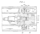
- Fig. 2 is a sectioned side elevation of a fragmentary part of a piston and cylinder assembly corresponding to the embodiment of Fig. 1; and
- Fig. 3 is a schematic illustration of a modified version of the embodiment of Fig. 1.
- The apparatus illustrated schematically in Figures 1 and 3 would be suitable for mounting between a railway car body and a railway truck bolster in essentially the same manner as disclosed in Figure 1 of EP-A-0658466. A
piston assembly 28 of Figures 1 and 3 of this Application divides acylinder 26 into two variable volumehydraulic chambers - In the embodiment of Figure 1, the
chambers fluid flow path 219 which includes two flow restricting orifices 60'' arranged in series. At the junction of the flow restricting orifices 60'' apressure accumulator 64 delivers a predetermined minimum positive pressure to thefluid flow path 219. In parallel with each flow restriction orifice 60'' is a check valve 160'. The orientations of the check valves 160' are mutually opposed, so that fluid flow in thefluid flow path 219 from left to right as illustrated is through the left-hand orifice 60'' and the right-hand check valve 160', and fluid flow from right to left is through the right-hand orifice 60'' and the left-hand check valve 160'. - A shuttle or two-
way check valve 300 communicates between thefluid flow path 219 and thevariable volume chambers centre port 304 of thecheck valve 300 has afluid flow conduit 306 connected thereto whereby thecentre port 304 communicates with an inlet port of apressure relief valve 302. The outlet ofpressure relief valve 302 is connected by aconduit 308 toaccumulator 64 in common with the connection thereto of orifices 60'' and check valves 160'. - The Fig. 1 embodiment operates as follows. When the
piston 28 moves, to the right for example, the volume ofchamber 54 decreases and the volume ofchamber 52 increases. The resulting fluid pressure increase inchamber 54, and the corresponding pressure decrease inchamber 52, actuatesvalve 300 as shown in Fig. 1 so that the increased fluid pressure ofchamber 54 reachesrelief valve 302 viaport 304 andconduit 306. The increased fluid pressure also reaches the corresponding right-hand flow restricting orifice 60'' and check valve 160'. If movement of the piston is slow enough that the resulting pressure differential betweenchambers valve 302, fluid will flow through orifice 60'' on the high pressure side and check valve 160' on the low pressure side until the pressure inchambers accumulator 64. - When the piston movement creates a pressure differential in
chambers valve 302, fluid flows at a greater rate from the high pressure side to the low pressure side through both the orifice 60'' on the high pressure side andvalve 302. Accordingly, the Fig. 1 embodiment provides for normal low velocity relative yawing of a truck with respect to a car body, damping of higher velocity yawing movements, and a bypass circuit with pressure relief valving which limits the maximum restraining force that can be evolved to resist truck-to-car body relative yaw movements. The Fig. 1 embodiment offers the attendant benefit of diminished likelihood of fluid cavitation. - The Fig. 1 schematic structure is embodied in the apparatus of Fig. 2 as a
piston 310 having ahead portion 312 slidably disposed within acylinder 314 to definevariable volume chambers Accumulator 64 is defined by a space within one rod portion ofpiston 310 as described in general terms in EP-A-0658466. - Chambers 52 and 54 communicate via orifices 60'' and check valves 160' with
accumulator 64 viapassages passage 308,chambers pressure relief valve 302.Shuttle check valve 300 has itsport 304 connected to a conduit orpassage 306 for communication with the inlet side ofpressure relief valve 302. - In the Fig. 2 apparatus,
shuttle valve 300 takes the form of aring seal element 320 disposed within anannular groove 322 formed inpiston head 312, thering 320 being so dimensioned with respect togroove 322 as to be slidable longitudinally therein between extreme longitudinal positions. Longitudinal movement ofpiston 310 serves to positionring 320 always in a rearward or trailing position withingroove 322, with respect to the direction of piston movement. The resulting gap at the leading end ofgroove 322 provides a passageway or flow path for controlled fluid flow from thehigher pressure chamber piston head 312 andcylinder 314, aroundseal ring 320, and thence viapassage 306 to the inlet side ofvalve 302.Shuttle check valve 300 operates in the same way with movement ofpiston 310 in either axial direction withincylinder 314. - The orifices 60'' and check valves 160' are combined in a structure comprising a pair of
annular valve plates 324 which are carried adjacent the opposed faces ofpiston head 312 by such suitable means as tension springs (not shown) extending through suitable openings (not shown) inpiston head 312 and connected to therespective plates 324 tourge plates 324 into lightly biased engagement with the respective faces ofpiston head 312. Accordingly, when the force of fluid pressure inpassages 316, which are open toplates 324 preferably at multiple locations about the circumference ofpiston head 312 viaannular grooves 317, exceeds the force of pressure in thecorresponding chamber respective plate 324 toward thepiston head 312, theplate 324 will lift to allow free flow of fluid from therespective groove 317 into therespective chamber valve 302, or a combination of both as above described. - The orifices 60'' are formed as through openings in
plates 324 such that when the fluid pressure in one ofchambers respective plate 324 is maintained by the increased bias of the elevated pressure in engagement with the respective face ofpiston head 312, and fluid flow passes through the orifices 60'' and the corresponding check valve 160' from thehigher pressure chamber - The
valve 302 may be any suitable relief valve assembly, for example a Vickers RV 5-10-5-0-20 relief valve. Thevalve 302 includesthreads 325 by which it is engaged within a stepped,blind bore 326 formed in the piston. A portedvalving portion 328 ofvalve 302 extends withinbore 326 and sealingly engages bore 326 by means of a suitable seal, for example an o-ring seal such as indicated at 330. -
Valving portion 328 includesports 332 on one side ofseal 330 which communicate withpassage 308, and other suitable ports (not shown) on the other side ofseal 330 which communicate withpassage 306. A spring loaded pressure relief valve member (not shown) is disposed withinvalve 302 intermediate the respective ports opening topassages higher pressure chamber shuttle valve 300 andpassages 306 to thelower pressure chamber - A modification of the Fig. 1 embodiment is shown schematically in Fig. 3, the modification being that the orifices 60'' are replaced by a single orifice 60''' disposed in parallel with
pressure relief valve 302 rather than having a flow orifice disposed in parallel with each of the check valves 160'. The function of the Fig. 3 modified embodiment is essentially the same as the Fig. 1 embodiment, except that the flow path of fluid flowing from one ofchambers shuttle valve 300 whereas in the Fig. 1 embodiment the flow orifice flow path bypasses theshuttle valve 300.
Claims (13)
- A fluid flow regulating apparatus for controlling a flow of fluid between a pair of fluid containing spaces (52, 54) which are connected by a fluid flow path (219), said fluid flow regulating apparatus including flow regulating means comprising:restricted flow orifice means (60'') adapted to restrict fluid flow through the fluid flow path (219) between the fluid containing spaces (52, 54);a pair of opposed check valve means (160') disposed in series relationship with each other in the fluid flow path (219) and each being adapted to limit unrestricted fluid flow within the flow regulating means to flow in only one direction; andpressure relief means (302) adapted to relieve the pressure of fluid flow through the fluid flow path (219) between the fluid containing spaces (52, 54) when the pressure differential between the fluid containing spaces (52, 54) exceeds a given pressure;CHARACTERISED IN THAT at least one of the pressure relief means (302) and the restricted flow orifice means (60'') comprises a single fluid control element (302 or 60''') selectively establishing its fluid flow regulating control between respective ones of the pair of fluid containing spaces (52, 54) and the fluid flow path (219).
- Apparatus according to claim 1, wherein the pressure relief means (302) comprises a single pressure relief valve (302) selectively communicating in fluid pressure relief relation between respective ones of the pair of fluid containing spaces (52, 54) and the fluid flow path (219).
- Apparatus according to claim 2, wherein the fluid containing spaces (52, 54) are defined by variable volume chambers (52, 54) on axially opposed sides of a piston (310) which is slidably disposed in a cylinder (314), and the orifice means (60'') and the check valve means 160') of at least one of the flow regulating means consists of an annular member (324) encompassing the piston (310) and being cooperable with portions of the fluid flow path (219) formed in a head portion (312) of the piston (310) to regulate fluid flow within the fluid flow path (219).
- Apparatus according to claim 1, wherein the restricted flow orifice means (60'') comprises a single restricted flow orifice (60''') selectively establishing restricted fluid communication between respected ones of the pair of fluid containing spaces (52, 54) and the fluid flow path (219).
- Apparatus according to claim 4, wherein the flow regulating means comprises a restricted flow orifice (60''') disposed in parallel relationship with the pressure relief valve means (302).
- Apparatus according to any preceding claim, further comprising a two-way check valve (300) which provides hydraulic communication between only the higher pressure one of the two fluid containing spaces (52, 54) and the single pressure control element (302 or 60'''), and blocks hydraulic communication between the lower pressure one of the fluid containing spaces (52, 54) and the single pressure control element (320 or 60''').
- Apparatus according to any preceding claim, wherein the single pressure control element (302 or 60''') selectively establishes its fluid regulating control between respective ones of the pair of fluid containing spaces (52, 54) and the fluid flow path (219) between the pair of check valve means (160').
- Apparatus according to any preceding claim, additionally including fluid pressure accumulator means (64) adapted to communicate with the fluid flow path (219) intermediate the check valve means (160').
- Apparatus according to any preceding claim, wherein the fluid containing spaces (52, 54) are defined by variable volume chambers (52, 54) on axially opposed sides of a piston (310) which is slidably disposed in a cylinder (314), and the flow regulating means is contained wholly within the piston (310) and cylinder (314).
- Apparatus according to claim 9, additionally including fluid pressure accumulator means (64) adapted to communicate with the fluid flow path (219) intermediate the check valve means (160'), the fluid pressure accumulator means (64) being contained wholly within the piston (310).
- Apparatus according to claim 10, wherein the piston (310) comprises a piston head (312) and a pair of elongated rod portions extending coaxially in opposite directions from the piston head (312) and entirely through the respective variable volume chambers (52, 54), and the pressure accumulator means (64) is contained within at least one of the rod portions.
- Apparatus according to any of claims 9 to 11, wherein the pressure relief means (302) comprises a self-contained relief valve assembly (302) which is selectively releasably carried by the piston (310).
- Apparatus for resisting relative rotation between a railway truck and a car body which is supported by the truck and which is relatively rotatable with respect thereto about a generally vertical axis, comprising a fluid flow regulating apparatus according to any preceding claim.
Applications Claiming Priority (2)
| Application Number | Priority Date | Filing Date | Title |
|---|---|---|---|
| US08/469,567 US5662046A (en) | 1993-12-14 | 1995-06-06 | Method and apparatus for controlling railway truck hunting and a railway car body supported thereby |
| US469567 | 1999-12-22 |
Publications (1)
| Publication Number | Publication Date |
|---|---|
| EP0747277A1 true EP0747277A1 (en) | 1996-12-11 |
Family
ID=23864262
Family Applications (1)
| Application Number | Title | Priority Date | Filing Date |
|---|---|---|---|
| EP96304151A Withdrawn EP0747277A1 (en) | 1995-06-06 | 1996-06-05 | Controlling railway truck hunting |
Country Status (3)
| Country | Link |
|---|---|
| US (1) | US5662046A (en) |
| EP (1) | EP0747277A1 (en) |
| CA (1) | CA2172341C (en) |
Cited By (6)
| Publication number | Priority date | Publication date | Assignee | Title |
|---|---|---|---|---|
| EP0893321A1 (en) * | 1997-07-24 | 1999-01-27 | Gec Alsthom Transport Sa | An oleopneumatic anti-roll or anti-yaw suspension device |
| FR2766445A1 (en) * | 1997-07-24 | 1999-01-29 | Gec Alsthom Transport Sa | Oleopneumatic suspension apparatus for road or rail vehicles |
| EP0992415A1 (en) * | 1998-10-07 | 2000-04-12 | Alstom Holdings | Device for damping the transverse motions and the hunting of a vehicle and vehicle equipped with such a device |
| EP1659310A3 (en) * | 2004-11-18 | 2006-11-15 | Öhlins Racing Ab | Damper (shock absorber) intended for vehicles |
| EP3832159A4 (en) * | 2019-04-19 | 2021-12-08 | Crrc Qingdao Sifang Co., Ltd. | METHOD AND APPARATUS FOR CONTROLLING AN ANTILACET SHOCK ABSORBER |
| EP4088051A4 (en) * | 2019-01-11 | 2024-01-17 | Dayco IP Holdings, LLC | Crankcase ventilation system with a flow control device for on board diagnostics |
Families Citing this family (27)
| Publication number | Priority date | Publication date | Assignee | Title |
|---|---|---|---|---|
| DE19922839B4 (en) * | 1999-05-19 | 2004-05-13 | Zf Sachs Ag | vibration |
| DE19922838B4 (en) * | 1999-05-19 | 2004-11-04 | Zf Sachs Ag | vibration |
| US6390278B1 (en) * | 2000-08-29 | 2002-05-21 | Edmund W. Brown | Transfer mechanism for multiple level conveyor |
| US6736245B2 (en) | 2000-08-29 | 2004-05-18 | Topper Industrial, Inc. | Dampening cylinder incorporating stop valve |
| US7070028B2 (en) * | 2001-02-07 | 2006-07-04 | Tenneco Automotive Operating Company Inc. | Frequency dependent damper |
| US6644168B1 (en) * | 2002-08-12 | 2003-11-11 | General Dynamics Armament And Technical Products, Inc. | System and method for active control of recoil mechanism |
| CN102182787A (en) * | 2003-08-27 | 2011-09-14 | 贝尔直升机泰克斯特龙公司 | Dual spring rate damper |
| US8250818B2 (en) * | 2004-03-03 | 2012-08-28 | Robert Tremblay | Self-centering energy dissipative brace apparatus with tensioning elements |
| SE529042C2 (en) * | 2004-12-06 | 2007-04-17 | Oehlins Racing Ab | Telescopic fork |
| US7497448B2 (en) * | 2005-09-09 | 2009-03-03 | Brown Edmund W | Tugger cart with tiltable platform |
| JP4909763B2 (en) * | 2007-02-23 | 2012-04-04 | カヤバ工業株式会社 | Steering damper |
| JP4815454B2 (en) * | 2007-03-14 | 2011-11-16 | カヤバ工業株式会社 | Shock absorber |
| US20120141276A1 (en) * | 2010-12-03 | 2012-06-07 | Zachary Ryan Fuhrer | Frequency-dependent damper and rotary wing system |
| CN103380311B (en) | 2011-02-24 | 2016-01-20 | 贝尔直升机泰克斯特龙公司 | A kind of hot adaptive damping device and there is the aircraft of this hot adaptive damping device |
| JP6000872B2 (en) * | 2013-02-27 | 2016-10-05 | 鹿島建設株式会社 | Control method of hydraulic damper open / close control valve and hydraulic damper used in the method |
| JP5946143B2 (en) * | 2014-02-26 | 2016-07-05 | センクシア株式会社 | Hydraulic damper |
| US9470285B2 (en) * | 2014-04-08 | 2016-10-18 | The Boeing Company | Aircraft door dampening system |
| AU2016233994A1 (en) * | 2015-03-15 | 2017-10-12 | Holmes Solutions Limited Partnership | A fluid circuit device |
| CN107709822A (en) * | 2015-03-15 | 2018-02-16 | 福尔摩斯解决方案合伙有限公司 | Energy transfer device and method of use |
| JP6509641B2 (en) * | 2015-06-17 | 2019-05-08 | 日本車輌製造株式会社 | Body tilting device for railway vehicle |
| FR3040042B1 (en) * | 2015-08-14 | 2018-06-01 | Airbus Helicopters | DAMPING DEVICE, AND AIRCRAFT |
| US20180266104A1 (en) * | 2015-09-15 | 2018-09-20 | The Regents Of The University Of California | Control system and method for mitigating the effects of natural hazards |
| RU174096U1 (en) * | 2017-03-10 | 2017-10-02 | Федеральное государственное бюджетное образовательное учреждение высшего образования "Орловский государственный университет имени И.С. Тургенева" (ФГБОУ ВО "ОГУ имени И.С. Тургенева") | FRICTIONAL OSCILLATOR |
| JP7212552B2 (en) * | 2019-03-04 | 2023-01-25 | Kyb株式会社 | buffer |
| EP3786478A1 (en) * | 2019-09-02 | 2021-03-03 | Öhlins Racing AB | Adjustable bleed valve assembly for shock absorber |
| US12442430B2 (en) * | 2023-04-17 | 2025-10-14 | Advanced Suspension Technology Llc | Damper with base line valve |
| CN117450213A (en) * | 2023-10-17 | 2024-01-26 | 西南交通大学 | An anti-snake damper with high and low dynamic stiffness switchable and its control system |
Citations (3)
| Publication number | Priority date | Publication date | Assignee | Title |
|---|---|---|---|---|
| US3868910A (en) * | 1973-11-26 | 1975-03-04 | Houdaille Industries Inc | Railway car suspension motion control system |
| GB2164305A (en) * | 1983-09-06 | 1986-03-19 | Budd Co | Hydraulic damping means for lateral movements in a railway car |
| EP0243613A1 (en) * | 1986-04-02 | 1987-11-04 | Robert Bosch Gmbh | Device for damping movements |
Family Cites Families (27)
| Publication number | Priority date | Publication date | Assignee | Title |
|---|---|---|---|---|
| US3376831A (en) * | 1965-04-27 | 1968-04-09 | Westinghouse Air Brake Co | Hydraulically dampened car bogie |
| US3719153A (en) * | 1971-01-07 | 1973-03-06 | Krupp Gmbh | Hydraulically dampened car bogie |
| AT349522B (en) * | 1975-04-25 | 1979-04-10 | Plasser Bahnbaumasch Franz | VEHICLE, IN PARTICULAR RAIL VEHICLE |
| US4023689A (en) * | 1975-11-21 | 1977-05-17 | Tarrant Manufacturing Company | Conveyor-type, hydraulic-powered, material-spreading apparatus |
| CA1071026A (en) * | 1976-02-09 | 1980-02-05 | Herbert Scheffel | Railway vehicle suspension |
| US4134343A (en) * | 1976-09-27 | 1979-01-16 | General Steel Industries, Inc. | Radial axle railway truck |
| US4105193A (en) * | 1976-11-26 | 1978-08-08 | General Motors Corporation | Shock absorber and leveling unit with auxiliary damping device for vehicle suspensions |
| US4090723A (en) * | 1977-01-24 | 1978-05-23 | Caterpillar Tractor Co. | Tandem roadwheel leveling system for construction vehicles |
| US4109767A (en) * | 1977-03-04 | 1978-08-29 | Maremont Corporation | Compression head assembly |
| DE2718434C2 (en) * | 1977-04-26 | 1979-06-28 | Fa. Johannes Fuchs, 7257 Ditzingen | Gripper hinged to the boom of a work machine |
| US4262922A (en) * | 1978-03-31 | 1981-04-21 | Nelson Robert D | Boat trailer stabilizing device |
| US4280601A (en) * | 1979-06-21 | 1981-07-28 | Gabriel Of Canada Limited | Shock absorber with improved piston compression valve mechanism |
| US4513899A (en) * | 1982-08-10 | 1985-04-30 | Plessey Incorporated | Stock feeder with adjustable width feed path |
| US4580710A (en) * | 1982-08-10 | 1986-04-08 | Plessey Incorporated | Stock feeder with hydraulic shock absorber |
| NL8500145A (en) * | 1985-01-21 | 1986-08-18 | Koni Bv | HYDRAULIC DOUBLE SHOCK ABSORBER. |
| SE458945B (en) * | 1985-02-18 | 1989-05-22 | Vaexjoe Protes Ab | HYDRAULIC DEVICE, SPECIFICALLY FOR LEG PROTECTION |
| NL8503031A (en) * | 1985-11-05 | 1987-06-01 | Koni Bv | ELECTRICALLY ADJUSTABLE SHOCK ABSORBER. |
| FR2611844B1 (en) * | 1987-03-06 | 1989-07-13 | Bourcier Carbon Christian | PISTON ASSEMBLY FOR HYDRAULIC SHOCK ABSORBER |
| FR2624473B1 (en) * | 1987-12-15 | 1990-05-18 | Aerospatiale | HYDRAULIC DEVICE FOR INDIVIDUAL CONTROL OF THE STEP OF A ROTOR BLADE, AND ROTOR HUB AND ROTOR EQUIPPED WITH SUCH DEVICES |
| NL8800944A (en) * | 1988-04-12 | 1989-11-01 | Koni Bv | MEMORY METAL ADJUSTMENT AND A SHOCK ABSORBER EQUIPPED WITH THIS ADJUSTMENT. |
| DE3817031C2 (en) * | 1988-05-19 | 1994-02-24 | Danfoss As | Steering damper for a kink-controlled vehicle with hydraulic steering |
| DE3837863C2 (en) * | 1988-11-08 | 1995-02-09 | Daimler Benz Ag | Suspension system for vehicles |
| DE3923512A1 (en) * | 1989-07-15 | 1991-01-24 | Stabilus Gmbh | SHOCK VALVE WITH STRONG PROGRESSIVE STEEL CHARACTERISTICS, ESPECIALLY FOR STEERING DAMPERS FOR MOTORCYCLES |
| JPH0726660B2 (en) * | 1990-01-08 | 1995-03-29 | 株式会社クボタ | Hydraulic shock absorber |
| US5347771A (en) * | 1991-06-20 | 1994-09-20 | Kajima Corporation | High damping device for seismic response controlled structure |
| US5271485A (en) * | 1992-09-23 | 1993-12-21 | Predator Systems Inc. | Hydraulic damper |
| DE4328571C1 (en) * | 1993-08-25 | 1994-10-27 | Daimler Benz Ag | Stand for holding a wing in various opening positions relative to its frame |
-
1995
- 1995-06-06 US US08/469,567 patent/US5662046A/en not_active Expired - Fee Related
-
1996
- 1996-03-21 CA CA002172341A patent/CA2172341C/en not_active Expired - Fee Related
- 1996-06-05 EP EP96304151A patent/EP0747277A1/en not_active Withdrawn
Patent Citations (3)
| Publication number | Priority date | Publication date | Assignee | Title |
|---|---|---|---|---|
| US3868910A (en) * | 1973-11-26 | 1975-03-04 | Houdaille Industries Inc | Railway car suspension motion control system |
| GB2164305A (en) * | 1983-09-06 | 1986-03-19 | Budd Co | Hydraulic damping means for lateral movements in a railway car |
| EP0243613A1 (en) * | 1986-04-02 | 1987-11-04 | Robert Bosch Gmbh | Device for damping movements |
Cited By (8)
| Publication number | Priority date | Publication date | Assignee | Title |
|---|---|---|---|---|
| EP0893321A1 (en) * | 1997-07-24 | 1999-01-27 | Gec Alsthom Transport Sa | An oleopneumatic anti-roll or anti-yaw suspension device |
| FR2766445A1 (en) * | 1997-07-24 | 1999-01-29 | Gec Alsthom Transport Sa | Oleopneumatic suspension apparatus for road or rail vehicles |
| EP0992415A1 (en) * | 1998-10-07 | 2000-04-12 | Alstom Holdings | Device for damping the transverse motions and the hunting of a vehicle and vehicle equipped with such a device |
| FR2784341A1 (en) * | 1998-10-07 | 2000-04-14 | Alstom Technology | DEVICE FOR CUSHIONING OF TRANSVERSAL MOVEMENTS AND YOKE OF A VEHICLE, AND VEHICLE PROVIDED WITH SUCH A DEVICE |
| EP1659310A3 (en) * | 2004-11-18 | 2006-11-15 | Öhlins Racing Ab | Damper (shock absorber) intended for vehicles |
| US7607522B2 (en) | 2004-11-18 | 2009-10-27 | öHLINS RACING AB | Shock absorber for vehicles |
| EP4088051A4 (en) * | 2019-01-11 | 2024-01-17 | Dayco IP Holdings, LLC | Crankcase ventilation system with a flow control device for on board diagnostics |
| EP3832159A4 (en) * | 2019-04-19 | 2021-12-08 | Crrc Qingdao Sifang Co., Ltd. | METHOD AND APPARATUS FOR CONTROLLING AN ANTILACET SHOCK ABSORBER |
Also Published As
| Publication number | Publication date |
|---|---|
| CA2172341C (en) | 1999-11-02 |
| US5662046A (en) | 1997-09-02 |
| CA2172341A1 (en) | 1996-12-07 |
Similar Documents
| Publication | Publication Date | Title |
|---|---|---|
| EP0747277A1 (en) | Controlling railway truck hunting | |
| DE10020778B4 (en) | Hydraulic shock absorber with damping force control | |
| KR100451289B1 (en) | Damping force adjustable hydraulic buffer | |
| US4786034A (en) | Apparatus for damping courses of movement | |
| US5024302A (en) | Apparatus for damping courses of motion | |
| DE3902312C2 (en) | ||
| US5730260A (en) | Shock absorber | |
| US5404973A (en) | Damping force control type hydraulic shock absorber | |
| US3483952A (en) | Two-way hydraulic unit | |
| DE19512437A1 (en) | Device for compensating the lateral force acting on a rail vehicle | |
| WO2008097183A1 (en) | Shock absorber with hydraulic flow ducts | |
| DE69116515T2 (en) | Hydromechanical control | |
| US5868161A (en) | Damper valve | |
| US3868910A (en) | Railway car suspension motion control system | |
| JP4478848B2 (en) | Damping force adjustable hydraulic shock absorber | |
| US6616124B2 (en) | Spool valve for controlled dampers | |
| CA2136379C (en) | Method and apparatus for controlling railway truck hunting and a railway car body supported thereby | |
| US7261030B2 (en) | Method and system for improving stability of hydraulic systems with load sense | |
| US4480555A (en) | Double acting railway car stabilizing cylinder | |
| US4359247A (en) | Brake for rail vehicles | |
| JPH1182603A (en) | Variable damping force damper and vehicle damping device | |
| AU688672B2 (en) | Method and apparatus for controlling railway truck hunting and a railway car body supported thereby | |
| JPH09222146A (en) | Damping force adjustable hydraulic shock absorber | |
| JP2000283210A (en) | Hydraulic shock absorber | |
| KR102920842B1 (en) | Hydraulic Suspension System of a Vehicle Including a Pressure-Controlled Hydraulic Control Assembly |
Legal Events
| Date | Code | Title | Description |
|---|---|---|---|
| PUAI | Public reference made under article 153(3) epc to a published international application that has entered the european phase |
Free format text: ORIGINAL CODE: 0009012 |
|
| AK | Designated contracting states |
Kind code of ref document: A1 Designated state(s): BE DE DK ES FR GB IT NL SE |
|
| 17P | Request for examination filed |
Effective date: 19970404 |
|
| 17Q | First examination report despatched |
Effective date: 19981023 |
|
| GRAG | Despatch of communication of intention to grant |
Free format text: ORIGINAL CODE: EPIDOS AGRA |
|
| STAA | Information on the status of an ep patent application or granted ep patent |
Free format text: STATUS: THE APPLICATION HAS BEEN WITHDRAWN |
|
| 18W | Application withdrawn |
Withdrawal date: 19990615 |