EP0747221A2 - Ink jet head, ink jet apparatus and ink jet recording method - Google Patents
Ink jet head, ink jet apparatus and ink jet recording method Download PDFInfo
- Publication number
- EP0747221A2 EP0747221A2 EP96109037A EP96109037A EP0747221A2 EP 0747221 A2 EP0747221 A2 EP 0747221A2 EP 96109037 A EP96109037 A EP 96109037A EP 96109037 A EP96109037 A EP 96109037A EP 0747221 A2 EP0747221 A2 EP 0747221A2
- Authority
- EP
- European Patent Office
- Prior art keywords
- ink
- heat generating
- ink jet
- generating resistors
- ejection outlet
- Prior art date
- Legal status (The legal status is an assumption and is not a legal conclusion. Google has not performed a legal analysis and makes no representation as to the accuracy of the status listed.)
- Granted
Links
Images


Classifications
-
- B—PERFORMING OPERATIONS; TRANSPORTING
- B41—PRINTING; LINING MACHINES; TYPEWRITERS; STAMPS
- B41J—TYPEWRITERS; SELECTIVE PRINTING MECHANISMS, i.e. MECHANISMS PRINTING OTHERWISE THAN FROM A FORME; CORRECTION OF TYPOGRAPHICAL ERRORS
- B41J2/00—Typewriters or selective printing mechanisms characterised by the printing or marking process for which they are designed
- B41J2/005—Typewriters or selective printing mechanisms characterised by the printing or marking process for which they are designed characterised by bringing liquid or particles selectively into contact with a printing material
- B41J2/01—Ink jet
- B41J2/015—Ink jet characterised by the jet generation process
- B41J2/04—Ink jet characterised by the jet generation process generating single droplets or particles on demand
- B41J2/045—Ink jet characterised by the jet generation process generating single droplets or particles on demand by pressure, e.g. electromechanical transducers
- B41J2/04501—Control methods or devices therefor, e.g. driver circuits, control circuits
- B41J2/04533—Control methods or devices therefor, e.g. driver circuits, control circuits controlling a head having several actuators per chamber
-
- B—PERFORMING OPERATIONS; TRANSPORTING
- B41—PRINTING; LINING MACHINES; TYPEWRITERS; STAMPS
- B41J—TYPEWRITERS; SELECTIVE PRINTING MECHANISMS, i.e. MECHANISMS PRINTING OTHERWISE THAN FROM A FORME; CORRECTION OF TYPOGRAPHICAL ERRORS
- B41J2/00—Typewriters or selective printing mechanisms characterised by the printing or marking process for which they are designed
- B41J2/005—Typewriters or selective printing mechanisms characterised by the printing or marking process for which they are designed characterised by bringing liquid or particles selectively into contact with a printing material
- B41J2/01—Ink jet
- B41J2/015—Ink jet characterised by the jet generation process
- B41J2/04—Ink jet characterised by the jet generation process generating single droplets or particles on demand
- B41J2/045—Ink jet characterised by the jet generation process generating single droplets or particles on demand by pressure, e.g. electromechanical transducers
- B41J2/04501—Control methods or devices therefor, e.g. driver circuits, control circuits
- B41J2/04563—Control methods or devices therefor, e.g. driver circuits, control circuits detecting head temperature; Ink temperature
-
- B—PERFORMING OPERATIONS; TRANSPORTING
- B41—PRINTING; LINING MACHINES; TYPEWRITERS; STAMPS
- B41J—TYPEWRITERS; SELECTIVE PRINTING MECHANISMS, i.e. MECHANISMS PRINTING OTHERWISE THAN FROM A FORME; CORRECTION OF TYPOGRAPHICAL ERRORS
- B41J2/00—Typewriters or selective printing mechanisms characterised by the printing or marking process for which they are designed
- B41J2/005—Typewriters or selective printing mechanisms characterised by the printing or marking process for which they are designed characterised by bringing liquid or particles selectively into contact with a printing material
- B41J2/01—Ink jet
- B41J2/015—Ink jet characterised by the jet generation process
- B41J2/04—Ink jet characterised by the jet generation process generating single droplets or particles on demand
- B41J2/045—Ink jet characterised by the jet generation process generating single droplets or particles on demand by pressure, e.g. electromechanical transducers
- B41J2/04501—Control methods or devices therefor, e.g. driver circuits, control circuits
- B41J2/0458—Control methods or devices therefor, e.g. driver circuits, control circuits controlling heads based on heating elements forming bubbles
-
- B—PERFORMING OPERATIONS; TRANSPORTING
- B41—PRINTING; LINING MACHINES; TYPEWRITERS; STAMPS
- B41J—TYPEWRITERS; SELECTIVE PRINTING MECHANISMS, i.e. MECHANISMS PRINTING OTHERWISE THAN FROM A FORME; CORRECTION OF TYPOGRAPHICAL ERRORS
- B41J2/00—Typewriters or selective printing mechanisms characterised by the printing or marking process for which they are designed
- B41J2/005—Typewriters or selective printing mechanisms characterised by the printing or marking process for which they are designed characterised by bringing liquid or particles selectively into contact with a printing material
- B41J2/01—Ink jet
- B41J2/135—Nozzles
- B41J2/14—Structure thereof only for on-demand ink jet heads
- B41J2/14016—Structure of bubble jet print heads
- B41J2/14032—Structure of the pressure chamber
- B41J2/14056—Plural heating elements per ink chamber
-
- B—PERFORMING OPERATIONS; TRANSPORTING
- B41—PRINTING; LINING MACHINES; TYPEWRITERS; STAMPS
- B41J—TYPEWRITERS; SELECTIVE PRINTING MECHANISMS, i.e. MECHANISMS PRINTING OTHERWISE THAN FROM A FORME; CORRECTION OF TYPOGRAPHICAL ERRORS
- B41J2/00—Typewriters or selective printing mechanisms characterised by the printing or marking process for which they are designed
- B41J2/005—Typewriters or selective printing mechanisms characterised by the printing or marking process for which they are designed characterised by bringing liquid or particles selectively into contact with a printing material
- B41J2/01—Ink jet
- B41J2/135—Nozzles
- B41J2/14—Structure thereof only for on-demand ink jet heads
- B41J2/14016—Structure of bubble jet print heads
- B41J2/14072—Electrical connections, e.g. details on electrodes, connecting the chip to the outside...
Definitions
- the present invention was made to solve the above described problems related to the conventional methods, and its primary object is to provide an ink jet recording head and ink jet apparatus, which are provided with gradation control functions, being thereby enabled to excel in recording quality, and an ink jet recording method for effecting superior gradation.
- Figure 10 is a schematic drawing showing the heat generating resistor arrangement in this second embodiment.
- the present invention is usable with any ink jet system.
- an ink jet head or an ink jet apparatus employing an ink jet system of a particular type in which thermal energy is used to form flying liquid droplets which effect images the most preferable effects can be obtained.
Landscapes
- Particle Formation And Scattering Control In Inkjet Printers (AREA)
- Ink Jet (AREA)
Abstract
Description
- The present invention relates to an ink jet head which ejects ink toward a recording medium in response to driving signals, and an ink jet apparatus which records characters images, pictures images, and/or the like, on the recording medium by employing the ink jet head. It also relates to an ink jet recording method for recording images with gradation by driving a plurality of heat generating resistors.
- The ink jet apparatus does not generate noise, can record at a high speed, and can easily record color images; therefore, it has come to be widely used as a means for recording images on a recording medium such as a sheet of paper, in various apparatuses, for example, a word processor, a facsimile apparatus, a copying apparatus, or a printer.
- The ink jet head is mounted in an ink jet apparatus, as a member which records character images, picture images and/or the like, on the recording medium by ejecting ink from the ink jet portions in response to driving signal input from the ink jet apparatus. More specifically, the ink jet head ejects ink using the thermal energy generated in response to the driving signals from the ink jet apparatus.
- Figure 8 is a schematic perspective view of an ink jet head, and Figure 9 is a schematic section of the same ink jet head.
- A
reference numeral 40 designates an ejection orifice from which the ink is ejected; 41, a first substrate; 41a, a heat generating resistor disposed on thefirst substrate 41 in order to generate a bubble in the ink by heating the ink; 42, a second substrate; 42a, an ink path; 42b, an ink chamber; and 42c designates an ink supply port. - As is evident from the drawing, the
first substrate 41 and thesecond substrate 42 are joined to form theink path 42a and theink chamber 42b. The ink is supplied through theink supply port 42c, and is delivered to theink chamber 42b, and then to theink path 42a. The heat generatingresistor 41a provided within theink path 42a generates heat in response to the driving signals sent from the driving signal supplying means of the ink jet apparatus. The heat generates a bubble in the ink within the ink path, and as the bubble develops, the ink within theink path 42a is ejected toward the recording medium from theejection orifice 40. - Incidentally, as the ink jet apparatus has recently come to be employed in a printer or the like to output picture images or the like, much higher picture quality has come to be demanded. As for conventional means for improving picture quality, there are methods in which density gradation is controlled by controlling the size of the ink droplet.
- According to one such method, which is disclosed in Japanese Laid-Open Patent Application No. 132,259/1980, the density gradation of the ink jet is controlled by changing the amount of the ink ejected per picture element. More specifically, a plurality of heat generating resistors are disposed in a single liquid path, and the driving signals are selectively supplied to each heat generating resistor to change the amount of the ink ejected per picture element. The above publication discloses a structure in which two heat generating resistors are arranged in series in the direction in which the ink is ejected, and another structure which two heat generating resistors are arranged in parallel relative to the direction in which the ink is ejected.
- However, the conventional methods have the following problems.
- First, the structure in which the plurality of heat generating resistors in the same liquid path are arranged in series in the ink ejecting direction, will be described. When the configuration (area size) of one heat generating resistor is the same as the other, there is a difference in the location of the center of gravity, that is, the heat generating center, of each heat generating resistor, between when only one of the heat generating resistors is driven and when both of them are driven at the same time; therefore, the nozzle length must be extended. This problem can be solved by shortening the length (in the ink ejecting direction) of the heat generating resistor on the ejection orifice side. However, the change in the length of the heat generating resistor requires the change in the voltage to be applied to the heat generating resistor. In other words, when the length of the heat generating resistor on the ejection orifice side is shortened, the voltage to be applied to one heat generating resistor has to be substantially differentiated from the voltage to be applied to the other. As a result, there must be as many power sources as heat generating resistors.
- Next, the structure in which the two heat generating resistors in the same flow path are arranged in parallel relative to the ejection direction will be described. When the center of gravity of the heat generating resistor is optimally adjusted to agree with a condition in which only one heat generating resistor is driven, the bubble generating power obtainable when both heat generating resistor are driven at the same time becomes too large, scattering the ink droplets. On the contrary, when the center of gravity of the heat generating resistor is optimally adjusted to agree with a condition in which two heat generating resistors are driven at the same time, the bubble generating power obtainable when the ink is to be ejected by driving only one heat generating resistor is liable to become insufficient to eject the ink as the ink droplet. In other words, when the heat generating resistors are arranged in parallel relative to the liquid ejecting direction, satisfactory picture quality cannot be obtained whether two heat generating resistors are driven at the same time or only one heat generating resistor is driven.
- The present invention was made to solve the above described problems related to the conventional methods, and its primary object is to provide an ink jet recording head and ink jet apparatus, which are provided with gradation control functions, being thereby enabled to excel in recording quality, and an ink jet recording method for effecting superior gradation.
- The inventors of the present invention disclosed in this patent application made the following discoveries as the result of extensive studies of the problems described above; when the plurality of heat generating resistors within the ink flow path are arranged in parallel relative to the ejection direction, and the location of the center of gravity, that is, the heat generating center, of each heat generating resistor is differentiated from those of the others in the ejecting direction, more specifically, when the center of gravity, that is, the heat generating center, of the heat generating resistor is shifted so that the heat generating resistor which forms a smaller dot when driven alone can be displaced toward the ejection orifice side, the aforementioned problems can be solved.
- Thus, the present invention proposes an ink jet head comprising ink ejection outlet for ejecting ink, a plurality of heat generating resistors for generating thermal energy contributable to ejecting the ink, and ink flow path comprising the plurality of the heat generating resistors and being in fluid communication with the ejection outlet, the heat generating resistors generating the thermal energy upon receiving a driving signal, so that a bubble is generated in the ink within the ink flow path to eject the ink through the ink ejection outlet; wherein the plurality of the heat generating resistors are arranged in parallel, relative to the ink ejecting direction, in the ink flow path, and the distances from the heat generating centers of the heat generating resistors to the ejection outlet are different.
- Further, the present invention proposes an ink jet apparatus comprising: an ink jet head comprising ink ejection outlet for ejecting ink, a plurality of heat generating resistors for generating thermal energy contributable to ejecting the ink, and ink flow path comprising the plurality of the heat generating resistors and being in fluid communication with the ejection outlet, the heat generating resistors generating the thermal energy upon receiving a driving signal, so that a bubble is generated in the ink within the ink flow path to eject the ink through the ink ejection outlet; and signal supplying means for supplying the driving signal to the ink jet head; wherein the plurality of the heat generating resistors are arranged in parallel, relative to the ink ejecting direction, in the ink flow path, and the distances from the heat generating centers of the heat generating resistors to the ejection outlet are different.
- Further, the present invention proposes an ink jet recording method for recording images with gradation using an ink jet head comprising ink ejection outlet for ejecting ink, a plurality of heat generating resistors for generating thermal energy contributable to ejecting the ink, and ink flow path comprising the plurality of the heat generating resistors and being in fluid communication with the ejection outlet, the heat generating resistors generating the thermal energy upon receiving a driving signal, so that a bubble is generated in the ink within the ink flow path to eject the ink through the ink ejection outlet; wherein the plurality of the heat generating resistors are arranged in parallel, relative to the ink ejecting direction, in the ink flow path, and the distances from the heat generating centers of heat generating resistors to the ejection outlet are different; and when the heat generating resistor disposed closest to the ejection outlet, among the plurality of the heat generating resistors, is driven alone, an ink droplet with the smallest volume is ejected.
- With the provision of tee above described structure, even when a plurality of heat generating resistors with various area sizes are disposed within a single ink flow path, the ink can be stably ejected in any driving mode; therefore, the amount of the ink to be injected per picture element can be reliably varied, enabling to accomplish high quality gradation.
- Further, gradation can be controlled without increasing the number of data pads; without increase in the number of the pads, contact reliability is improved. Therefore, it is possible to provide an ink jet head and an ink jet apparatus, which are capable of accomplishing stable gradation, and thereby realizing superior print quality.
- These and other objects, features and advantages of the present invention will become more apparent upon a consideration of the following description of the preferred embodiments of the present invention taken in conjunction with the accompanying drawings.
- Figure 1 is a schematic drawing showing the heat generating resistor arrangement in the first embodiment of the present invention.
- Figure 2 is a schematic drawing showing the driving portion in the first embodiment of the present invention.
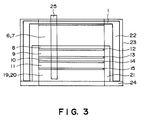
- Figure 3 is a schematic drawing showing the driving portion arrangement on the substrate in the first embodiment of the present invention.
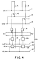
- Figure 4 is an equivalent circuit for driving the heat generating resistor in the first embodiment of the present invention.
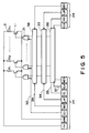
- Figure 5 is also an equivalent circuit for driving the heat generating resistor in the first embodiment of the present invention.
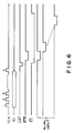
- Figure 6 is a timing chart for driving the head in the first embodiment of the present invention.
- Figure 7 is a perspective view of an ink jet apparatus in which the ink jet head in accordance with the present invention can be mounted.
- Figure 8 is a schematic perspective view of a conventional ink jet head.
- Figure 9 is a schematic section of the conventional ink jet head.
- Figure 10 is a schematic drawing showing the heat generating resistor arrangement in the second embodiment of the present invention.
- The ink jet head and the ink jet apparatus in accordance with the present invention will be described with reference to the drawings.
- The ink jet heads in the following embodiments of the present invention comprise a structure similar to that of the aforementioned conventional ink jet head; heat is generated by the heat generating resistor driven by the driving signals supplied from the driving signal supplying means of the ink jet apparatus to the ink jet head, and the generated heat causes the ink within the ink flow path to bubble, which in turn causes the ink within the ink path to be ejected toward the recording medium from the ejection orifice (ink ejection orifice) disposed so as to face the recording medium, effecting the character image, the picture images, and/or the like.
- Further, the ink jet heads in the following embodiments are characterized in that each ink flow path is provided with a plurality of heat generating resistors so that control can be executed to accomplish high quality.
- Next, the characteristic structures of the present invention, and the effects thereof, will be described in detail in the following embodiments.
- Figure 1 is a schematic drawing showing the ink jet head arrangement on the substrate of the ink jet head in the first embodiment of the present invention, and Figure 2 is a schematic drawing showing the electrical wiring for the heat generating resistor in the first embodiment.
- Within each ejection ink flow path formed between the adjacent ink
flow path walls 5, two heat generating resistors, that is, a firstheat generating resistor 3 and a secondheat generating resistor 4, are disposed, wherein the distance from one heat generating resistor to theejection orifice 40 is differentiated from the distance from the other heat generating resistor to theejection orifice 40. The heat generatingresistors common wiring 1 located under the insulation layer, that is, the layer directly below the heat generating resistor, and voltage is applied to the heat generatingresistors common wiring 1. -
Wirings heat generating resistor 3 and the secondheat generating resistor 4, and switchingtransistors holes 16, respectively. The switching transistors are also disposed under the insulation film, that is, the layer directly below the heat generating resistor.Signal wirings transistors transistors latch circuits - With the above structure in place, data for driving the heat generating resistor are picked up by the shift register-
latch circuits transistors ground wirings switching transistors - Figure 13 is a schematic drawing depicting the general structure of the substrate in the first embodiment.
- A
substrate 23 comprises a plurality of consecutively disposedcells 25 constituting thecommon wiring 1 illustrated in Figures 1 and 2. Thecommon wiring 1 is connected to contact 24, commonvertical wiring 23, receiving power from an external power source. The ground wirings 12, 13, 14 and 15 are connected to thecontact 24 by way of thevertical ground wiring 21. - A circuit diagram equivalent to the structures illustrated in Figures 1, 2 and 3 is shown in Figures 4 and 5.
- In Figure 4, the shift register-
latch circuits shift register 36, aclock signal line 37 and aserial data line 35 are connected, and the data are transferred to theshift register 36 in response to the clock signal. The data inputted into theshift register 36 are retained by thelatch 33 in response to the latch signal sent through thelatch signal line 34. An enablesignal line 32 is connected to an ANDgate 31 to input the timing signal for applying the data retained in thelatch 33 to thetransistor 11. Since there are two enablesignal lines 32, theheat generating resistors - Figure 5 is a circuit diagram equivalent to the general structure of the
substrate 23 on which the plurality of the cells illustrated in Figure 4 are consecutively disposed. - A
decoder 38 and adecoder signal line 39, which are illustrated in Figure 5, are for varying the driving timing, and are not provided with a plurality of theenable signal lines 32, being enabled to drive the heat generating resistor with various timings, without the need for a large number of contacts. The basic timing chart for the structure is given in Figure 6. - Next, the control to be executed to stabilize the ink ejection, in terms of amount, by using the
substrate 23 will be described. - The ink flow path confined between the adjacent ink flow path walls is filled with the ink which is heated by the first and second
heat generating resistors ejection orifice 40 due to the pressure generated by the development of the bubble. - In this embodiment, the
heat generating resistors heat generating resistor 4 for forming the smaller dot is disposed closer to the ejection orifice than the firstheat generating resistor 3. In addition, the secondheat generating resistor 4 has a smaller area size than the firstheat generating resistor 3. The employment of this structure can reduce the amount of the ink between the secondheat generating resistor 4 and the ejection orifice. Therefore, even when only the secondheat generating resistor 4 is driven to produce an ink droplet which effects the smaller dot, the ejection failure or the like, which occurs due to unavailability of a sufficient amount of the bubble generation power, is not liable to occur. Further, the center of gravity, that is, the heat generating center, of the firstheat generating resistor 3 is disposed more rearward (on the ink supply port side) than the center of gravity, that is, the heat generating center of the secondheat generating resistor 4. Therefore, even when the secondheat generating resistor 4 and the firstheat generating resistor 3 are driven at the same time to form an ink droplet which effects a larger dot, the ink is not liable to be scattered by an excessive supply of the bubble generation power. Incidentally, the location of the integral center of gravity of the secondheat generating resistor 4 and the firstheat generating resistor 3 is determined by how the secondheat generating resistor 4 and the firstheat generating resistor 3 are arranged. For the sake of convenience, the distance from the secondheat generating resistor 4 to the edge of the ejection orifice may be set to be half the distance between the firstheat generating resistor 3 to the edge of the ejection orifice. This is because in a recent ink jet head in which the ink flow paths are disposed in high density, the size of the secondheat generating resistor 4 which is disposed closer to the ejection orifice must be rendered relatively larger, whereas it is impossible to increase the size of the firstheat generating resistor 3 too excessively relative to the size of the secondheat generating resistor 4. - As for the method for forming a larger dot, there are other methods beside the aforementioned one. For example, the larger dot can be also formed by driving only the first
heat generating resistor 3. Further, three levels of gradation can be effected by driving only the secondheat generating resistor 4, by driving only the firstheat generating resistor 3, or by driving both the first and the secondheat generating resistors - When images were recorded using the ink jet head in accordance with this embodiment, preferable ejection was maintained for both the smaller dots and the larger dots, accomplishing high quality in terms of gradation.
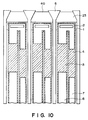
- When images were recorded with two levels of gradation using the ink jet head described in the first embodiment, the ink sometimes failed to be preferably ejected due to insufficiency in the bubble generation power. This phenomenon was related to the physical properties of the ink. Therefore, in this embodiment, the area size of the heat generating resistor closer to the ejection orifice, which is to be driven alone, is rendered larger than that of the heat generating resistor closer to the supply port in order to solve the above problem.
- Figure 10 is a schematic drawing showing the heat generating resistor arrangement in this second embodiment.
- In this embodiment, the locations of the first and the second
heat generating resistors - Further, in this embodiment, the only requirement is for the heat generating resistor closer to the ejection orifice to have a sufficiently large area size. In other words, it is not mandatory for the heat generating resistor closer to the supply port to be rendered smaller than the heat generating resistor closer to the ejection orifice. Therefore, when sufficient space is available in the ink flow path, two heat generating resistors may be given an equal area size.
- When the ink jet head in this embodiment was subjected to a printing test, the ink was preferably ejected for both the smaller and the larger dots, accomplishing high quality in terms of gradation.
- In the preceding embodiments, the present invention was described with reference to the ink jet head in which two heat generating resistors were disposed in a single ink flow path, but it is obvious that the present invention is also applicable to a head in which three or more heat generating resistors are disposed in a single ink flow path.
- Next, the ink jet head in accordance with the present invention, and the ink jet apparatus compatible with such an ink jet head, will be described in more detail.
- The present invention is usable with any ink jet system. However, when it is applied to an ink jet head or an ink jet apparatus employing an ink jet system of a particular type in which thermal energy is used to form flying liquid droplets which effect images, the most preferable effects can be obtained.
- The typical structure and the operational principle are preferably the ones disclosed in U.S. Patent Nos. 4,723,129 and 4,740,796. It is preferable that the present invention be used in conjunction with the principles disclosed in these documents.
- Next, the aforementioned ink jet system will be concisely described.
- The heat generating resistor is disposed so as to face a sheet or an ink flow path in which liquid (ink) is held. The thermal energy for triggering the film boiling phenomenon at the interface between the heat generating resistor and the liquid is generated with the application of at least one driving signal which is correspondent to recording data, and is capable of increasing the liquid temperature to the film boiling point above the nucleation boiling point. Since this system can form bubbles in the liquid (ink), one bubble for one driving signal, in response to the driving signals applied to the heat generating resistor, it is particularly suitable for an on-demand type recording method. The development and contraction of the bubble forms at least one liquid droplet while ejecting the liquid from the ejection orifice. The driving signal is preferred to be in the form of a pulse signal since a pulse signal, which can instantly generate bubbles, and also can allow the bubbles to instantly contract, can eject the ink with preferable response. As for the types of the driving signal in a pulse form, those disclosed in U.S. Patents Nos. 4,463,359 and 4,345,262 are preferable. In addition, the temperature increasing rate of the heating surface is preferably such as disclosed in U.S. Patent No. 4,313,124.
- The structure of the ink jet head may be as shown in U.S. Patent Nos. 4,558,333 and 4,459,600 wherein the heating portion is disposed at a bent portion, as well as the structure of the combination of the ejection outlet, liquid passage and the electrothermal transducer as disclosed in the above-mentioned patents. In addition, the present invention is applicable to the structure disclosed in Japanese Laid-Open Patent Application No. 138461/1984 wherein an opening for absorbing pressure wave of the thermal energy is formed corresponding to the ejecting orifice.
- The present invention is effectively applicable to a so-called full-line type ink jet head having a length corresponding to the maximum recording width. Such an ink jet head may comprise a single ink jet head and plural ink jet head combined to cover the maximum width.
- In addition, the present invention is applicable to a replaceable chip type ink jet head which is connected electrically with the main apparatus and can be supplied with the ink when it is mounted in the main assembly, or to a cartridge type ink jet head having an integral ink container.
- The provisions of the recovery means and/or the auxiliary means for the preliminary operation are preferable, because they can further stabilize the effects of the present invention. As for such means, there are preliminary heating means which may be the heat generating resistor, an additional heating element, or a combination thereof. Also, means for effecting preliminary ejection (not for the recording operation) can stabilize the recording operation.
- The present invention is effectively applicable to an apparatus having at least one of a monochromatic mode mainly with black, a multi-color mode with different color ink materials and/or a full-color mode using the mixture of the colors, which may be an integrally formed recording unit or a combination of plural recording heads.
- Furthermore, in the foregoing embodiment, the ink has been liquid. It may be, however, an ink material which is solidified below room temperature but liquefied at room temperature. Since the ink is controlled within the temperature not lower than 30°C and not higher than 70°C to stabilize the viscosity of the ink to provide the stabilized ejection in a usual recording apparatus of this type, the ink may be such that it is liquefied as the recording signal is applied. In addition, the temperature rise which occurs to the head due to the thermal energy, or the excessive temperature rise of the ink, can be positively prevented by consuming it for the state change of the ink from the solid state to the liquid State. Further, the ink which solidifies when unattended may be employed to solve the problem related to ink evaporation. In other words, the present invention is also compatible with the ink which can be liquefied, being thereby ejected in liquid state, by the application of the recording signal, and begins solidifying by the time it reaches the recording medium. Such an ink material may be retained as a liquid or solid material in through holes or recesses formed in a porous sheet as disclosed in Japanese Laid-Open Patent Application No. 56,847/1979 and Japanese Laid-Open Patent Application No. 71,260/1985. The sheet is faced to the heat generating resistor.
- The most effective system for the ink materials described above is the film boiling system.
- The application of the ink jet head and the ink jet apparatus in accordance with the present invention is not limited to a printer; they may be also applied to a textile printing apparatus which ejects ink for the purpose of dyeing, a pen plotter, or the like.
- Figure 7 is a perspective view of an example of an ink jet apparatus (IJA) in which the ink jet head in accordance with the present invention is installed as a part of an ink jet head cartridge (IJC).
- In the drawing, a
reference numeral 20 designates an ink jet head cartridge (IJC) comprising a group of ink flow paths from which ink is ejected onto the recording surface of the recording sheet as the recording medium delivered onto aplaten 24. Areference numeral 16 designates a carriage (HC) which holds theIJC 20. Thecarriage 16 is connected to a part of a drivingbelt 18 which transmits the driving force from the a drivingmotor 17, and is set across twoguide shafts IJC 20 can be reciprocally moved across the entire width of the recording sheet. - A
reference numeral 26 designates a head performance recovery apparatus. It is disposed adjacent to one end of the moving path of theIJC 20, for example, at a location correspondent to the home position. TheIJC 20 is capped with a cap by a driving force transmitted from amotor 22 through atransmission mechanism 23. TheIJC 20 is capped at the end of a recording operation or the like so that the IJC can be protected. - A
reference numeral 30 designates a blade as a wiping member formed of silicone rubber. The wipingmember 30 is disposed on one of the side walls of the headperformance recovery apparatus 26, being extended like a cantilever by a blade holding member 30a. It is moved also by themotor 22 and thetransmission mechanism 23 as is the headperformance recovery apparatus 26, and is enabled to come in contact with the liquid ejection surface of theIJC 20. With the provision of the above structure, theblade 30 is extended into the moving path of theIJC 20, with a proper timing synchronized with the recording movement of the IJC, or after an ejection performance recovery operation carried out by the heatperformance recovery apparatus 26, so that liquid such as residual ejection liquid or dew formed on the ejection orifice surface due to condensation, dust, or the like, is wiped away as theIJC 20 moves. - While the invention has been described with reference to the structures disclosed herein, it is not confined to the details set forth and this application is intended to cover such modifications or changes as may come within the purposes of the improvements or the scope of the following claims.
- An ink jet head includes ink ejection outlet for ejecting ink, a plurality of heat generating resistors for generating thermal energy contributable to ejecting the ink, and ink flow path comprising the plurality of the heat generating resistors and being in fluid communication with the ejection outlet, the heat generating resistors generating the thermal energy upon receiving a driving signal, so that a bubble is generated in the ink within the ink flow path to eject the ink through the ink ejection outlet; wherein the plurality of the heat generating resistors are arranged in parallel, relative to the ink ejecting direction, in the ink flow path, and the distances from the heat generating centers of the heat generating resistors to the ejection outlet are different.
Claims (17)
- An ink jet head comprising ink ejection outlet for ejecting ink, a plurality of heat generating resistors for generating thermal energy contributable to ejecting the ink, and ink flow oath comprising said plurality of the heat generating resistors and being in fluid communication with said ejection outlet, said heat generating resistors generating the thermal energy upon receiving a driving signal, so that a bubble is generated in the ink within said ink flow path to eject the ink through said ink ejection outlet;
wherein said plurality of the heat generating resistors are arranged in parallel, relative to the ink ejecting direction, in the ink flow path, and the distances from the heat generating centers of said heat generating resistors to said ejection outlet are different. - An ink jet head according to Claim 1, wherein said heat generating resistors are different from each other in the surface area with which the ink is heated.
- An ink jet head according to Claim 1, wherein said heat generating resistors are separately drivable.
- An ink jet head according to Claim 2, wherein among said heat generating resistors, those with a smaller heating surface are disposed closer to said ejection outlet.
- An ink jet head according to Claim 2, wherein among said heat generating resistors, those with a larger heating surface are disposed closer to said ejection outlet.
- An ink jet apparatus comprising:an ink jet head comprising ink ejection outlet for ejecting ink, a plurality of heat generating resistors for generating thermal energy contributable to ejecting the ink, and ink flow path comprising said plurality of the heat generating resistors and being in fluid communication with said ejection outlet, said heat generating resistors generating the thermal energy upon receiving a driving signal, so that a bubble is generated in the ink within said ink flow path to eject the ink through said ink ejection outlet; andsignal supplying means for supplying said driving signal to said ink jet head;wherein said plurality of the heat generating resistors are arranged in parallel, relative to the ink ejecting direction, in the ink flow path, and the distances from the heat generating centers of said heat generating resistors to said ejection outlet are different.
- An ink jet apparatus according to Claim 7, wherein said heat generating resistors are different from each other in the surface area with which the ink is heated.
- An ink jet apparatus according to Claim 7, wherein said heat generating resistors are separately drivable.
- An ink jet apparatus according to Claim 9, wherein among said heat generating resistors, those with a smaller heating surface are disposed closer to said ejection outlet.
- An ink jet apparatus according to Claim 9, wherein among said heat generating resistors, those with a larger heating surface are disposed closer to said ejection outlet.
- An ink jet recording method for recording images with gradation using an ink jet head comprising ink ejection outlet for ejecting ink, a plurality of heat generating resistors for generating thermal energy contributable to ejecting the ink, and ink flow path comprising said plurality of the heat generating resistors and being in fluid communication with said ejection outlet, said heat generating resistors generating the thermal energy upon receiving a driving signal, so that a bubble is generated in the ink within said ink flow path to eject the ink through said ink ejection outlet;
wherein said plurality of the heat generating resistors are arranged in parallel, relative to the ink ejecting direction, in the ink flow path, and the distances from the heat generating centers of heat generating resistors to said ejection outlet are different, and
when the heat generating resistor disposed closest to the ejection outlet, among said plurality of the heat generating resistors, is driven alone, an ink droplet with the smallest volume is ejected. - An ink jet recording method according to Claim 13, wherein said plurality of the heat generating resistors are different from each other in the surface area with which the ink is heated; the heat generating resistor with the largest area size, among said plurality of the heat generating resistors, is disposed remotest from the said ejection outlet; and when said heat generating resistor with the largest area size is driven alone, an ink droplet with the largest volume is ejected.
- An ink jet recording method according to Claim 13, wherein said plurality of the heat generating resistors can be driven at the same time to eject the ink droplet with the largest volume.
- An ink jet recording method according to Claim 15, wherein said heat generating resistors are different from each other in the surface area with which the ink is heated.
- An ink jet recording method according to Claim 16, wherein among said plurality of the heat generating resistors, the heat generating resistor with the smallest heating surface is disposed closest to said ejection outlet.
- An ink jet recording method according to Claim 16, wherein among said plurality of the heat generating resistors, the heat generating resistor with the largest heating surface is disposed closest to said ejection outlet.
- An ink jet recording method according to Claim 15, wherein said plurality of the heat generating resistors are the same in the surface area with which the ink is heated.
Applications Claiming Priority (3)
| Application Number | Priority Date | Filing Date | Title |
|---|---|---|---|
| JP13914295 | 1995-06-06 | ||
| JP7139142A JPH08332727A (en) | 1995-06-06 | 1995-06-06 | Ink jet recording head and apparatus |
| JP139142/95 | 1995-06-06 |
Publications (3)
| Publication Number | Publication Date |
|---|---|
| EP0747221A2 true EP0747221A2 (en) | 1996-12-11 |
| EP0747221A3 EP0747221A3 (en) | 1997-09-17 |
| EP0747221B1 EP0747221B1 (en) | 2003-05-21 |
Family
ID=15238542
Family Applications (1)
| Application Number | Title | Priority Date | Filing Date |
|---|---|---|---|
| EP96109037A Expired - Lifetime EP0747221B1 (en) | 1995-06-06 | 1996-06-05 | Ink jet head, ink jet apparatus and ink jet recording method |
Country Status (4)
| Country | Link |
|---|---|
| US (2) | US6003973A (en) |
| EP (1) | EP0747221B1 (en) |
| JP (1) | JPH08332727A (en) |
| DE (1) | DE69628234T2 (en) |
Cited By (5)
| Publication number | Priority date | Publication date | Assignee | Title |
|---|---|---|---|---|
| EP0803361A2 (en) * | 1996-04-22 | 1997-10-29 | Canon Kabushiki Kaisha | Ink-jet head, ink-jet cartridge, and ink jet recording apparatus |
| EP0816091A2 (en) * | 1996-06-28 | 1998-01-07 | Canon Kabushiki Kaisha | Method for driving a recording head having a plurality of heaters arranged in each nozzle |
| EP0816089A2 (en) * | 1996-06-26 | 1998-01-07 | Canon Kabushiki Kaisha | Ink-jet recording head and ink-jet recording apparatus |
| EP0876916A2 (en) * | 1997-05-07 | 1998-11-11 | Canon Kabushiki Kaisha | Ink jet recording head |
| EP1886824A1 (en) * | 1999-08-27 | 2008-02-13 | Lexmark International, Inc. | Dual droplet size printhead |
Families Citing this family (15)
| Publication number | Priority date | Publication date | Assignee | Title |
|---|---|---|---|---|
| JPH08332727A (en) * | 1995-06-06 | 1996-12-17 | Canon Inc | Ink jet recording head and apparatus |
| JP3592096B2 (en) | 1997-09-11 | 2004-11-24 | キヤノン株式会社 | Ink jet recording head and ink jet recording apparatus |
| EP1000745A3 (en) | 1998-10-27 | 2001-01-24 | Canon Kabushiki Kaisha | Electro-thermal conversion device board, ink-jet recording head provided with the electro-thermal conversion device board, ink-jet recording apparatus using the same, and production method of ink-jet recording head |
| JP2001001522A (en) | 1999-06-23 | 2001-01-09 | Fuji Xerox Co Ltd | Ink jet recording head |
| US6527378B2 (en) * | 2001-04-20 | 2003-03-04 | Hewlett-Packard Company | Thermal ink jet defect tolerant resistor design |
| JP2003054004A (en) * | 2001-08-10 | 2003-02-26 | Canon Inc | Ink jet recorder, ink jet recording head and ink jet recording method |
| CN100378551C (en) * | 2001-10-22 | 2008-04-02 | 三星电子株式会社 | Liquid crystal display and its manufacture method |
| JP3605102B2 (en) * | 2002-07-18 | 2004-12-22 | キヤノン株式会社 | Liquid mixing device |
| US6729715B2 (en) | 2002-08-14 | 2004-05-04 | Hewlett-Packard Development Company, L.P. | Fluid ejection |
| TWI267446B (en) * | 2003-11-06 | 2006-12-01 | Canon Kk | Printhead substrate, printhead using the substrate, head cartridge including the printhead, method of driving the printhead, and printing apparatus using the printhead |
| US7344218B2 (en) * | 2003-11-06 | 2008-03-18 | Canon Kabushiki Kaisha | Printhead driving method, printhead substrate, printhead, head cartridge and printing apparatus |
| US7549734B2 (en) * | 2004-11-10 | 2009-06-23 | Canon Kabushiki Kaisha | Liquid discharge head |
| JP4614388B2 (en) * | 2005-04-01 | 2011-01-19 | キヤノン株式会社 | Recording apparatus, recording head, and driving method thereof |
| JP5197178B2 (en) * | 2007-06-27 | 2013-05-15 | キヤノン株式会社 | Inkjet recording head substrate and inkjet recording head |
| JP5393596B2 (en) | 2010-05-31 | 2014-01-22 | キヤノン株式会社 | Inkjet recording device |
Citations (7)
| Publication number | Priority date | Publication date | Assignee | Title |
|---|---|---|---|---|
| JPH01237152A (en) * | 1988-03-17 | 1989-09-21 | Ricoh Co Ltd | Liquid jet recording method |
| EP0372097A1 (en) * | 1988-11-30 | 1990-06-13 | Siemens Aktiengesellschaft | Arrangement for producing varying size ink droplets in an ink jet printer |
| US4965594A (en) * | 1986-02-28 | 1990-10-23 | Canon Kabushiki Kaisha | Liquid jet recording head with laminated heat resistive layers on a support member |
| US5121143A (en) * | 1988-09-14 | 1992-06-09 | Graphtec Corp. | Ink printing head with variable-size heat elements |
| US5172139A (en) * | 1989-05-09 | 1992-12-15 | Ricoh Company, Ltd. | Liquid jet head for gradation recording |
| JPH06198914A (en) * | 1993-01-07 | 1994-07-19 | Fuji Xerox Co Ltd | Ink jet recording apparatus |
| EP0707964A2 (en) * | 1994-10-20 | 1996-04-24 | Canon Kabushiki Kaisha | Liquid jet head, head cartridge, liquid jet apparatus, method of ejecting liquid, and method of injecting ink |
Family Cites Families (15)
| Publication number | Priority date | Publication date | Assignee | Title |
|---|---|---|---|---|
| CA1127227A (en) * | 1977-10-03 | 1982-07-06 | Ichiro Endo | Liquid jet recording process and apparatus therefor |
| JPS5936879B2 (en) * | 1977-10-14 | 1984-09-06 | キヤノン株式会社 | Thermal transfer recording medium |
| US4330787A (en) * | 1978-10-31 | 1982-05-18 | Canon Kabushiki Kaisha | Liquid jet recording device |
| US4345262A (en) * | 1979-02-19 | 1982-08-17 | Canon Kabushiki Kaisha | Ink jet recording method |
| AU531269B2 (en) * | 1979-03-06 | 1983-08-18 | Canon Kabushiki Kaisha | Ink jet printer |
| JPS55132259A (en) * | 1979-04-02 | 1980-10-14 | Canon Inc | Liquid jet recording method |
| US4463359A (en) * | 1979-04-02 | 1984-07-31 | Canon Kabushiki Kaisha | Droplet generating method and apparatus thereof |
| US4313124A (en) * | 1979-05-18 | 1982-01-26 | Canon Kabushiki Kaisha | Liquid jet recording process and liquid jet recording head |
| US4558333A (en) * | 1981-07-09 | 1985-12-10 | Canon Kabushiki Kaisha | Liquid jet recording head |
| DE3326557A1 (en) * | 1982-07-23 | 1984-01-26 | Canon K.K., Tokyo | METHOD AND DEVICE FOR IMAGE GENERATION |
| JPS59138461A (en) * | 1983-01-28 | 1984-08-08 | Canon Inc | Liquid jet recording apparatus |
| JPS6071260A (en) * | 1983-09-28 | 1985-04-23 | Erumu:Kk | Recorder |
| ES2095862T3 (en) * | 1989-09-18 | 1997-03-01 | Canon Kk | HEAD FOR PRINTING BY LIQUID JETS AND APPARATUS FOR PRINTING BY LIQUID JETS USING IT. |
| JPH08118641A (en) * | 1994-10-20 | 1996-05-14 | Canon Inc | Ink jet head, ink jet head cartridge, ink jet device and ink container for ink jet head cartridge into which ink is re-injected |
| JPH08332727A (en) * | 1995-06-06 | 1996-12-17 | Canon Inc | Ink jet recording head and apparatus |
-
1995
- 1995-06-06 JP JP7139142A patent/JPH08332727A/en active Pending
-
1996
- 1996-06-05 DE DE69628234T patent/DE69628234T2/en not_active Expired - Lifetime
- 1996-06-05 EP EP96109037A patent/EP0747221B1/en not_active Expired - Lifetime
- 1996-06-06 US US08/659,324 patent/US6003973A/en not_active Expired - Lifetime
-
1999
- 1999-08-26 US US09/383,925 patent/US6382772B1/en not_active Expired - Fee Related
Patent Citations (7)
| Publication number | Priority date | Publication date | Assignee | Title |
|---|---|---|---|---|
| US4965594A (en) * | 1986-02-28 | 1990-10-23 | Canon Kabushiki Kaisha | Liquid jet recording head with laminated heat resistive layers on a support member |
| JPH01237152A (en) * | 1988-03-17 | 1989-09-21 | Ricoh Co Ltd | Liquid jet recording method |
| US5121143A (en) * | 1988-09-14 | 1992-06-09 | Graphtec Corp. | Ink printing head with variable-size heat elements |
| EP0372097A1 (en) * | 1988-11-30 | 1990-06-13 | Siemens Aktiengesellschaft | Arrangement for producing varying size ink droplets in an ink jet printer |
| US5172139A (en) * | 1989-05-09 | 1992-12-15 | Ricoh Company, Ltd. | Liquid jet head for gradation recording |
| JPH06198914A (en) * | 1993-01-07 | 1994-07-19 | Fuji Xerox Co Ltd | Ink jet recording apparatus |
| EP0707964A2 (en) * | 1994-10-20 | 1996-04-24 | Canon Kabushiki Kaisha | Liquid jet head, head cartridge, liquid jet apparatus, method of ejecting liquid, and method of injecting ink |
Non-Patent Citations (1)
| Title |
|---|
| PATENT ABSTRACTS OF JAPAN vol. 18, no. 554 (M-1691), 21 October 1994 & JP 06 198914 A (F. MASAHIKO), 19 July 1994, * |
Cited By (13)
| Publication number | Priority date | Publication date | Assignee | Title |
|---|---|---|---|---|
| US6290335B1 (en) | 1996-04-22 | 2001-09-18 | Canon Kabushiki Kaisha | Ink-jet head, ink-jet cartridge, and ink jet recording apparatus |
| EP0803361A3 (en) * | 1996-04-22 | 1998-08-19 | Canon Kabushiki Kaisha | Ink-jet head, ink-jet cartridge, and ink jet recording apparatus |
| EP0803361A2 (en) * | 1996-04-22 | 1997-10-29 | Canon Kabushiki Kaisha | Ink-jet head, ink-jet cartridge, and ink jet recording apparatus |
| US6062678A (en) * | 1996-06-26 | 2000-05-16 | Canon Kabushiki Kaisha | Ink-jet recording head with a particular arrangement of thermoelectric transducers and discharge openings |
| EP0816089A2 (en) * | 1996-06-26 | 1998-01-07 | Canon Kabushiki Kaisha | Ink-jet recording head and ink-jet recording apparatus |
| EP0816089A3 (en) * | 1996-06-26 | 1998-09-02 | Canon Kabushiki Kaisha | Ink-jet recording head and ink-jet recording apparatus |
| US6169556B1 (en) | 1996-06-28 | 2001-01-02 | Canon Kabushiki Kaisha | Method for driving a recording head having a plurality of heaters arranged in each nozzle |
| EP0816091A3 (en) * | 1996-06-28 | 1998-09-09 | Canon Kabushiki Kaisha | Method for driving a recording head having a plurality of heaters arranged in each nozzle |
| EP0816091A2 (en) * | 1996-06-28 | 1998-01-07 | Canon Kabushiki Kaisha | Method for driving a recording head having a plurality of heaters arranged in each nozzle |
| EP0876916A3 (en) * | 1997-05-07 | 2000-03-15 | Canon Kabushiki Kaisha | Ink jet recording head |
| EP0876916A2 (en) * | 1997-05-07 | 1998-11-11 | Canon Kabushiki Kaisha | Ink jet recording head |
| US6224191B1 (en) | 1997-05-07 | 2001-05-01 | Canon Kabushiki Kaisha | Ink jet recording head |
| EP1886824A1 (en) * | 1999-08-27 | 2008-02-13 | Lexmark International, Inc. | Dual droplet size printhead |
Also Published As
| Publication number | Publication date |
|---|---|
| US6003973A (en) | 1999-12-21 |
| EP0747221B1 (en) | 2003-05-21 |
| JPH08332727A (en) | 1996-12-17 |
| DE69628234D1 (en) | 2003-06-26 |
| EP0747221A3 (en) | 1997-09-17 |
| DE69628234T2 (en) | 2004-04-08 |
| US6382772B1 (en) | 2002-05-07 |
Similar Documents
| Publication | Publication Date | Title |
|---|---|---|
| US6003973A (en) | Ink jet head, apparatus and method having individually-drivable heat generating resistors variably spaced from an electric outlet | |
| EP0390202B1 (en) | Ink jet recording head, driving method for same and ink jet recording apparatus | |
| KR0137615B1 (en) | Ink-jet recording method and apparatus | |
| US5281980A (en) | Ink jet recording head | |
| JP4574385B2 (en) | Ink jet recording head and recording apparatus | |
| US5936645A (en) | Serial printing apparatus controlled by open loop control system | |
| EP0811488B1 (en) | Recording head and recording apparatus | |
| JPH09267487A (en) | Ink tank for recording head, recording head cartridge, and recorder using the recording head | |
| JP3227282B2 (en) | Recording head unit and recording device | |
| EP0750995B1 (en) | A method for ink-jet recording and an ink-jet recording apparatus | |
| JP3165299B2 (en) | Ink jet recording device | |
| EP0692385B1 (en) | Liquid discharging recording head | |
| EP1078749A2 (en) | Ink jet recording apparatus and ink jet recording head | |
| US6488350B2 (en) | Ink jet printing apparatus and ink jet printing method | |
| JP2986883B2 (en) | Ink jet recording device | |
| JPH11179915A (en) | Print head, printer and printing method | |
| JP3313884B2 (en) | Inkjet recording method | |
| EP0816091B1 (en) | Method for driving a recording head having a plurality of heaters arranged in each nozzle | |
| JPH08108532A (en) | Ink jet recorder | |
| JP3445064B2 (en) | Ink jet recording head and ink jet recording apparatus | |
| JPH0781076A (en) | Ink jet recording apparatus | |
| JP3047979B2 (en) | Ink jet recording device | |
| JP3025584B2 (en) | Ink jet recording device and ink cassette | |
| JP3159897B2 (en) | Recording device and recording method | |
| JPH10166585A (en) | Ink jet head, ink cartridge, and ink jet printer |
Legal Events
| Date | Code | Title | Description |
|---|---|---|---|
| PUAI | Public reference made under article 153(3) epc to a published international application that has entered the european phase |
Free format text: ORIGINAL CODE: 0009012 |
|
| 17P | Request for examination filed |
Effective date: 19960605 |
|
| AK | Designated contracting states |
Kind code of ref document: A2 Designated state(s): DE FR GB IT |
|
| PUAL | Search report despatched |
Free format text: ORIGINAL CODE: 0009013 |
|
| AK | Designated contracting states |
Kind code of ref document: A3 Designated state(s): DE FR GB IT |
|
| 17Q | First examination report despatched |
Effective date: 19971103 |
|
| GRAH | Despatch of communication of intention to grant a patent |
Free format text: ORIGINAL CODE: EPIDOS IGRA |
|
| GRAH | Despatch of communication of intention to grant a patent |
Free format text: ORIGINAL CODE: EPIDOS IGRA |
|
| GRAA | (expected) grant |
Free format text: ORIGINAL CODE: 0009210 |
|
| AK | Designated contracting states |
Designated state(s): DE FR GB IT |
|
| REG | Reference to a national code |
Ref country code: GB Ref legal event code: FG4D |
|
| REF | Corresponds to: |
Ref document number: 69628234 Country of ref document: DE Date of ref document: 20030626 Kind code of ref document: P |
|
| ET | Fr: translation filed | ||
| PLBE | No opposition filed within time limit |
Free format text: ORIGINAL CODE: 0009261 |
|
| STAA | Information on the status of an ep patent application or granted ep patent |
Free format text: STATUS: NO OPPOSITION FILED WITHIN TIME LIMIT |
|
| 26N | No opposition filed |
Effective date: 20040224 |
|
| PGFP | Annual fee paid to national office [announced via postgrant information from national office to epo] |
Ref country code: IT Payment date: 20090620 Year of fee payment: 14 |
|
| REG | Reference to a national code |
Ref country code: FR Ref legal event code: ST Effective date: 20110228 |
|
| PG25 | Lapsed in a contracting state [announced via postgrant information from national office to epo] |
Ref country code: IT Free format text: LAPSE BECAUSE OF NON-PAYMENT OF DUE FEES Effective date: 20100605 |
|
| PG25 | Lapsed in a contracting state [announced via postgrant information from national office to epo] |
Ref country code: FR Free format text: LAPSE BECAUSE OF NON-PAYMENT OF DUE FEES Effective date: 20100630 |
|
| PGFP | Annual fee paid to national office [announced via postgrant information from national office to epo] |
Ref country code: DE Payment date: 20130630 Year of fee payment: 18 Ref country code: GB Payment date: 20130624 Year of fee payment: 18 |
|
| REG | Reference to a national code |
Ref country code: DE Ref legal event code: R119 Ref document number: 69628234 Country of ref document: DE |
|
| GBPC | Gb: european patent ceased through non-payment of renewal fee |
Effective date: 20140605 |
|
| REG | Reference to a national code |
Ref country code: DE Ref legal event code: R119 Ref document number: 69628234 Country of ref document: DE Effective date: 20150101 |
|
| PG25 | Lapsed in a contracting state [announced via postgrant information from national office to epo] |
Ref country code: DE Free format text: LAPSE BECAUSE OF NON-PAYMENT OF DUE FEES Effective date: 20150101 |
|
| PG25 | Lapsed in a contracting state [announced via postgrant information from national office to epo] |
Ref country code: GB Free format text: LAPSE BECAUSE OF NON-PAYMENT OF DUE FEES Effective date: 20140605 |
|
| PGFP | Annual fee paid to national office [announced via postgrant information from national office to epo] |
Ref country code: FR Payment date: 20090624 Year of fee payment: 14 |