EP0747196B1 - Uniformly compressible platen - Google Patents
Uniformly compressible platen Download PDFInfo
- Publication number
- EP0747196B1 EP0747196B1 EP96810360A EP96810360A EP0747196B1 EP 0747196 B1 EP0747196 B1 EP 0747196B1 EP 96810360 A EP96810360 A EP 96810360A EP 96810360 A EP96810360 A EP 96810360A EP 0747196 B1 EP0747196 B1 EP 0747196B1
- Authority
- EP
- European Patent Office
- Prior art keywords
- wall
- platen
- walls
- support structure
- mold
- Prior art date
- Legal status (The legal status is an assumption and is not a legal conclusion. Google has not performed a legal analysis and makes no representation as to the accuracy of the status listed.)
- Expired - Lifetime
Links
Images

Classifications
-
- B—PERFORMING OPERATIONS; TRANSPORTING
- B29—WORKING OF PLASTICS; WORKING OF SUBSTANCES IN A PLASTIC STATE IN GENERAL
- B29C—SHAPING OR JOINING OF PLASTICS; SHAPING OF MATERIAL IN A PLASTIC STATE, NOT OTHERWISE PROVIDED FOR; AFTER-TREATMENT OF THE SHAPED PRODUCTS, e.g. REPAIRING
- B29C45/00—Injection moulding, i.e. forcing the required volume of moulding material through a nozzle into a closed mould; Apparatus therefor
- B29C45/17—Component parts, details or accessories; Auxiliary operations
- B29C45/1742—Mounting of moulds; Mould supports
- B29C45/1744—Mould support platens
Definitions
- the present invention is directed to platens used with molding machines and presses, and more particular to a platen having a design which allows for minimum platen deflection at minimum platen weight.
- Injection molding platens are typically block shaped as shown in U.S. Patent No. 5,188,850 to Hirata et al.; U.S. Patent No. 5,066,217 to Fukuzawa et al.; U.S. Patent No. 5,110,283 to Blüml et al.; U.S. Patent No. 5,162,782 to Yoshioka; and U.S. Patent No. 5,192,557 to Hirata et al.
- the mold platen is substantially block shaped having a substantially rectangular side which supports a mold half. During clamp-up of mold halves, a force is generated against the mold mounting face of the platen.
- the mold mounting face is caused to concavely deform, forcing the top and bottom edges of the side towards the oncoming force and causing the platen to bend and provide tension across the backside of the mold platen.
- the center of the platens separate causing a gap between the mold halves, and in some cases, the formation of flash is a by-product.
- U.S. Patent No. 4,615,857 to Baird discloses an encapsulation means and method for reducing flash during mold operations.
- injection and transfer molding of plastic is performed in a manner that virtually eliminates flash.
- Deflection of the mold press therein is measured with the mold press in the clamping configuration.
- the support structure of the mold is arranged to apply an equal force to the mold face by configuring supporting pillars and bars such that they act as individual springs against the mold face and in response to the force generated while the mold is in the clamping configuration.
- the spring constants and the lengths of the supporting pillars and bars are calculated to account for the actual deflection found in the mold press and thereby producing a uniform pressure on the molds during clamping of the press.
- the flexure of the mold platens during mold sealing is measured and the compressibility of the mold mounting blocks of the device are adjusted as a function of lateral position on one or both platens in order to compensate for platen flexure, so that a constant force is applied to the parting surface of the mold, independent of lateral position on the parting surface.
- the stiffness and length of the mounting blocks define the force provided by the mounting blocks and are determined in accordance with predetermined formulas depending upon the position of the block on the platen and the predetermined platen deflection. While Baird compensates for deflection, the method and apparatus by which this is achieved is quite complex requiring individual designs for particular forces to be generated with particular molds. Accordingly, a uniformly applicable design is not achieved.
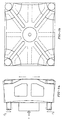
- FIGS. 1a and 1b disclose a prior art molding platen having a shape slightly different than the block shape platens discussed above in the cited patents.
- the mold platen has a profile including several openings therethrough, a front wall and a back wall.
- a plurality of slots and ribs extend toward the back wall which can and has a smaller surface area than the front wall of the platen.
- the platen also includes bores at each corner thereof for receiving tension bars that resist the force F between the platens during mold clamp-up.
- Each tie bar carries a resistance force F R as shown.
- the plurality of ribs and slots are provided for decreasing the weight of the platen.
- the front mold mounting face is under compression during mold clamp-up while the back wall is under tension as in a simple beam.
- the tie bars are drawn inwardly and deform to conform with platen face movement, as shown by the dotted line and arrows in Figure 1a , thereby causing the mold face to bend and have a concave configuration during molding, similar to the platens of the aforementioned patents. Accordingly, despite the design of the mold platen of FIGS. 1a and 1b, mold face bending is not compensated for and the possibility of the creation of flash is still existent. Since both sides of the platen bend, the supports at the corners of the tie bars also bend resulting in uneven loading of the tie bar supports. This causes bending of the tie bars and high stress concentrations leading to premature fatigue failure. Arrows C show how the tie bars are bent during clamp-up.
- WO-A-9211991 discloses a movable mold support platen for an injection molding machine in which the platen is in a form of a box-like structure that includes spaced front and rear plates.
- the platen includes a plurality of longitudinally extending beam members that interconnect the front and rear plates and are positioned in parallel relationship and in a generally rectangular array.
- the platen structure can accept non-axial actuating forces without excessive wear between tie rod bores and tie rods.
- the primary object of this invention is to provide a mold platen for use with molding or clamping or pressing applications which results in substantially flat and parallel mold mounting faces during clamp-up.
- Another object of this invention is to provide a mold platen for use in injection molding applications as above which is lightweight.
- Still another object of this invention is to provide a mold platen designed to direct clamping force during clamp-up from the tie bars at the edges of the platen towards the center mold mounting area of the platen eliminating any curvature of the platen.
- Still another object of this invention is to provide a mold platen having a mold mounting face which stays almost completely flat during clamp-up and substantially prevents the formation of flash.
- a further object of this invention is to provide a mold platen having two sides and an intermediate support structure which prevents the mold platen from non-uniformly deflecting at the molding side during clamp-up.
- Yet another object of this invention is to provide a mold platen having two walls and a central arch-shaped intermediate support structure between the two walls which substantially prevents non-uniform platen deflection at the molding side.
- Yet another object of this invention is to provide a mold platen having two sides and an intermediate conically-shaped support structure for substantially preventing non-uniform platen deflection at the molding side.
- Another object of the present invention is to provide a mold platen for eliminating uneven loading of tie bars and nuts during clamp-up.
- platen 10 includes a mold mounting wall 12 adapted to hold a mold half 17, an end wall 14 and intermediate support structure 16 positioned between molding wall 12 and end wall 14.
- FIGS. 4 and 5 represents additional embodiments of the platen of the present invention and from a general standpoint, the embodiments of FIGS. 2, 4 and 5 are similar.
- FIG. 4 represents the particularly preferred embodiment, i.e. one with angled instead of arched walls or one having a conically shaped intermediate portion, as shown in FIG. 5.
- FIG. 5 represents the particularly preferred embodiment, i.e. one with angled instead of arched walls or one having a conically shaped intermediate portion, as shown in FIG. 5.
- Mold mounting wall 12 is adapted to hold a mold half 17 for use in mating another mold half (not shown) for creating a mold and for sufficiently clamping the other mold half via clamping force F represented by the arrows. Reaction forces F R in tie bars 25 are further represented by the arrows. Mold mounting wall 12 is substantially rectangular in shape, although other shapes can be used, extends substantially transverse to force F, and preferably, on one of two platens on a machine, includes an aperture 18 through the center thereof for insertion of an injection unit 20. As shown in the cross-sectional view of FIG. 2, the tip 22 of injection unit 20 preferably extends through aperture 18 to connect with mold half 17 thereby contributing to efficient space utilization. Mold mounting wall 12 also includes a bore 24 being substantially larger in diameter than tie bar 25 at each corner thereof for receiving tie bars 25. Mold mounting wall 12 is adapted to receive four tie bars 25 which extend therethrough and toward end wall 14.
- Intermediate support structure 16 provides a mechanism by which mold mounting wall 12 of platen 10 is prevented from non-uniformly bending during the application of clamping force F and as a result of such non-uniform bending, preventing the creation of flash and wear on the components of the molding machine.
- Intermediate support structure 16 includes one or more internal ribs 26 and/or 28 extending from inner side 27 of mold mounting wall 12 to inner side 29 of end wall 14, causing the intermediate support structure to have a narrow end and a wide end.
- the intermediate support structure is preferably one continuous wall in a semi-spherical or conical shape which is attached to the end wall and mold mounting wall similar to as described below with respect to the upper and lower ribs.
- Ribs 26 and 28 are attached to and extend substantially outwardly from a central area 30 of inner side 27 of mold mounting wall 12, forming a narrow end, to the outer edges, 32 and 34, respectively, of the inner side 29 of end wall 14, forming a wide end and cavity 31 between ribs 26 and 28. Accordingly, central area 30 is located opposite the intended mold mounting area of mold mounting wall 12. Ribs 26 and 28 therefore support the platen face directly where the mold is located. Accordingly, in one embodiment, a singular upper rib 26 extends from central area 30 of mold mounting wall 12 to, and is attached with, an upper edge 32 of inner side 29 of end wall 14. Preferably, upper rib 26 is attached to and extends across the entire width of inner side 27 of molding wall 12 as shown in the perspective view of FIG.
- lower rib 28 is also attached to, and extends from central area 30, preferably along the entire width of inner side 27 of mold mounting wall 12 and is attached with the lower edge 34 of inner side 29 of wall 14. While ribs 26 and 28 have been described as substantially contiguous and extending across the entire width, the present invention also contemplates ribs 26 and 28 being comprised of a plurality of separate ribs having smaller widths and spaced from each other and not necessarily covering the entire width of the mold mounting and end walls.
- the resulting structure formed by upper rib 26 and lower rib 28 is substantially arch or C-shaped, wherein each rib is bowed outwardly relative cavity 31 of platen 10.
- upper rib 126 and lower rib 128 are substantially straight, extending from central area 130 to upper edge 132 and lower edge 134, respectively, of end wall 114.
- the resulting shape is substantially V-shaped.
- the cross-section taken horizontally could be substantially the same to define another embodiment, i.e. such as the conical version shown in FIG. 5.
- FIG. 4 would not include holes 124 and the portion of tie bars 125 seen in cavity 131 would not be seen since wall 226 would block the view.
- intermediate support structure 216 comprises a wall 226 which is conical or spherical in shape with the narrow portion of the conical or spherical shape attached to the inner surface 227 of mold mounting wall 212 and the wide portion of the conical or spherical shape attached to the inner surface 229 of end platen 214.
- the conical or spherical wall may be divided into sections for ease of manufacture, or may be a singular casted part. Due to the conical or spherical shape, the wall 226 of intermediate 216 typically would not extend across the entire width of the end and mold mounting walls as described above for the FIGS. 2 and 4 embodiments.
- the upper and lower ribs of the intermediate support structure or wall of the conically or spherically shaped support structure are attached with molding wall 12, 112, or 212, respectively, at an acute angle ⁇ thereto (not shown in FIG. 5, but similar to FIG. 4) and to end wall 14, 114, or 214, respectively, at an acute angle ⁇ thereto (not shown in FIG. 5, but similar to FIG. 4).
- End wall 14 is also preferably rectangular in shape, although other shapes may be used, and extends substantially parallel wall 12, transverse force F, and may include an aperture 36 therethrough in which injection unit 20 can be adapted to extend for injecting melt into mold half 17. Similar to molding wall 12, end wall 14 includes bores 38 in alignment with bores 24, one at each corner thereof, in order to receive tie bars therethrough. Each of bores 38 may include, if necessary, a countersink 40 for receiving tie bar nuts 42. Upper rib 26 and lower rib 28 may also include openings 48 and 50, respectively, therein and in alignment with bores 24 and 38 of walls 12 and 14 for receiving tie bars 25 as required.
- End wall 14 further can include purge openings 44 therein adjacent ribs 26 and 28, through which escaping melt, purgings and/or drool may exit from the platen by running down the inner surface 46 of lower rib 28 and through the purge opening 44.
- the platens as shown are formed from a casted material, it is also feasible the elements thereof, i.e. the walls and intermediate support structure, may be formed separately and fastened together in any manner which will provide the necessary strength to withstand forces developed during clamp-up.
- platen 10 can be used, for example, with both movable and stationary platens used in molding machines and mechanical presses or other clamping mechanisms wherein deflection of a platen is possible due to clamp-up forces generated, and in both singular and tandem designs of these molding machines and presses and other clamping mechanisms.
- intermediate support structure 16 and the arrangement of mold mounting wall 12 relative intermediate support structure 16 is such that the clamping forces F at the edges of the platens are directed towards the center of the platen where the mold half is located, i.e functioning on a bridge principle to provide support directly under the mold. Accordingly, the mold mounting face of the platen deforms in a substantially parallel manner thereby substantially preventing bending and the creation of flash.
- the force F which develops on the mold mounting surface of platen 10 during clamp-up is indicated by the large arrow in FIG. 2.
- the force F acting on the platen during mold clamp-up is dissipated outwardly as force F I , as indicated by the small arrows, along internal ribs 26 and 28 causing the intermediate support structure 16 to be in compression as indicated by the arrows C and causing the molding face of wall 12 to be in a neutral state in terms of bending forces acting unopposed thereon.
- end wall 14 is caused to be in tension as indicated by arrows T while the tie bars each with reaction force F R are pushed slightly outwardly due to stretching of end wall 14.
- the primary advantage of this invention is that a platen is provided for use with molding or clamping or pressing applications which results in substantially flat and parallel mold mounting faces during clamp-up.
- a platen is provided for use in injection molding applications which is lightweight.
- a platen is provided which is designed to direct clamping force during clamp-up from the tie bars at the edges of the platen towards the center mold mounting area of the platen, eliminating any curvature of the platen.
- a platen is provided having a mold mounting face which stays almost completely flat during clamp-up and substantially prevents the formation of flash.
- a platen is provided having two walls and an intermediate support structure which prevents the mold mounting side of the platen from non-uniformly deflecting during clamp-up.
- a platen is provided having two walls and a central arch-shaped intermediate support structure between the two walls which substantially prevents non-uniform platen deflection of the mold mounting side thereof.
- a platen is provided having two walls and an intermediate conically or spherically shaped support structure therebetween for substantially preventing non-uniform platen deflection at the molding side.
- Another object of the present invention is to provide a mold platen for eliminating uneven loading of tie bars and nuts during clamp up. Since bending of the platen is minimized, the loading of the tie bars is substantially uniform and any resulting tie bar bending is substantially eliminated.
Landscapes
- Engineering & Computer Science (AREA)
- Manufacturing & Machinery (AREA)
- Mechanical Engineering (AREA)
- Moulds For Moulding Plastics Or The Like (AREA)
- Handling Of Sheets (AREA)
- Polishing Bodies And Polishing Tools (AREA)
- Diaphragms For Electromechanical Transducers (AREA)
- Presses And Accessory Devices Thereof (AREA)
- Electroplating Methods And Accessories (AREA)
- Devices For Use In Laboratory Experiments (AREA)
Abstract
Description
- The present invention is directed to platens used with molding machines and presses, and more particular to a platen having a design which allows for minimum platen deflection at minimum platen weight.
- Injection molding platens are typically block shaped as shown in U.S. Patent No. 5,188,850 to Hirata et al.; U.S. Patent No. 5,066,217 to Fukuzawa et al.; U.S. Patent No. 5,110,283 to Blüml et al.; U.S. Patent No. 5,162,782 to Yoshioka; and U.S. Patent No. 5,192,557 to Hirata et al. In each of these patents, the mold platen is substantially block shaped having a substantially rectangular side which supports a mold half. During clamp-up of mold halves, a force is generated against the mold mounting face of the platen. As is typical with such block shaped platens, the mold mounting face is caused to concavely deform, forcing the top and bottom edges of the side towards the oncoming force and causing the platen to bend and provide tension across the backside of the mold platen. As a result, under the clamp-up force the center of the platens separate causing a gap between the mold halves, and in some cases, the formation of flash is a by-product.
- U.S. Patent No. 4,615,857 to Baird discloses an encapsulation means and method for reducing flash during mold operations. In accordance with this device, it is alleged that injection and transfer molding of plastic is performed in a manner that virtually eliminates flash. Deflection of the mold press therein is measured with the mold press in the clamping configuration. The support structure of the mold is arranged to apply an equal force to the mold face by configuring supporting pillars and bars such that they act as individual springs against the mold face and in response to the force generated while the mold is in the clamping configuration. The spring constants and the lengths of the supporting pillars and bars are calculated to account for the actual deflection found in the mold press and thereby producing a uniform pressure on the molds during clamping of the press.
- Accordingly, the flexure of the mold platens during mold sealing is measured and the compressibility of the mold mounting blocks of the device are adjusted as a function of lateral position on one or both platens in order to compensate for platen flexure, so that a constant force is applied to the parting surface of the mold, independent of lateral position on the parting surface. The stiffness and length of the mounting blocks define the force provided by the mounting blocks and are determined in accordance with predetermined formulas depending upon the position of the block on the platen and the predetermined platen deflection. While Baird compensates for deflection, the method and apparatus by which this is achieved is quite complex requiring individual designs for particular forces to be generated with particular molds. Accordingly, a uniformly applicable design is not achieved.
- FIGS. 1a and 1b disclose a prior art molding platen having a shape slightly different than the block shape platens discussed above in the cited patents. As shown in Figure 1a , the mold platen has a profile including several openings therethrough, a front wall and a back wall. As shown in FIG. 1b, a plurality of slots and ribs extend toward the back wall which can and has a smaller surface area than the front wall of the platen. The platen also includes bores at each corner thereof for receiving tension bars that resist the force F between the platens during mold clamp-up. Each tie bar carries a resistance force FR as shown. The plurality of ribs and slots are provided for decreasing the weight of the platen. That is, the front mold mounting face is under compression during mold clamp-up while the back wall is under tension as in a simple beam. The tie bars are drawn inwardly and deform to conform with platen face movement, as shown by the dotted line and arrows in Figure 1a , thereby causing the mold face to bend and have a concave configuration during molding, similar to the platens of the aforementioned patents. Accordingly, despite the design of the mold platen of FIGS. 1a and 1b, mold face bending is not compensated for and the possibility of the creation of flash is still existent. Since both sides of the platen bend, the supports at the corners of the tie bars also bend resulting in uneven loading of the tie bar supports. This causes bending of the tie bars and high stress concentrations leading to premature fatigue failure. Arrows C show how the tie bars are bent during clamp-up.
- There exists, therefore, a need for a simply designed and lightweight platen which includes means for compensating for platen deflection during mold or press clamp-up and which substantially eliminates the creation of flash.
- WO-A-9211991 discloses a movable mold support platen for an injection molding machine in which the platen is in a form of a box-like structure that includes spaced front and rear plates. The platen includes a plurality of longitudinally extending beam members that interconnect the front and rear plates and are positioned in parallel relationship and in a generally rectangular array. The platen structure can accept non-axial actuating forces without excessive wear between tie rod bores and tie rods.
- The primary object of this invention is to provide a mold platen for use with molding or clamping or pressing applications which results in substantially flat and parallel mold mounting faces during clamp-up.
- Another object of this invention is to provide a mold platen for use in injection molding applications as above which is lightweight.
- Still another object of this invention is to provide a mold platen designed to direct clamping force during clamp-up from the tie bars at the edges of the platen towards the center mold mounting area of the platen eliminating any curvature of the platen.
- Still another object of this invention is to provide a mold platen having a mold mounting face which stays almost completely flat during clamp-up and substantially prevents the formation of flash.
- And still a further object of this invention is to provide a mold platen having two sides and an intermediate support structure which prevents the mold platen from non-uniformly deflecting at the molding side during clamp-up.
- And yet another object of this invention is to provide a mold platen having two walls and a central arch-shaped intermediate support structure between the two walls which substantially prevents non-uniform platen deflection at the molding side.
- And yet another object of this invention is to provide a mold platen having two sides and an intermediate conically-shaped support structure for substantially preventing non-uniform platen deflection at the molding side.
- Another object of the present invention is to provide a mold platen for eliminating uneven loading of tie bars and nuts during clamp-up.
- The foregoing objects are achieved by the features of
independent claims 1, 11, 15 and 27. Preferred embodiments are subject of dependent claims. The purpose of the second wall is to resist the separation forces created by the intermediate structure. - The details of the present invention are set out in the following description and drawings wherein like reference characters depict like elements.
-
- FIG. 1a is a side elevational view of a mold platen of the prior art and the forces and deflections which take place during a clamp-up using this mold platen;
- FIG. 1b is a front elevational view of the mold platen of the prior art shown in FIG. 1a;
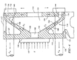
- FIG. 2 is an elevational sectional view of the platens of FIGS. 3 and 5 in accordance with the principles of the present invention;
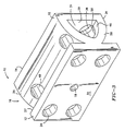
- FIG. 3 is a perspective view of the platen of FIG. 2;
- FIG. 4 is an elevational sectional view of another embodiment of a platen in accordance with the principles of the present invention; and
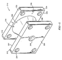
- FIG. 5 is a perspective view of another embodiment of a platen in accordance with the principles of the present invention, also represented by the sectional view of FIG. 2.
-
- Referring now to the drawings in detail, there is shown in FIG. 2, an elevational and cross sectional view of a first embodiment of the platen of the present invention for use in a molding application, and in FIG. 3 a perspective view of the platen shown in FIG. 2, designated generally as 10. Generally,
platen 10 includes amold mounting wall 12 adapted to hold amold half 17, anend wall 14 andintermediate support structure 16 positioned betweenmolding wall 12 andend wall 14. - FIGS. 4 and 5 represents additional embodiments of the platen of the present invention and from a general standpoint, the embodiments of FIGS. 2, 4 and 5 are similar. FIG. 4 represents the particularly preferred embodiment, i.e. one with angled instead of arched walls or one having a conically shaped intermediate portion, as shown in FIG. 5. The foregoing and following description, unless otherwise indicated, applies equally to all embodiments and with regard to the figures, like numerals designate like elements.
- Mold
mounting wall 12 is adapted to hold amold half 17 for use in mating another mold half (not shown) for creating a mold and for sufficiently clamping the other mold half via clamping force F represented by the arrows. Reaction forces FR in tie bars 25 are further represented by the arrows. Mold mountingwall 12 is substantially rectangular in shape, although other shapes can be used, extends substantially transverse to force F, and preferably, on one of two platens on a machine, includes anaperture 18 through the center thereof for insertion of aninjection unit 20. As shown in the cross-sectional view of FIG. 2, thetip 22 ofinjection unit 20 preferably extends throughaperture 18 to connect withmold half 17 thereby contributing to efficient space utilization. Mold mountingwall 12 also includes abore 24 being substantially larger in diameter thantie bar 25 at each corner thereof for receiving tie bars 25. Mold mountingwall 12 is adapted to receive fourtie bars 25 which extend therethrough and towardend wall 14. -
Intermediate support structure 16 provides a mechanism by whichmold mounting wall 12 ofplaten 10 is prevented from non-uniformly bending during the application of clamping force F and as a result of such non-uniform bending, preventing the creation of flash and wear on the components of the molding machine. -
Intermediate support structure 16 includes one or moreinternal ribs 26 and/or 28 extending frominner side 27 ofmold mounting wall 12 toinner side 29 ofend wall 14, causing the intermediate support structure to have a narrow end and a wide end. For the FIG. 5 embodiment, the intermediate support structure is preferably one continuous wall in a semi-spherical or conical shape which is attached to the end wall and mold mounting wall similar to as described below with respect to the upper and lower ribs. -
Ribs central area 30 ofinner side 27 ofmold mounting wall 12, forming a narrow end, to the outer edges, 32 and 34, respectively, of theinner side 29 ofend wall 14, forming a wide end andcavity 31 betweenribs central area 30 is located opposite the intended mold mounting area ofmold mounting wall 12.Ribs upper rib 26 extends fromcentral area 30 ofmold mounting wall 12 to, and is attached with, anupper edge 32 ofinner side 29 ofend wall 14. Preferably,upper rib 26 is attached to and extends across the entire width ofinner side 27 ofmolding wall 12 as shown in the perspective view of FIG. 3, although this design may be deviated from as discussed below. Similarly,lower rib 28 is also attached to, and extends fromcentral area 30, preferably along the entire width ofinner side 27 ofmold mounting wall 12 and is attached with thelower edge 34 ofinner side 29 ofwall 14. Whileribs ribs - With particular reference to FIG. 2 and the embodiment shown therein, the resulting structure formed by
upper rib 26 andlower rib 28 is substantially arch or C-shaped, wherein each rib is bowed outwardlyrelative cavity 31 ofplaten 10. - Referring with particularity to FIG. 4 and the embodiment shown therein, upper rib 126 and
lower rib 128 are substantially straight, extending fromcentral area 130 toupper edge 132 andlower edge 134, respectively, ofend wall 114. In this embodiment, the resulting shape is substantially V-shaped. The cross-section taken horizontally could be substantially the same to define another embodiment, i.e. such as the conical version shown in FIG. 5. As representative of the cross-section of the FIG. 5 embodiment, FIG. 4 would not includeholes 124 and the portion of tie bars 125 seen incavity 131 would not be seen sincewall 226 would block the view. - With particular reference to FIG. 5, and the embodiment shown therein,
intermediate support structure 216 comprises awall 226 which is conical or spherical in shape with the narrow portion of the conical or spherical shape attached to theinner surface 227 ofmold mounting wall 212 and the wide portion of the conical or spherical shape attached to theinner surface 229 ofend platen 214. The conical or spherical wall may be divided into sections for ease of manufacture, or may be a singular casted part. Due to the conical or spherical shape, thewall 226 of intermediate 216 typically would not extend across the entire width of the end and mold mounting walls as described above for the FIGS. 2 and 4 embodiments. - In the FIGS. 2, 4 and 5 embodiments, the upper and lower ribs of the intermediate support structure or wall of the conically or spherically shaped support structure are attached with
molding wall wall -
End wall 14 is also preferably rectangular in shape, although other shapes may be used, and extends substantiallyparallel wall 12, transverse force F, and may include anaperture 36 therethrough in whichinjection unit 20 can be adapted to extend for injecting melt intomold half 17. Similar tomolding wall 12,end wall 14 includesbores 38 in alignment withbores 24, one at each corner thereof, in order to receive tie bars therethrough. Each ofbores 38 may include, if necessary, acountersink 40 for receiving tie bar nuts 42.Upper rib 26 andlower rib 28 may also includeopenings bores walls End wall 14 further can includepurge openings 44 thereinadjacent ribs inner surface 46 oflower rib 28 and through thepurge opening 44. - While the platens as shown are formed from a casted material, it is also feasible the elements thereof, i.e. the walls and intermediate support structure, may be formed separately and fastened together in any manner which will provide the necessary strength to withstand forces developed during clamp-up.
- In operation,
platen 10 can be used, for example, with both movable and stationary platens used in molding machines and mechanical presses or other clamping mechanisms wherein deflection of a platen is possible due to clamp-up forces generated, and in both singular and tandem designs of these molding machines and presses and other clamping mechanisms. - During clamp-up while using
platen 10,intermediate support structure 16 and the arrangement ofmold mounting wall 12 relativeintermediate support structure 16 is such that the clamping forces F at the edges of the platens are directed towards the center of the platen where the mold half is located, i.e functioning on a bridge principle to provide support directly under the mold. Accordingly, the mold mounting face of the platen deforms in a substantially parallel manner thereby substantially preventing bending and the creation of flash. - The force F which develops on the mold mounting surface of
platen 10 during clamp-up is indicated by the large arrow in FIG. 2. The force F acting on the platen during mold clamp-up is dissipated outwardly as force FI, as indicated by the small arrows, alonginternal ribs intermediate support structure 16 to be in compression as indicated by the arrows C and causing the molding face ofwall 12 to be in a neutral state in terms of bending forces acting unopposed thereon. In addition,end wall 14 is caused to be in tension as indicated by arrows T while the tie bars each with reaction force FR are pushed slightly outwardly due to stretching ofend wall 14. As a result of this action of forces on and within the platen, the mold mounting face ofmolding wall 12 is not non-uniformly deflected. The force distribution described above is applicable equally to each of the embodiments enclosed herewith, i.e. the arch or C-shaped intermediate support structure and the V-shaped intermediate support structure shown in FIGS. 2 and 4, respectively and also the conically or spherically shaped intermediate support structure shown in FIG. 5. - The primary advantage of this invention is that a platen is provided for use with molding or clamping or pressing applications which results in substantially flat and parallel mold mounting faces during clamp-up. Another object of this invention is that a platen is provided for use in injection molding applications which is lightweight. Still another object of this invention is that a platen is provided which is designed to direct clamping force during clamp-up from the tie bars at the edges of the platen towards the center mold mounting area of the platen, eliminating any curvature of the platen. Still another object of this invention is that a platen is provided having a mold mounting face which stays almost completely flat during clamp-up and substantially prevents the formation of flash. And still a further object of this invention is that a platen is provided having two walls and an intermediate support structure which prevents the mold mounting side of the platen from non-uniformly deflecting during clamp-up. And yet another object of this invention is that a platen is provided having two walls and a central arch-shaped intermediate support structure between the two walls which substantially prevents non-uniform platen deflection of the mold mounting side thereof. And yet another object of this invention is that a platen is provided having two walls and an intermediate conically or spherically shaped support structure therebetween for substantially preventing non-uniform platen deflection at the molding side. Another object of the present invention is to provide a mold platen for eliminating uneven loading of tie bars and nuts during clamp up. Since bending of the platen is minimized, the loading of the tie bars is substantially uniform and any resulting tie bar bending is substantially eliminated.
- It is to be understood that the invention is not limited to the illustrations described and shown herein, which are deemed to be merely illustrative of the best modes of carrying out the invention, and which are susceptible of modification of form, size, arrangement of parts and details of operation. The invention rather is intended to encompass all such modifications which are within its scope as defined by the claims.
Claims (30)
- A platen for use in a clamping operation wherein a force (F) is generated in a first direction, comprising:
a mold platen (10,110,210) having two walls spaced from each other, with a first of said walls (12,112,212) being on the mold side and a second of said walls (14,114,214) being spaced from and parallel to said first wall, wherein said first and second walls extend substantially transverse to said first direction of said force (F), wherein each of said first and second walls have edges and a center area and wherein an intermediate support structure (16,116,216) is positioned between and connected to both of said walls,
characterized in that
said intermediate support structure (16,116,216) is adapted for directing said force away from the edges of said first wall toward the center area of said first wall for substantially preventing deflection of said first wall and has a narrow end and a wide end and is arch shaped, conically shaped, V-shaped or C-shaped. - A platen according to claim 1, wherein said support structure (16,116,216) is one continuous wall.
- A platen according to claim 1 or 2, wherein said support structure (16,116,216) is hollow.
- A platen according to one of the claims 1 to 3, wherein said support structure (16,116,216) extends substantially outwardly from the center area of one wall toward the edge of the other wall.
- A platen according to one of the claims 1 to 4, wherein said walls have a width and wherein said support structure (16,116,216) extends across the entire width of at least one of said walls.
- A platen according to one of the claims 1 to 5, wherein said support structure (16,116,216) extends outwardly from the center area of one wall at an acute angle to said one wall, and to the other wall at an acute angle to said other wall.
- The platen according to one of the claims 1 to 6, further including means for receiving an injection unit (20) through said first and second walls (12,112,212; 14,114,214) and through said intermediate support structure (16,116,216).
- The platen according to claim 7, wherein said second wall (14,114,214) includes means for removing drool resulting from a molding operation using said injection unit (20).
- The platen according to claim 8, wherein said means for removing comprises an inner surface (46) of said support wall leading to a purge hole (44) through said second wall for allowing said drool to escape.
- The platen according to one of the claims 1 to 9, wherein said first wall (12,112,212) is adapted to support a first mold half (17,117,217) for engagement with a second mold half for forming a mold of an injection molding machine.
- A method for distributing forces within a platen having two parallel walls spaced apart by an intermediate support structure (16,116,216) positioned between and connected to both of said walls, which comprises:characterized in thatproviding a mold platen (10,110,210) having two walls spaced from each other, with a first of said walls (12,112,212) being on the mold side and a second of said walls (14,114,214) being spaced from and parallel to said first wall, wherein each of said two walls have edges and a center area;clamping together the two mold halves thereby generating a force (F) againstat least one of said walls in a first direction, wherein said walls extend substantially transverse to said first direction,
said force is directed away from the edges of said first wall toward the center area of said first wall via said intermediate support structure (16,116,216) thereby substantially preventing deflection of said first wall, wherein said force is directed via said intermediate support structure (16,116,216) having a narrow end and a wide end and having an arch shape, a conical shape, a V-shape or a C-shape. - A method according to claim 11, including the step of extending said intermediate support structure (16,116,216) substantially outwardly from a center area of one wall towards edges of the other wall.
- A method according to claim 11 or 12, wherein said walls have a width, including the step of extending said intermediate support structure (16,116,216) across the entire width of at least one of said walls.
- A method according to one of the claims 11 to 13, including the step of extending said intermediate support structure (16,116,216) outwardly from the center area of one wall at an acute angle to said one wall, and to the other wall at an acute angle to said other wall.
- An injection molding machine, comprising:
a platen (10,110,210) holding a first mold half adapted for use in mating with a second mold half for forming a cavity mold; means for guiding said platen (10, 110,210); and means for injection molding molten resin into said mold, wherein during clamping of said mold halves a force (F) is generated in said platen having a first direction substantially perpendicular to said platen, said platen including a first wall (12,112,212) having edges and a central area and at least first and second sides, wherein said first side is adapted to be positioned nearest said cavity mold, said cavity mold being adjacent said first wall (12, 112, 212) said platen (10,110,210) further including a second wall (14,114,214) spaced from a substantially parallel to said first wall (12,112,212), said first and second walls extending substantially transverse to said first direction of said force (F), and an intermediate support structure (16,116,216) positioned between and connected to both of said walls,
characterized in that
said intermediate support structure (16,116,216) is adapted for directing said force away from the edges of said first wall toward the center area of said first wall for substantially preventing deflection of said first wall and has a narrow and a wide end and is defined by one of (1) a substantially V-shaped support wall defining a cavity between said first (12,112,212) and second (14,114, 214) walls, (2) a substantially arch-shaped support wall, (3) a support wall having a substantially C-shaped cross-section, and (4) a conically shaped wall, thereby defining a cavity between said first and second walls, wherein said platen (10, 110,210) substantially eliminates platen curvature during clamping. - The injection molding machine according to claim 15, further including means for receiving means injection molding (20) through said first (12, 112, 212) and second (14,114,214) walls and through said intermediate support structure (16, 116,216).
- The injection molding machine according to claim 16, wherein said first (12, 112,212) and second (14,114,214) walls have openings (24,124,228; 38,138,238) therein leading to said cavity, (31,131,231), wherein said openings and said cavity are adapted to receive said means for injection molding (20).
- The injection molding machine according to claim 17, wherein said second wall (14,114,214) includes means for removing drool from said cavity (31,131,231) resulting from a molding operation using said means for injection molding (20).
- The injection molding machine according to claim 18, wherein said means for removing comprises an inner surface (46) of said support wall (28) leading to a purge hole (44) through said second wall (14) for allowing said drool to escape said cavity (31).
- The injection molding machine according to one of claims 15 to 19, further comprising said intermediate support structure (16) defined by an arch-shaped support wall having a narrow end and a wide end, wherein said first wall (12) is attached with said narrow end and said second wall (14) is attached with said wide end.
- The injection molding machine according to claim 20, wherein said second side of said first wall (12) is attached to said narrow end opposite said first side.
- The injection molding machine according to one of claims 15 to 21, wherein said means for directing is operative to prevent said first side of said first wall (12,112,212) from deflecting in a second direction transverse to said first direction.
- The injection molding machine according to one of claims 15 to 22, wherein said first (12,112,212) and second (14,114,214) wall and said intermediate support structure (16,116,216) form a hollow, symmetrical structure.
- The injection molding machine according to one of the claims 15 to 23, wherein said means for guiding comprise tiebars (25,125,225).
- The injection molding machine according to one of the claims 15 to 24, wherein the intermediate support structure (16,116,216) is defined by a support having an outer surface forming an acute angle with respect to said first direction of said force.
- The injection molding machine according to claim 24, wherein said tiebars (25, 125,225) pass through at least one of said walls with a clearance between said tiebars and said at least one of said walls.
- A method for reducing flash formation during injection molding, comprising the steps of:
forming a cavity mold between a stationary platen holding a first mold half and a movable platen holding a second mold half, wherein at least one of said platens includes a first wall (12,112,212)nearest said cavity mold having edges and a central area (30,130,230) and a second wall (14,114,214) spaced from and substantially parallel to said first wall by an intermediate support structure (16,116,216) positioned between and connected to both of said walls; clamping together the two mold halves thereby generating a force (F) having a first direction against said at least one platen (10,110,210) substantially perendicular to said at least one platen;
characterized in that
said force (F) is directed away from the edges of said first wall of said at least one platen (10,110,210) toward the center area of said first wall via said intermediate support structure (16,116,216), thereby substantially preventing deflection of said first wall and the formation of flash, wherein said force is directed via said intermediate support structure (16,116,216) having a narrow end and a wide end and having an arch shape, a conical shape, a V-shape or a C-shape, and injecting molding resin into said cavity mold and forming a molded part. - The method according to claim 27, further including the step of receiving said molten resin through said first (12,112,212) and second (14,114,214) walls and through said intermediate support structure (16,116,216).
- The method according to claim 27 or 28, further including the step of removing drool from said intermediate support structure (16,116,216) resulting from said step of injection molding.
- The method according to one of the claims 27 to 29, wherein said step of directing includes the step of preventing a first side of said first wall (12,112,212) from deflecting in a second direction transverse to said first direction by the said intermediate support structure (16,116,216).
Applications Claiming Priority (2)
| Application Number | Priority Date | Filing Date | Title |
|---|---|---|---|
| US482874 | 1995-06-07 | ||
| US08/482,874 US5593711A (en) | 1995-06-07 | 1995-06-07 | Uniformly compressible platen |
Publications (3)
| Publication Number | Publication Date |
|---|---|
| EP0747196A1 EP0747196A1 (en) | 1996-12-11 |
| EP0747196B1 true EP0747196B1 (en) | 2001-08-16 |
| EP0747196B2 EP0747196B2 (en) | 2005-04-27 |
Family
ID=23917793
Family Applications (1)
| Application Number | Title | Priority Date | Filing Date |
|---|---|---|---|
| EP96810360A Expired - Lifetime EP0747196B2 (en) | 1995-06-07 | 1996-06-04 | Uniformly compressible platen |
Country Status (8)
| Country | Link |
|---|---|
| US (2) | US5593711A (en) |
| EP (1) | EP0747196B2 (en) |
| JP (1) | JP2858647B2 (en) |
| AT (1) | ATE204226T1 (en) |
| CA (1) | CA2177949C (en) |
| DE (1) | DE69614451T3 (en) |
| ES (1) | ES2162013T5 (en) |
| MX (1) | MX9602232A (en) |
Cited By (2)
| Publication number | Priority date | Publication date | Assignee | Title |
|---|---|---|---|---|
| DE10215947B4 (en) * | 2002-04-11 | 2005-03-10 | Krauss Maffei Kunststofftech | Plate for an injection molding machine |
| DE102014006241A1 (en) | 2013-04-29 | 2014-10-30 | Engel Austria Gmbh | Vertical clamping unit for an injection molding machine |
Families Citing this family (58)
| Publication number | Priority date | Publication date | Assignee | Title |
|---|---|---|---|---|
| US5593711A (en) * | 1995-06-07 | 1997-01-14 | Husky Injection Molding Systems Ltd. | Uniformly compressible platen |
| US5910328A (en) * | 1996-02-22 | 1999-06-08 | Toshiba Kikai Kabushiki Kaisha | Clamping apparatus for precise injection molding |
| DE19608135C2 (en) * | 1996-03-02 | 1998-01-15 | Hemscheidt Maschtech Schwerin | Mold closing device for a mold of an injection molding machine |
| US6027329A (en) * | 1997-03-15 | 2000-02-22 | Hpm/Stadco, Inc. | Platen having internal spring-like characteristics for preventing deformation of mold mounting face during clamping operations |
| AT407852B (en) * | 1997-12-03 | 2001-07-25 | Engel Gmbh Maschbau | DEVICE FOR INJECTION MOLDING PLASTIC |
| BR9800139C1 (en) | 1998-03-23 | 2000-03-14 | Ind Romi S A Ind Romi S A | Development in mold locking mechanism |
| TW386521U (en) * | 1998-06-18 | 2000-04-01 | Tsai Wen Feng | Improvement of labeling device for CD, optical disk |
| US6439876B1 (en) | 2000-10-30 | 2002-08-27 | Husky Injection Molding Systems, Ltd. | Injection molding machine having a platen for uniform distribution of clamping forces |
| DE10123104A1 (en) * | 2001-05-12 | 2002-11-14 | Mannesmann Plastics Machinery | Mold clamping plate for injection molding machine consists of central plate with sleeves at its corners which surround bores for spindles of spindle drive, sleeves being only partially connected to plate |
| DE10132970A1 (en) * | 2001-07-06 | 2003-01-23 | Mannesmann Plastics Machinery | Mold platen for an injection molding machine |
| TW523453B (en) * | 2001-07-13 | 2003-03-11 | Sumitomo Heavy Industries | Injection-molding machine having movable mold support device |
| JP3715246B2 (en) * | 2001-07-13 | 2005-11-09 | 住友重機械工業株式会社 | Movable mold support device for injection molding machine |
| DE20114341U1 (en) * | 2001-08-30 | 2001-12-06 | Battenfeld Gmbh, 58540 Meinerzhagen | Plate of an injection molding machine |
| DE10144992A1 (en) * | 2001-09-12 | 2003-03-27 | Mpm Beteiligungs Gmbh | Mold mounting plate for injection molding machine comprises dome-shaped element with a base for supporting the base plate |
| DE10214458A1 (en) * | 2002-03-30 | 2003-10-16 | Lehmann Gmbh & Co Kg | Tool clamping load distribution plate for an injection molding machine comprises an intermediate plate with a central foot and peripheral supports between machine platens |
| USD472566S1 (en) | 2002-05-29 | 2003-04-01 | Sumitomo Heavy Industries, Ltd. | Movable platen |
| US6855281B2 (en) * | 2002-10-28 | 2005-02-15 | The North Face Apparel Corp | Method of forming an article of footwear |
| US6905643B2 (en) * | 2002-12-04 | 2005-06-14 | Dow Global Technologies Inc. | Process for molding on a substrate |
| US7080978B2 (en) * | 2003-04-17 | 2006-07-25 | Husky Injection Molding Systems Ltd. | Platen |
| DE10349828A1 (en) * | 2003-10-25 | 2005-06-16 | W + S Solutions Gmbh & Co. Kg | Injection molding machine has platen shaped to deflect under pressure with optional hydraulic assistance so as to reduce mold leakage |
| ITRM20040107A1 (en) * | 2004-03-02 | 2004-06-02 | Sipa Societa Industrializzazio | DEVICE AND CONDITIONING METHOD OF PLASTIC OBJECTS. |
| US20070187871A1 (en) * | 2004-03-09 | 2007-08-16 | Sumitomo Heavy Industries, Ltd | Mold-supporting apparatus, molding machine, and molding method |
| ITRM20040163A1 (en) * | 2004-03-30 | 2004-06-30 | Sipa Societa Industrializzazio | MOLDING EQUIPMENT FOR BLOWING PLASTIC OBJECTS. |
| ITRM20040259A1 (en) * | 2004-05-25 | 2004-08-25 | Sipa Societa Industrializzazio | MOLD HOLDER CROSSBAR FOR MOLDING PRESS AND PRESS INCLUDING SUCH CROSSBAR. |
| JP2006198801A (en) * | 2005-01-18 | 2006-08-03 | Toyo Mach & Metal Co Ltd | Molding machine |
| JP4364924B2 (en) | 2005-04-25 | 2009-11-18 | 三菱重工プラスチックテクノロジー株式会社 | Clamping device, injection molding machine and injection molding method |
| US20070036879A1 (en) * | 2005-08-09 | 2007-02-15 | Andreas Ujma | Machine platen and an injection molding machine |
| US20070035067A1 (en) * | 2005-08-09 | 2007-02-15 | Andreas Ujma | Molding machine plasticizing unit sub-assembly and a method of reducing shearing effects in the manufacture of plastic parts |
| AT501743B1 (en) * | 2005-09-26 | 2006-11-15 | Engel Austria Gmbh | FORMUFSPANNPLATTE FOR AN INJECTION MOLDING MACHINE |
| JP4928133B2 (en) * | 2006-02-13 | 2012-05-09 | 東洋機械金属株式会社 | Molding machine |
| JP4047892B2 (en) * | 2006-03-23 | 2008-02-13 | ファナック株式会社 | Molding device for injection molding machine |
| US7318721B2 (en) * | 2006-03-30 | 2008-01-15 | Husky Injection Molding Systems Ltd. | Molding-system platen |
| JP2008162103A (en) * | 2006-12-27 | 2008-07-17 | Toshiba Mach Co Ltd | Mold clamping device and injection molding machine equipped therewith |
| US7857612B2 (en) * | 2007-01-24 | 2010-12-28 | Husky Injection Molding Systems Ltd. | Molding-system platen having anti-tilt structure |
| US20080175944A1 (en) * | 2007-01-24 | 2008-07-24 | Husky Injection Molding Systems Ltd. | Molding-System Platen having Anti-Tilt Structure |
| US7753668B2 (en) * | 2007-01-24 | 2010-07-13 | Husky Injection Molding Systems Ltd. | Platen assembly, molding system and method for platen orientation and alignment |
| CA2672963C (en) * | 2007-01-24 | 2011-03-08 | Husky Injection Molding Systems Ltd. | Molding-system platen having tie-bar accommodation corners that resist coplanar disorientation |
| US20080173190A1 (en) * | 2007-01-24 | 2008-07-24 | Husky Injection Molding Systems Ltd. | Molding-System Platen having Anti-Tilt Structure |
| US7798805B2 (en) * | 2007-01-24 | 2010-09-21 | Husky Injection Molding Systems Ltd. | Molding-system platen having tie-bar accommodation corners that resist coplanar disorientation |
| US20080175943A1 (en) * | 2007-01-24 | 2008-07-24 | Husky Injection Molding Systems Ltd. | Molding-System Platen having Anti-Tilt Structure |
| JP4276274B2 (en) * | 2007-07-04 | 2009-06-10 | ファナック株式会社 | Fixed platen of injection molding machine |
| DE202008010066U1 (en) | 2007-08-16 | 2008-10-16 | Netstal-Maschinen Ag | Device for an injection molding machine with a tool clamping plate |
| JP4625489B2 (en) * | 2007-09-18 | 2011-02-02 | 三菱重工プラスチックテクノロジー株式会社 | Mold platen, mold clamping device, injection molding machine |
| JP2010179623A (en) * | 2009-02-09 | 2010-08-19 | Ube Machinery Corporation Ltd | Stationery platen for injection molding machine |
| US20110200701A1 (en) * | 2009-12-21 | 2011-08-18 | Carsten Link | Platen for an injection molding machine |
| US8864485B2 (en) | 2010-12-03 | 2014-10-21 | Graham Engineering Corporation | Adjustable platen assembly for use in a clamp station |
| US9101976B2 (en) | 2010-12-29 | 2015-08-11 | Imac Inc. | Die casting machine and method |
| DE202011108818U1 (en) | 2011-12-08 | 2013-03-13 | Netstal-Maschinen Ag | Intermediate plate for an injection molding machine |
| US8646512B2 (en) | 2012-05-08 | 2014-02-11 | Honda Motor Co., Ltd. | Die brace and method of use thereof |
| JP5567066B2 (en) * | 2012-05-30 | 2014-08-06 | 株式会社名機製作所 | Injection molding machine |
| JP5976567B2 (en) * | 2013-02-14 | 2016-08-23 | 住友重機械工業株式会社 | Injection molding machine |
| US8840391B1 (en) * | 2013-03-29 | 2014-09-23 | Dan Sherrill | Drool shield for injection molding |
| JP5800881B2 (en) * | 2013-11-06 | 2015-10-28 | ファナック株式会社 | Mold mounting machine for injection molding machine |
| JP5883045B2 (en) | 2014-02-10 | 2016-03-09 | ファナック株式会社 | Fixed platen of injection molding machine |
| JP6329517B2 (en) * | 2014-08-04 | 2018-05-23 | 日精樹脂工業株式会社 | Clamping mechanism |
| JP6383705B2 (en) * | 2014-08-04 | 2018-08-29 | 日精樹脂工業株式会社 | Clamping mechanism |
| US11059210B2 (en) | 2017-06-28 | 2021-07-13 | Diseño Y Desarrollo De Matriceria, S.L. | Plastic injection molding machine and molding method |
| JP2023176518A (en) * | 2022-05-31 | 2023-12-13 | アピックヤマダ株式会社 | Resin sealing device |
Family Cites Families (24)
| Publication number | Priority date | Publication date | Assignee | Title |
|---|---|---|---|---|
| US1977549A (en) * | 1934-08-04 | 1934-10-16 | Rudolph W Glasner | Metal working press |
| US2807206A (en) * | 1952-09-01 | 1957-09-24 | Renault | Presses actuated by a fluid under pressure |
| US2719443A (en) * | 1953-03-16 | 1955-10-04 | Rohr Aircraft Corp | Drop hammer |
| US3669593A (en) * | 1970-02-10 | 1972-06-13 | Wilhelm Cyriax | Mold-closing means for molding machines |
| SE359257B (en) * | 1972-01-03 | 1973-08-27 | Asea Ab | |
| DE2443510A1 (en) * | 1974-09-11 | 1976-03-25 | Karl Hehl | MOLD CLAMPING UNIT OF AN INJECTION MOLDING MACHINE |
| US4243369A (en) * | 1978-12-05 | 1981-01-06 | Micro & Precision Mouldings (Cheltenham Limited) | Mould closing, clamping and opening means |
| SE429944B (en) * | 1982-03-22 | 1983-10-10 | Fjellman Press Ab | HOGTRYCKSPRESS |
| JPS6044200A (en) * | 1983-08-22 | 1985-03-09 | Kootaki Kk | Pressure equalizing press device |
| US4615857A (en) * | 1984-11-30 | 1986-10-07 | Motorola, Inc. | Encapsulation means and method for reducing flash |
| US4613475A (en) * | 1985-02-19 | 1986-09-23 | Siebolt Hettinga | Clamping structure and method for clamping the mold unit of a mold injection apparatus |
| JPH0641160B2 (en) * | 1989-02-15 | 1994-06-01 | 東芝機械株式会社 | Mold clamping device |
| US4976400A (en) * | 1989-06-16 | 1990-12-11 | General Motors Corporation | Plastic tooling with compression adjustment |
| JPH0383120A (en) * | 1989-08-28 | 1991-04-09 | Mitsubishi Electric Corp | Display device with coordinate input function |
| US5059105A (en) * | 1989-10-23 | 1991-10-22 | Motorola, Inc. | Resilient mold assembly |
| US5100283A (en) * | 1990-03-15 | 1992-03-31 | U-Haul International, Inc. | Hitch hoist |
| US5192557A (en) * | 1990-07-27 | 1993-03-09 | Nissei Jushi Kogyo K.K. | Clamping apparatus for molding machine |
| US5188850A (en) * | 1990-07-27 | 1993-02-23 | Nissie Jushi Kogyo K.K. | Clamping apparatus for molding machine |
| US5066217A (en) * | 1990-08-08 | 1991-11-19 | Ube Industries, Ltd. | Clamping apparatus for an injection molding machine |
| US5163363A (en) * | 1991-01-09 | 1992-11-17 | International Business Machines Corporation | Device for multiple-point application of equal forces |
| US5123834A (en) * | 1991-01-10 | 1992-06-23 | Cincinnati Milacron | Mold support platen structure |
| JP2694489B2 (en) * | 1992-05-29 | 1997-12-24 | ファナック株式会社 | Injection molding machine |
| DE4403079C1 (en) * | 1994-02-02 | 1995-04-06 | Hemscheidt Maschtech Schwerin | Mould-closing device for plastics injection-moulding machines for receiving large and heavy moulds |
| US5593711A (en) * | 1995-06-07 | 1997-01-14 | Husky Injection Molding Systems Ltd. | Uniformly compressible platen |
-
1995
- 1995-06-07 US US08/482,874 patent/US5593711A/en not_active Expired - Lifetime
-
1996
- 1996-05-31 CA CA002177949A patent/CA2177949C/en not_active Expired - Lifetime
- 1996-06-04 ES ES96810360T patent/ES2162013T5/en not_active Expired - Lifetime
- 1996-06-04 DE DE69614451T patent/DE69614451T3/en not_active Expired - Lifetime
- 1996-06-04 EP EP96810360A patent/EP0747196B2/en not_active Expired - Lifetime
- 1996-06-04 AT AT96810360T patent/ATE204226T1/en active IP Right Maintenance
- 1996-06-06 MX MX9602232A patent/MX9602232A/en unknown
- 1996-06-07 JP JP8146247A patent/JP2858647B2/en not_active Expired - Lifetime
- 1996-11-04 US US08/742,660 patent/US5776402A/en not_active Expired - Lifetime
Cited By (2)
| Publication number | Priority date | Publication date | Assignee | Title |
|---|---|---|---|---|
| DE10215947B4 (en) * | 2002-04-11 | 2005-03-10 | Krauss Maffei Kunststofftech | Plate for an injection molding machine |
| DE102014006241A1 (en) | 2013-04-29 | 2014-10-30 | Engel Austria Gmbh | Vertical clamping unit for an injection molding machine |
Also Published As
| Publication number | Publication date |
|---|---|
| CA2177949C (en) | 1999-07-06 |
| DE69614451T2 (en) | 2002-05-16 |
| ES2162013T3 (en) | 2001-12-16 |
| US5593711A (en) | 1997-01-14 |
| JPH0938984A (en) | 1997-02-10 |
| EP0747196B2 (en) | 2005-04-27 |
| ES2162013T5 (en) | 2005-09-01 |
| DE69614451D1 (en) | 2001-09-20 |
| US5776402A (en) | 1998-07-07 |
| ATE204226T1 (en) | 2001-09-15 |
| DE69614451T3 (en) | 2005-12-15 |
| CA2177949A1 (en) | 1996-12-08 |
| JP2858647B2 (en) | 1999-02-17 |
| MX9602232A (en) | 1998-04-30 |
| EP0747196A1 (en) | 1996-12-11 |
Similar Documents
| Publication | Publication Date | Title |
|---|---|---|
| EP0747196B1 (en) | Uniformly compressible platen | |
| MXPA96002232A (en) | Press plate uniformly comprimi | |
| USRE39193E1 (en) | Injection molding machine having a platen for uniform distribution of clamping forces | |
| KR20060004670A (en) | Platen and injection molding machine including the same | |
| EP0554068A1 (en) | A clamping assembly for an injection moulding installation | |
| CN101400499A (en) | Molding-system platen | |
| RU2104155C1 (en) | Device for closing mould of casting machines | |
| JP4021459B2 (en) | Molding mechanism of injection molding machine | |
| US4741379A (en) | Horizontal mold clamping and verticle injection type injection molding machine | |
| CA2500561C (en) | Air bag cover forming apparatus | |
| KR0181221B1 (en) | Uniformaly compressible plate | |
| JP5008609B2 (en) | Direct pressure type clamping device for injection molding machine | |
| JP6529556B2 (en) | Toggle mechanism of vertical injection molding machine | |
| KR960009153Y1 (en) | Mortar Supply Device of Block Automatic Forming Machine | |
| US7326050B2 (en) | Injection moulding machine with a substantially C-shaped machine frame | |
| JPH11500676A (en) | Mold clamping devices for plastic molding machines, especially injection molding machines | |
| JPH065144Y2 (en) | Horizontal injection molding machine with movable plate support | |
| JP2958252B2 (en) | Surface adjustment device for mold | |
| JPH10305465A (en) | Mold clamping device of injection molding machine | |
| JPH033388Y2 (en) | ||
| JP2001212856A (en) | Mold clamping apparatus | |
| JPH0684014B2 (en) | Molding machine clamping device | |
| KR910007787Y1 (en) | Tie bar detachment device of injection molding machine | |
| JPH0919739A (en) | Permanent mold | |
| JPS59153560A (en) | die casting machine injection device |
Legal Events
| Date | Code | Title | Description |
|---|---|---|---|
| PUAI | Public reference made under article 153(3) epc to a published international application that has entered the european phase |
Free format text: ORIGINAL CODE: 0009012 |
|
| AK | Designated contracting states |
Kind code of ref document: A1 Designated state(s): AT CH DE ES FR IT LI |
|
| 17P | Request for examination filed |
Effective date: 19961212 |
|
| 17Q | First examination report despatched |
Effective date: 19980610 |
|
| GRAG | Despatch of communication of intention to grant |
Free format text: ORIGINAL CODE: EPIDOS AGRA |
|
| GRAG | Despatch of communication of intention to grant |
Free format text: ORIGINAL CODE: EPIDOS AGRA |
|
| GRAH | Despatch of communication of intention to grant a patent |
Free format text: ORIGINAL CODE: EPIDOS IGRA |
|
| GRAH | Despatch of communication of intention to grant a patent |
Free format text: ORIGINAL CODE: EPIDOS IGRA |
|
| GRAA | (expected) grant |
Free format text: ORIGINAL CODE: 0009210 |
|
| AK | Designated contracting states |
Kind code of ref document: B1 Designated state(s): AT CH DE ES FR IT LI |
|
| REF | Corresponds to: |
Ref document number: 204226 Country of ref document: AT Date of ref document: 20010915 Kind code of ref document: T |
|
| REG | Reference to a national code |
Ref country code: CH Ref legal event code: EP |
|
| REF | Corresponds to: |
Ref document number: 69614451 Country of ref document: DE Date of ref document: 20010920 |
|
| REG | Reference to a national code |
Ref country code: CH Ref legal event code: NV Representative=s name: PATENTANWAELTE BREITER + WIEDMER AG |
|
| REG | Reference to a national code |
Ref country code: ES Ref legal event code: FG2A Ref document number: 2162013 Country of ref document: ES Kind code of ref document: T3 |
|
| ET | Fr: translation filed | ||
| PLBQ | Unpublished change to opponent data |
Free format text: ORIGINAL CODE: EPIDOS OPPO |
|
| PLBI | Opposition filed |
Free format text: ORIGINAL CODE: 0009260 |
|
| 26 | Opposition filed |
Opponent name: ENGEL MASCHINENBAU GESELLSCHAFT M.B.H. Effective date: 20020515 |
|
| PLBF | Reply of patent proprietor to notice(s) of opposition |
Free format text: ORIGINAL CODE: EPIDOS OBSO |
|
| REG | Reference to a national code |
Ref country code: CH Ref legal event code: NV Representative=s name: BOVARD AG PATENTANWAELTE |
|
| PLBF | Reply of patent proprietor to notice(s) of opposition |
Free format text: ORIGINAL CODE: EPIDOS OBSO |
|
| PLBF | Reply of patent proprietor to notice(s) of opposition |
Free format text: ORIGINAL CODE: EPIDOS OBSO |
|
| PUAH | Patent maintained in amended form |
Free format text: ORIGINAL CODE: 0009272 |
|
| STAA | Information on the status of an ep patent application or granted ep patent |
Free format text: STATUS: PATENT MAINTAINED AS AMENDED |
|
| 27A | Patent maintained in amended form |
Effective date: 20050427 |
|
| AK | Designated contracting states |
Kind code of ref document: B2 Designated state(s): AT CH DE ES FR IT LI |
|
| REG | Reference to a national code |
Ref country code: CH Ref legal event code: AEN Free format text: AUFRECHTERHALTUNG DES PATENTES IN GEAENDERTER FORM |
|
| APBP | Date of receipt of notice of appeal recorded |
Free format text: ORIGINAL CODE: EPIDOSNNOA2O |
|
| APBM | Appeal reference recorded |
Free format text: ORIGINAL CODE: EPIDOSNREFNO |
|
| APBQ | Date of receipt of statement of grounds of appeal recorded |
Free format text: ORIGINAL CODE: EPIDOSNNOA3O |
|
| REG | Reference to a national code |
Ref country code: ES Ref legal event code: DC2A Date of ref document: 20050516 Kind code of ref document: T5 |
|
| APAH | Appeal reference modified |
Free format text: ORIGINAL CODE: EPIDOSCREFNO |
|
| ET3 | Fr: translation filed ** decision concerning opposition | ||
| APBU | Appeal procedure closed |
Free format text: ORIGINAL CODE: EPIDOSNNOA9O |
|
| PLCK | Communication despatched that opposition was rejected |
Free format text: ORIGINAL CODE: EPIDOSNREJ1 |
|
| PLBN | Opposition rejected |
Free format text: ORIGINAL CODE: 0009273 |
|
| 27O | Opposition rejected |
Effective date: 20060914 |
|
| REG | Reference to a national code |
Ref country code: CH Ref legal event code: PFA Owner name: HUSKY INJECTION MOLDING SYSTEMS LTD. Free format text: HUSKY INJECTION MOLDING SYSTEMS LTD.#500 QUEEN STREET SOUTH#BOLTON ONTARIO L7E 5S5 (CA) -TRANSFER TO- HUSKY INJECTION MOLDING SYSTEMS LTD.#500 QUEEN STREET SOUTH#BOLTON ONTARIO L7E 5S5 (CA) |
|
| PGFP | Annual fee paid to national office [announced via postgrant information from national office to epo] |
Ref country code: ES Payment date: 20120402 Year of fee payment: 17 |
|
| PGFP | Annual fee paid to national office [announced via postgrant information from national office to epo] |
Ref country code: FR Payment date: 20130603 Year of fee payment: 18 |
|
| REG | Reference to a national code |
Ref country code: FR Ref legal event code: ST Effective date: 20150227 |
|
| PG25 | Lapsed in a contracting state [announced via postgrant information from national office to epo] |
Ref country code: FR Free format text: LAPSE BECAUSE OF NON-PAYMENT OF DUE FEES Effective date: 20140630 |
|
| REG | Reference to a national code |
Ref country code: ES Ref legal event code: FD2A Effective date: 20150728 |
|
| PGFP | Annual fee paid to national office [announced via postgrant information from national office to epo] |
Ref country code: DE Payment date: 20150521 Year of fee payment: 20 Ref country code: CH Payment date: 20150521 Year of fee payment: 20 |
|
| PGFP | Annual fee paid to national office [announced via postgrant information from national office to epo] |
Ref country code: IT Payment date: 20150605 Year of fee payment: 20 Ref country code: AT Payment date: 20150521 Year of fee payment: 20 |
|
| PG25 | Lapsed in a contracting state [announced via postgrant information from national office to epo] |
Ref country code: ES Free format text: LAPSE BECAUSE OF NON-PAYMENT OF DUE FEES Effective date: 20140605 |
|
| REG | Reference to a national code |
Ref country code: DE Ref legal event code: R071 Ref document number: 69614451 Country of ref document: DE |
|
| REG | Reference to a national code |
Ref country code: CH Ref legal event code: PL |
|
| REG | Reference to a national code |
Ref country code: AT Ref legal event code: MK07 Ref document number: 204226 Country of ref document: AT Kind code of ref document: T Effective date: 20160604 |