EP0746476B1 - Halterungsstange für sonnenblende - Google Patents
Halterungsstange für sonnenblende Download PDFInfo
- Publication number
- EP0746476B1 EP0746476B1 EP95911830A EP95911830A EP0746476B1 EP 0746476 B1 EP0746476 B1 EP 0746476B1 EP 95911830 A EP95911830 A EP 95911830A EP 95911830 A EP95911830 A EP 95911830A EP 0746476 B1 EP0746476 B1 EP 0746476B1
- Authority
- EP
- European Patent Office
- Prior art keywords
- assembly
- arm
- frame
- arm receiver
- frame opening
- Prior art date
- Legal status (The legal status is an assumption and is not a legal conclusion. Google has not performed a legal analysis and makes no representation as to the accuracy of the status listed.)
- Expired - Lifetime
Links
- 238000003780 insertion Methods 0.000 claims description 3
- 230000037431 insertion Effects 0.000 claims description 3
- 239000002184 metal Substances 0.000 description 5
- 230000003466 anti-cipated effect Effects 0.000 description 1
- 230000006835 compression Effects 0.000 description 1
- 238000007906 compression Methods 0.000 description 1
- 230000001419 dependent effect Effects 0.000 description 1
- 238000011161 development Methods 0.000 description 1
- 230000018109 developmental process Effects 0.000 description 1
- 238000009434 installation Methods 0.000 description 1
- 238000011900 installation process Methods 0.000 description 1
Images


Classifications
-
- B—PERFORMING OPERATIONS; TRANSPORTING
- B60—VEHICLES IN GENERAL
- B60J—WINDOWS, WINDSCREENS, NON-FIXED ROOFS, DOORS, OR SIMILAR DEVICES FOR VEHICLES; REMOVABLE EXTERNAL PROTECTIVE COVERINGS SPECIALLY ADAPTED FOR VEHICLES
- B60J3/00—Antiglare equipment associated with windows or windscreens; Sun visors for vehicles
- B60J3/02—Antiglare equipment associated with windows or windscreens; Sun visors for vehicles adjustable in position
- B60J3/0204—Sun visors
- B60J3/0213—Sun visors characterised by the mounting means
- B60J3/0217—Brackets for mounting the sun visor support arm to the vehicle
- B60J3/0221—Brackets for mounting the sun visor support arm to the vehicle self mounting, i.e. no tools or screws required
Definitions
- the present invention relates to an assembly for mounting a sun visor to the roof of a motor vehicle.
- the present invention relates to a mounting bracket assembly that allows a sun visor to be installed in and removed from the vehicle without the use of tools or fasteners.
- Sun visors for motor vehicles are normally mounted to the roof of a motor vehicle by a bracket and arm assembly that allows the visor blade to pivot horizontally between a storage and a use position. Often, the mounting assembly also provides a vertical axis about which the visor blade may pivot between a position proximate the front windshield and a position proximate the driver's side or passenger's side window.
- U.S Pat. No. 5,031,954 discloses a mounting bracket and arm assembly for a sunshade including an inner bracket having an integrally formed square boss that is inserted into a corresponding hole in the sheet metal roof of a vehicle.
- a bracket arm is snapped into the inner bracket, and includes a key that fits within an arcuate keyway in the inner bracket to initially lock the inner bracket in place, and thereafter limit the range of through which the sunshade may pivot about a vertical axis.
- a tool is required to remove the sunshade after it has been mounted.
- Another aim of the present invention is to provide an assembly of the type described above that does not have a key and keyway arrangement limiting the horizontal sweep of the sun visor.
- an assembly for mounting a sun visor to the roof of a motor vehicle including a frame having an opening therethrough and at least one anchor adapted to engage the roof and an arm receiver having a lower flange and an upper flange adapted to be inserted through the frame opening, characterized in that: the frame has at least one stop tab disposed on the perimeter of the frame opening; the arm receiver has at least one channel adapted to receive the at least one stop tab; and a spring is disposed between the frame and the arm receiver to normally bias the arm receiver away from the frame such that upon insertion of the upper flange of the arm receiver through the frame opening and rotation of the arm receiver about a central axis, the at least one rotation stop tab enters and travels through the at least one channel under the bias of the spring and is held therein to prevent the arm receiver from being withdrawn through the frame opening.
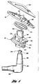
- Figures 1 through 3 show an assembly 10 according to the present invention for mounting a sun visor 12 to the roof 14 of a motor vehicle.
- the assembly comprises a frame 16, an arm receiver 18, and a coil compression spring 20.
- the frame 16 is preferably generally triangular, and has a coaxially aligned, generally triangular opening 22 therethrough defined by a raised inner perimeter 24.
- a plurality of anti-rotation anchors 26 are disposed around the perimeter 24 of the frame opening 22, preferably arranged with one anchor in each of the three corners of the perimeter.
- the anti-rotation anchors 26 project generally upwardly from the perimeter of the frame opening 22, and are adapted to engage with a snap fit the border of a matching triangular hole cut through the inner sheet metal 28 of the vehicle roof 14. Additionally, the anchors 26 serve as a means of holding a headliner 29 in place against the inner sheet metal 28.
- a plurality of rotation stop tabs 30 are similarly disposed around the perimeter 24 of the frame opening 22, preferably arranged with one stop tab in the middle of each of the three sides of the perimeter.
- the stop tabs 30 project into the frame opening 22 to cooperate with channels in the arm receiver 18, as described below.
- the arm receiver 18 has an upper flange or sheet metal lock 32, a plurality of channels 34 formed therein, and a lower flange or spring seat 36.
- the upper flange 32 is sized and shaped closely to the frame opening 22 so as to just be insertable therethrough.
- the channels 34 each include a tab receiver portion 38 opening through the upper flange 32, a lateral groove portion 40 which is preferably partially defined by a middle flange 42, and a tab stop portion 44.
- Each channel 34 is adapted to receive a corresponding rotation stop tab 30 when the upper flange 32 is inserted through the frame opening 22.
- the spring 20 is disposed between the frame 16 and the lower flange 36 of the arm receiver 18 to bias these components away from each other.
- the rotation stop tabs 30 enter a corresponding and preferably aligned tab receiver portion 38.
- the arm receiver 18 is thereafter rotated in a counterclockwise direction as viewed from below about a central axis extending generally perpendicular to the upper face of the upper flange 32, preferably about 60 degrees so that the three points of the upper flange 32 are exactly offset from the corners of the frame opening 22, the stop tabs 30 travel through the lateral groove portions 40 until they abut the tab stops 44.
- the stop tabs 30 are drawn upwardly in the tab stops 44 and held therein against the lower face of the upper flange 32 to prevent the arm receiver 18 from being withdrawn directly through the frame opening 22.
- the arm receiver can be removed from the roof of the vehicle by simply reversing the installation process, also without the aid of tools.
- a bore 46 in the arm receiver 18 is provided to receive with an interference fit a shorter vertical arm 48 of a visor pivot rod 50 of the sun visor 12.
- An irregularly shaped knob 54 disposed at the upper end of the vertical arm 48 extends, when the visor arm is fully inserted into the bore 46, through a similarly shaped opening 56 and out the top of the arm receiver 18.
- the knob 54 is preferably formed in a modified "D" shape having a four flat sides 58 so that the arm can rotate against only the friction produced by the fit with the bore 46 through all 360 degrees of a full circle, or at least a significant portion of a full circle, without coming back to a point where the pivot rod 50 is at risk of falling out of the arm receiver 18.
- An optional back plate 60 may be provided engaged with the anchors 26 of the frame 16 for shipment of the bracket subassembly, or for added rigidity when the frame is subassembled with the headliner 29 before installation into the vehicle.
- the arm receiver 18 and the visor pivot rod 50 may be separately assembled and installed into the visor as received by the customer before union with the frame.
- the back plate 60 is therefore preferably generally triangular in shape, and is formed from rigid plastic or cardboard. Typically, however, the back plate 60 is not necessary when the frame is installed into a vehicle to which the headliner has already been integrated.
- FIG. 4 shows an alternative embodiment of the apparatus 10 which is adapted to be mounted to the headliner at a location not parallel to the horizontal.
- the flanges and channels of the arm receiver 18 are situated at the anticipated angle of the headliner so that the arm 48 of the visor pivot rod 50 will nevertheless depend generally vertically.
- This embodiment also shows a modified design of the knob 54 having only a single flattened surface 58, as well as a concealment channel 62 which is optionally provided in the pivot rod 50 through which a wire may be run for supplying electrical power to visor components such as a lighted vanity mirror.
Landscapes
- Engineering & Computer Science (AREA)
- Mechanical Engineering (AREA)
- Arrangements Of Lighting Devices For Vehicle Interiors, Mounting And Supporting Thereof, Circuits Therefore (AREA)
- Connection Of Plates (AREA)
Claims (13)
- Baugruppe (10) zum Montieren einer Sonnenblende (12) an der Decke (14) eines Kraftfahrzeugs, wobei die Baugruppe einen Rahmen (16) mit einer durch ihn hindurchgehenden Öffnung (22) und wenigstens einer Verankerung (26), die ausgeführt ist, um mit der Decke in Eingriff zu kommen, und eine Armaufnahme (18) mit einem unteren Flansch (36) und einem oberen Flansch (32) aufweist, der ausgeführt ist, um durch die Rahmenöffnung gesteckt zu werden, dadurch gekennzeichnet, dass: der Rahmen wenigstens einen Anschlag (30) hat, der am Rand der Rahmenöffnung (22) angeordnet ist; die Armaufnahme (18) wenigstens eine Rinne (34) hat, die zum Aufnehmen des wenigstens einen Anschlags (30) ausgeführt ist, und eine Feder (20) zwischen dem Rahmen und der Armaufnahme angeordnet ist, um die Armaufnahme (18) normalerweise vom Rahmen (16) weg vorzuspannen, so dass nach dem Einstecken des oberen Flanschs der Armaufnahme (18) durch die Rahmenöffnung (22) und dem Drehen der Armaufnahme (18) um eine Mittelachse der wenigstens eine Drehungsanschlag (30) unter der Vorspannung der Feder (20) in die wenigstens eine Rinne (34) eindringt und durch sie hindurchbewegt wird und in ihr gehalten wird, um zu verhindern, dass die Armaufnahme (18) durch die Rahmenöffnung (22) abgezogen wird.
- Baugruppe nach Anspruch 1, bei der der Rahmen (16) allgemein dreieckig ist.
- Baugruppe nach Anspruch 1, bei der die Armöffnung (22) [sic] allgemein dreieckig ist.
- Baugruppe nach Anspruch 1, bei der um den Rand der Rahmenöffnung (22) herum eine Mehrzahl von Verankerungen (26) zum Eingriff in die Decke angeordnet ist.
- Baugruppe nach Anspruch 4, bei der die Verankerungen (26) vom Rand der Rahmenöffnung (22) allgemein nach oben ragen.
- Baugruppe nach Anspruch 4, bei der die Verankerungen (26) ausgeführt sind, um sich durch ein Loch in der Fahrzeugdecke hindurch zu erstrecken.
- Baugruppe nach Anspruch 1, bei der eine Mehrzahl von Anschlägen (30) um den Rand der Rahmenöffnung (22) herum angeordnet ist.
- Baugruppe nach Anspruch 7, bei der die Anschläge (30) in die Rahmenöffnung (22) hineinragen.
- Baugruppe nach Anspruch 7, bei der in die Armaufnahme (18) eine Anzahl von Rinnen (34) eingeformt und ausgeführt sind, um jeweils einen entsprechenden einer Mehrzahl von Anschlägen (30) aufzunehmen.
- Baugruppe nach Anspruch 1, bei der die Feder zwischen dem Rahmen (16) und dem unteren Flansch (36) der Armaufnahme (18) angeordnet ist.
- Baugruppe nach Anspruch 1, bei der die Armaufnahme eine Bohrung (46) hat, die zum Aufnehmen eines Arms (48) der Sonnenblende ausgeführt ist.
- Baugruppe nach Anspruch 11, bei der der Arm der Sonnenblende (ein) Mittel zum Halten des Arms (48) in der Bohrung (46) aufweist.
- Baugruppe nach Anspruch 12, bei der das Mittel zum Halten des Arms (48) einen ungleichförmigen Knopf (54) umfasst, der an einem oberen Ende des Arms (48) der Sonnenblende angeordnet ist.
Applications Claiming Priority (3)
| Application Number | Priority Date | Filing Date | Title |
|---|---|---|---|
| US08/199,824 US5451022A (en) | 1994-02-22 | 1994-02-22 | Mounting bracket for a sun visor |
| US199824 | 1994-02-22 | ||
| PCT/US1995/002132 WO1995022468A1 (en) | 1994-02-22 | 1995-02-21 | Mounting bracket for a sun visor |
Publications (3)
| Publication Number | Publication Date |
|---|---|
| EP0746476A1 EP0746476A1 (de) | 1996-12-11 |
| EP0746476A4 EP0746476A4 (de) | 1997-04-16 |
| EP0746476B1 true EP0746476B1 (de) | 2000-04-26 |
Family
ID=22739180
Family Applications (1)
| Application Number | Title | Priority Date | Filing Date |
|---|---|---|---|
| EP95911830A Expired - Lifetime EP0746476B1 (de) | 1994-02-22 | 1995-02-21 | Halterungsstange für sonnenblende |
Country Status (6)
| Country | Link |
|---|---|
| US (1) | US5451022A (de) |
| EP (1) | EP0746476B1 (de) |
| CA (1) | CA2183885A1 (de) |
| DE (1) | DE69516509T2 (de) |
| MX (1) | MX9603544A (de) |
| WO (1) | WO1995022468A1 (de) |
Cited By (1)
| Publication number | Priority date | Publication date | Assignee | Title |
|---|---|---|---|---|
| US6817583B2 (en) | 2002-09-18 | 2004-11-16 | Lear Corporation | Interior trim attachment apparatus and method for a vehicle |
Families Citing this family (15)
| Publication number | Priority date | Publication date | Assignee | Title |
|---|---|---|---|---|
| GB9420335D0 (en) * | 1994-10-08 | 1995-03-08 | Pilkington Perkin Elmer Ltd | Locking device |
| US5752853A (en) * | 1995-12-13 | 1998-05-19 | United Technologies Automotive Systems, Inc. | Snap-in visor mount and electrical connectors for visor mounts |
| US5829817A (en) * | 1996-09-19 | 1998-11-03 | Trw Inc. | Vehicle sunshade mounting fastener |
| WO1998042525A1 (en) * | 1997-03-26 | 1998-10-01 | Lear Corporation | Mounting bracket for a sun visor |
| US6003928A (en) * | 1997-10-14 | 1999-12-21 | Lear Automotive Dearborn, Inc. | Interior trim attachment apparatus for an automotive vehicle |
| US6494521B2 (en) * | 1999-04-16 | 2002-12-17 | William J. Hennessey | Head impact energy absorbing sun visor pivot rod connection interface cover |
| JP2000301945A (ja) * | 1999-04-20 | 2000-10-31 | Nifco Inc | サンバイザーの保持装置 |
| US7168138B2 (en) | 2000-03-27 | 2007-01-30 | Newfrey Llc | Resilient clip fastener |
| EP1256471B1 (de) * | 2001-05-11 | 2007-02-14 | Yazaki Corporation | Haltekonsolen-Struktur für Sonnenblenden |
| US6511116B1 (en) * | 2001-07-06 | 2003-01-28 | Toyota Technical Center, Usa, Inc. | Mounting bracket for vehicle visor and method of mounting bracket and visor in a vehicle |
| KR100419116B1 (ko) * | 2001-10-18 | 2004-02-18 | 기아자동차주식회사 | 차량의 선바이저 조립구조 |
| US6659527B1 (en) * | 2002-09-18 | 2003-12-09 | Lear Corporation | Interior trim attachment apparatus and method for a vehicle |
| US8091946B2 (en) * | 2008-06-17 | 2012-01-10 | Irvin Automotive Products, Inc. | Screwless visor mount assembly |
| US8020914B2 (en) * | 2009-07-23 | 2011-09-20 | International Truck Intellectual Property Company, Llc | Visor support and method |
| US9604580B2 (en) * | 2015-06-19 | 2017-03-28 | Rosemount Aerospace, Inc. | Tool-less low profile rotation mount |
Family Cites Families (25)
| Publication number | Priority date | Publication date | Assignee | Title |
|---|---|---|---|---|
| US2357974A (en) * | 1939-07-13 | 1944-09-12 | Gordon A Roberts | Visor |
| US2939741A (en) * | 1956-10-25 | 1960-06-07 | Gen Motors Corp | Sunshade support assembly |
| US3017217A (en) * | 1960-01-26 | 1962-01-16 | Gen Motors Corp | Sunshade support assembly |
| GB1251479A (de) * | 1970-06-20 | 1971-10-27 | ||
| US4023856A (en) * | 1976-04-02 | 1977-05-17 | American Motors Corporation | Vehicle sun shield |
| DE2653988B2 (de) * | 1976-11-27 | 1978-09-07 | Gebr. Happich Gmbh, 5600 Wuppertal | Sonnenblende für Kraftfahrzeuge |
| FR2478550A1 (fr) * | 1980-03-21 | 1981-09-25 | Mecanismes Comp Ind De | Dispositif de montage d'une bras de support et d'articulation de pare-soleil de vehicule |
| US4569552A (en) * | 1984-10-04 | 1986-02-11 | Prince Corporation | Visor mounting assembly |
| US4653708A (en) * | 1985-12-16 | 1987-03-31 | Hamilton Standard Controls, Inc. | Twist-in mounting for a thermostat |
| DE3601762C1 (de) * | 1986-01-22 | 1987-04-30 | Happich Gmbh Gebr | Sonnenblende fuer Fahrzeuge |
| US4729590A (en) * | 1987-03-23 | 1988-03-08 | Prince Corporation | Visor rod mount |
| DE3730346A1 (de) * | 1987-09-10 | 1989-03-30 | Ver Glaswerke Gmbh | Glasscheibe fuer ein kraftfahrzeug |
| US4858983A (en) * | 1988-04-04 | 1989-08-22 | White Jay E | Sun visor frame and mounting structure |
| US5082323A (en) * | 1988-06-10 | 1992-01-21 | Dowd James D | Sunshade fastener module for use with modular headliner |
| US4902068A (en) * | 1988-06-10 | 1990-02-20 | United Technologies Automotive, Inc. | Modular headliner assembly |
| US5061005A (en) * | 1989-08-16 | 1991-10-29 | Prince Corporation | Snap-in visor mount |
| US4989911A (en) * | 1989-08-16 | 1991-02-05 | Prince Corporation | Snap-in visor mount |
| US5056853A (en) * | 1989-08-16 | 1991-10-15 | Prince Corporation | Snap-in visor mount |
| US5201564A (en) * | 1989-08-16 | 1993-04-13 | Prince Corporation | Snap-in visor mount |
| US5044685A (en) * | 1989-10-18 | 1991-09-03 | Yang Pai Sung | Sun visor system |
| US5062608A (en) * | 1990-04-23 | 1991-11-05 | Chivas Products Limited | Visor mount |
| US5054839A (en) * | 1990-08-31 | 1991-10-08 | White Jay E | Vehicular sun visor assembly |
| US5031954A (en) * | 1990-10-29 | 1991-07-16 | Van Dresser Corporation | Mounting bracket and arm assembly for a vehicle sunshade and method of installing same in a vehicle |
| US5082322A (en) * | 1991-02-28 | 1992-01-21 | Prince Corporation | Visor rod mount |
| US5098151A (en) * | 1991-04-05 | 1992-03-24 | Crotty Corporation | Automotive sunshade mounting bracket |
-
1994
- 1994-02-22 US US08/199,824 patent/US5451022A/en not_active Expired - Lifetime
-
1995
- 1995-02-21 CA CA002183885A patent/CA2183885A1/en not_active Abandoned
- 1995-02-21 EP EP95911830A patent/EP0746476B1/de not_active Expired - Lifetime
- 1995-02-21 WO PCT/US1995/002132 patent/WO1995022468A1/en not_active Ceased
- 1995-02-21 DE DE69516509T patent/DE69516509T2/de not_active Expired - Fee Related
-
1996
- 1996-08-21 MX MX9603544A patent/MX9603544A/es not_active IP Right Cessation
Cited By (2)
| Publication number | Priority date | Publication date | Assignee | Title |
|---|---|---|---|---|
| US6817583B2 (en) | 2002-09-18 | 2004-11-16 | Lear Corporation | Interior trim attachment apparatus and method for a vehicle |
| DE10301662B4 (de) * | 2002-09-18 | 2005-05-25 | Lear Corp., Southfield | Montagebaueinheit und Verfahren zum Befestigen einer Sonnenblende in einem Fahrzeug |
Also Published As
| Publication number | Publication date |
|---|---|
| DE69516509D1 (de) | 2000-05-31 |
| US5451022A (en) | 1995-09-19 |
| EP0746476A4 (de) | 1997-04-16 |
| WO1995022468A1 (en) | 1995-08-24 |
| EP0746476A1 (de) | 1996-12-11 |
| MX9603544A (es) | 1998-01-31 |
| DE69516509T2 (de) | 2000-09-21 |
| CA2183885A1 (en) | 1995-08-24 |
Similar Documents
| Publication | Publication Date | Title |
|---|---|---|
| EP0746476B1 (de) | Halterungsstange für sonnenblende | |
| EP1007381B1 (de) | Schnappbefestigung | |
| WO1995022468A9 (en) | Mounting bracket for a sun visor | |
| US5645308A (en) | Sliding visor | |
| US4569552A (en) | Visor mounting assembly | |
| US4500131A (en) | Visor control | |
| US5409285A (en) | Sliding visor | |
| US4981322A (en) | Assist strap for a motor vehicle | |
| US6179366B1 (en) | Sunshade mounting clip assembly | |
| US5314227A (en) | Bezel locking visor mount | |
| US4690450A (en) | Visor system | |
| US5331525A (en) | Low profile sun visor system with remote lighting | |
| US6547308B2 (en) | Visor mounting assembly | |
| MXPA96003544A (en) | Mounting clamp for an anti visor | |
| US4762359A (en) | Visor system | |
| US6015126A (en) | Triangular snap-in mount | |
| US6817583B2 (en) | Interior trim attachment apparatus and method for a vehicle | |
| EP1379400B1 (de) | Sonnenblenden-clip | |
| US5967589A (en) | Sun visor retention clip | |
| EP0126825A1 (de) | Sonnenblendeneinheit | |
| US6719352B2 (en) | Visor mounting assembly | |
| US5765898A (en) | Vehicle sunshade mounting assembly | |
| US6659527B1 (en) | Interior trim attachment apparatus and method for a vehicle | |
| KR100328984B1 (ko) | 자동차의 선 바이저 | |
| JPH0248242Y2 (de) |
Legal Events
| Date | Code | Title | Description |
|---|---|---|---|
| PUAI | Public reference made under article 153(3) epc to a published international application that has entered the european phase |
Free format text: ORIGINAL CODE: 0009012 |
|
| 17P | Request for examination filed |
Effective date: 19960909 |
|
| AK | Designated contracting states |
Kind code of ref document: A1 Designated state(s): DE FR GB IT SE |
|
| A4 | Supplementary search report drawn up and despatched |
Effective date: 19970224 |
|
| AK | Designated contracting states |
Kind code of ref document: A4 Designated state(s): DE FR GB IT SE |
|
| RAP1 | Party data changed (applicant data changed or rights of an application transferred) |
Owner name: AUTOMOTIVE INDUSTRIES MANUFACTURING, INC. |
|
| RAP1 | Party data changed (applicant data changed or rights of an application transferred) |
Owner name: LEAR CORPORATION |
|
| 17Q | First examination report despatched |
Effective date: 19980803 |
|
| GRAG | Despatch of communication of intention to grant |
Free format text: ORIGINAL CODE: EPIDOS AGRA |
|
| GRAG | Despatch of communication of intention to grant |
Free format text: ORIGINAL CODE: EPIDOS AGRA |
|
| GRAH | Despatch of communication of intention to grant a patent |
Free format text: ORIGINAL CODE: EPIDOS IGRA |
|
| GRAH | Despatch of communication of intention to grant a patent |
Free format text: ORIGINAL CODE: EPIDOS IGRA |
|
| GRAA | (expected) grant |
Free format text: ORIGINAL CODE: 0009210 |
|
| ITF | It: translation for a ep patent filed | ||
| AK | Designated contracting states |
Kind code of ref document: B1 Designated state(s): DE FR GB IT SE |
|
| REF | Corresponds to: |
Ref document number: 69516509 Country of ref document: DE Date of ref document: 20000531 |
|
| ET | Fr: translation filed | ||
| PG25 | Lapsed in a contracting state [announced via postgrant information from national office to epo] |
Ref country code: SE Free format text: LAPSE BECAUSE OF NON-PAYMENT OF DUE FEES Effective date: 20010222 |
|
| PLBE | No opposition filed within time limit |
Free format text: ORIGINAL CODE: 0009261 |
|
| STAA | Information on the status of an ep patent application or granted ep patent |
Free format text: STATUS: NO OPPOSITION FILED WITHIN TIME LIMIT |
|
| 26N | No opposition filed | ||
| EUG | Se: european patent has lapsed |
Ref document number: 95911830.8 |
|
| PG25 | Lapsed in a contracting state [announced via postgrant information from national office to epo] |
Ref country code: FR Free format text: LAPSE BECAUSE OF NON-PAYMENT OF DUE FEES Effective date: 20011031 |
|
| REG | Reference to a national code |
Ref country code: FR Ref legal event code: ST |
|
| REG | Reference to a national code |
Ref country code: GB Ref legal event code: IF02 |
|
| PGFP | Annual fee paid to national office [announced via postgrant information from national office to epo] |
Ref country code: GB Payment date: 20040218 Year of fee payment: 10 |
|
| PGFP | Annual fee paid to national office [announced via postgrant information from national office to epo] |
Ref country code: DE Payment date: 20040331 Year of fee payment: 10 |
|
| PG25 | Lapsed in a contracting state [announced via postgrant information from national office to epo] |
Ref country code: IT Free format text: LAPSE BECAUSE OF NON-PAYMENT OF DUE FEES;WARNING: LAPSES OF ITALIAN PATENTS WITH EFFECTIVE DATE BEFORE 2007 MAY HAVE OCCURRED AT ANY TIME BEFORE 2007. THE CORRECT EFFECTIVE DATE MAY BE DIFFERENT FROM THE ONE RECORDED. Effective date: 20050221 Ref country code: GB Free format text: LAPSE BECAUSE OF NON-PAYMENT OF DUE FEES Effective date: 20050221 |
|
| PG25 | Lapsed in a contracting state [announced via postgrant information from national office to epo] |
Ref country code: DE Free format text: LAPSE BECAUSE OF NON-PAYMENT OF DUE FEES Effective date: 20050901 |
|
| GBPC | Gb: european patent ceased through non-payment of renewal fee |
Effective date: 20050221 |