EP0745508B1 - Method for making a seat back frame of an automotive vehicle - Google Patents
Method for making a seat back frame of an automotive vehicle Download PDFInfo
- Publication number
- EP0745508B1 EP0745508B1 EP96107521A EP96107521A EP0745508B1 EP 0745508 B1 EP0745508 B1 EP 0745508B1 EP 96107521 A EP96107521 A EP 96107521A EP 96107521 A EP96107521 A EP 96107521A EP 0745508 B1 EP0745508 B1 EP 0745508B1
- Authority
- EP
- European Patent Office
- Prior art keywords
- profile section
- cross
- sectional area
- bent
- backrest
- Prior art date
- Legal status (The legal status is an assumption and is not a legal conclusion. Google has not performed a legal analysis and makes no representation as to the accuracy of the status listed.)
- Expired - Lifetime
Links
Images


Classifications
-
- B—PERFORMING OPERATIONS; TRANSPORTING
- B60—VEHICLES IN GENERAL
- B60N—SEATS SPECIALLY ADAPTED FOR VEHICLES; VEHICLE PASSENGER ACCOMMODATION NOT OTHERWISE PROVIDED FOR
- B60N2/00—Seats specially adapted for vehicles; Arrangement or mounting of seats in vehicles
- B60N2/68—Seat frames
-
- H—ELECTRICITY
- H04—ELECTRIC COMMUNICATION TECHNIQUE
- H04L—TRANSMISSION OF DIGITAL INFORMATION, e.g. TELEGRAPHIC COMMUNICATION
- H04L27/00—Modulated-carrier systems
- H04L27/26—Systems using multi-frequency codes
- H04L27/2601—Multicarrier modulation systems
- H04L27/2626—Arrangements specific to the transmitter only
- H04L27/26265—Arrangements for sidelobes suppression specially adapted to multicarrier systems, e.g. spectral precoding
Definitions
- the invention relates to a method for manufacturing one consisting of two longitudinal spars and a cross spar, approximately U-shaped frame of a backrest of a motor vehicle seat, in which the longitudinal spars from an originally straight, band-like flat strand or roller profile with over its length of constant cross-sectional area are formed (See e.g. DE-A-43 155 21).
- Backrest frames of motor vehicle seats normally exist made of metal and have the shape of one on the head standing U.
- the legs of the U are in the following as Longitudinal spars referred to, the base piece as a cross spar.
- the backrest frame is used for frontal impacts (from the rear or from the front) most heavily on the vehicle if the person using the seat with torso and head against the backrest and headrest is thrown.
- DE-A-43 155 21 is a manufacturing process one consisting of two longitudinal spars and a cross spar, approximately U-shaped frame of a backrest of a motor vehicle known in which the longitudinal spars from an original straight, band-like flat extruded profile with over his Length of constant cross-sectional area are formed and weak and strong areas are provided in a symmetrical arrangement are.
- This method continues to claim the claimed Cross-sectional areas around in the weak areas horizontal bending axes bent by about 90 °.
- the object underlying the invention is in contrast, in a method of the type mentioned with which it is possible to create the cross-sectional area of the profile part from which the longitudinal spars and the cross spar exists to the expected at the respective places Adjust maximum load.
- this object is achieved by that on a strong central zone across the width of the profile part going cross-sectional area of the profile part which the longitudinal spars are formed on both sides weak area and a subsequent strong one follow the area so that the profile is trimmed so that its Width continuously with increasing distance from both ends decreases, and that with respect to the strong central zone external cross-sectional areas of the profile cross-sectional area around bending axes, which are in the weak areas lie to be bent by about 90 °.
- the profile cross-sectional area exists from a strong central zone 3, adjoining it weaker areas 4 and subsequent stronger areas 5.
- the width of the central zone 3 must be big enough so that the bolt circle 10, with the help of it the backrest frame over rivets or screws and joint pieces attached to the seat frame, find space on it can.
- the width of the weaker profile areas 4 is approximately equal to half the difference in width between the widest Set the longitudinal bars 1 and the cross bar 2 in the towards the backrest level normal direction.
- the longitudinal areas of the profile piece, the width of decreases continuously at both ends correspond to the lengths of the longitudinal bars 1. From the outside strong profile zones 5 are strong in the area of Bending claimed lower ends of the longitudinal spars 1 from farthest away from the central, neutral zone lying areas formed. Doing so in these areas achieved good bending stiffness with low weight.
- the strong central zone 3 of the cross-sectional area of the profile piece enables the backrest frame and the headrest bracket without impermissibly high surface pressures on the backrest caused by the fasteners.
- the strong middle zone 3 can also be used as something higher profile zone with a hollow chamber with an approximately rectangular shape Cross-sectional area to be executed. This allows the Flexural rigidity of the backrest frame around bending axes, which lie normal to the backrest level.
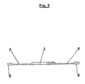
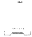
- Area of the cross bar 2 at least on the front the back frame side of the profile surface of the weak area 4 and the subsequent strong one Area 5 is not removed, but at two, on the two Profiles parallel to the edges of the weak area bent in the same direction by about 90 ° so that the weak area 4 comes to lie parallel to the backrest plane and the strong area 5 under the strong middle zone 3 (Fig. 4, Fig. 7, Fig. 8).
- This design is the attachment of headrest brackets - with which it must be possible to apply large torsional moments in the cross member initiate - relieved.
- a possible design for it, being an additional holding part 11 is used is in Fig. 8 outlines.
Landscapes
- Engineering & Computer Science (AREA)
- Physics & Mathematics (AREA)
- Spectroscopy & Molecular Physics (AREA)
- Computer Networks & Wireless Communication (AREA)
- Signal Processing (AREA)
- Aviation & Aerospace Engineering (AREA)
- Transportation (AREA)
- Mechanical Engineering (AREA)
- Chair Legs, Seat Parts, And Backrests (AREA)
- Extrusion Moulding Of Plastics Or The Like (AREA)
- Seats For Vehicles (AREA)
Description
Die Erfindung betrifft ein Verfahren zur Herstellung eines aus zwei Längsholmen und einem Querholm bestehenden, etwa U-förmigen Rahmens einer Lehne eines Kraftfahrzeugsitzes, bei welchem die Längsholme aus einem ursprünglich geraden, bandartig flachen Strang- oder Walzenprofil mit über seine Länge konstanter Querschnittsfläche gebildet werden (Siehe z.B. DE-A-43 155 21).The invention relates to a method for manufacturing one consisting of two longitudinal spars and a cross spar, approximately U-shaped frame of a backrest of a motor vehicle seat, in which the longitudinal spars from an originally straight, band-like flat strand or roller profile with over its length of constant cross-sectional area are formed (See e.g. DE-A-43 155 21).
Lehnenrahmen von Kraftfahrzeugsitzen bestehen im Normalfall aus Metall und haben die Form eines auf dem Kopf stehenden U. Die Schenkel des U werden im Folgenden als Längsholme bezeichnet, das Basisstück als Querholm.Backrest frames of motor vehicle seats normally exist made of metal and have the shape of one on the head standing U. The legs of the U are in the following as Longitudinal spars referred to, the base piece as a cross spar.
Der Lehnenrahmen wird bei frontalen Stößen (von hinten oder von vorne) auf das Fahrzeug am stärksten belastet, wenn die den Sitz benützende Person mit Rumpf und Kopf gegen Lehne und Kopfstütze geschleudert wird.The backrest frame is used for frontal impacts (from the rear or from the front) most heavily on the vehicle if the person using the seat with torso and head against the backrest and headrest is thrown.
Die größten Belastungen treten an den Verbindungsstellen zwischen Lehnenrahmen und Fahrzeugsitz sowie an den Verbindungsstellen zwischen Lehnenrahmen und Kopfstütze auf. Diese Belastungen sind Biegemomente um eine waagrechte, quer zur Fahrtrichtung liegende Achse. An den Enden der Längsholme ist der Lehnenrahmen auf Biegung beansprucht, an den Stellen der Kopfstützenbefestigung auf Torsion.The greatest stresses occur at the connection points between the backrest frame and vehicle seat and at the connection points between the backrest frame and the headrest. These loads are bending moments around a horizontal, transverse axis to the direction of travel. At the ends of the longitudinal spars the backrest frame is subjected to bending on the Set the headrest attachment to torsion.
Im Sinne des Leichtbaues sollte das den Lehnenrahmen bildende Metallteil an allen Stellen eine der standzuhaltenden Maximalbelastung angepaßte Querschnittsfläche aufweisen.In the sense of lightweight construction, this should be the backrest frame forming metal part at all points one of the to be withstood Have the maximum load adapted cross-sectional area.
Bei den häufig verwendeten Lehnenrahmen, welche aus einem gebogenen Rundrohr gebildet werden, tritt in diesem Sinne der Nachteil auf, daß die durch die Stellen größter Belastung bedingte Mindestquerschnittsfläche auch an jenen Stellen beibehalten werden muß, an denen niemals eine große Belastung auftritt.With the frequently used backrest frames, which consist of one bent round tube are formed in this sense The disadvantage is that the greatest stress due to the places conditional minimum cross-sectional area also in those places must be maintained on which never a great burden occurs.
Bei Rahmen, welche als Magnesium-Druckgußteil gefertigt werden, ist eine gute Anpassung der Querschnittsfläche an die zu erwartende Belastung möglich. Begrenzungen ergeben sich durch die gießtechnisch bedingte Mindestwandstärke des Bauteiles. Nachteilig sind auch die hohen Kosten der Gießform, der hohe Materialpreis, die geringe Duktilität (geringe Bruchdehnung) von Gußlegierungen und der erforderliche hohe Aufwand zur Vermeidung bzw. Erkennung von Gießfehlern wie Lunkern oder Poren.For frames made as a magnesium die-cast part is a good adjustment to the cross-sectional area the expected load is possible. Limitations the minimum wall thickness of the Component. Another disadvantage is the high cost of the mold, the high material price, the low ductility (low Elongation at break) of cast alloys and the required high effort to avoid or detect casting errors such as cavities or pores.
Bei Rahmen, welche aus gefalteten und gebogenen Blechen gebildet werden, ergeben sich Begrenzungen dadurch, daß die Bleche an allen Stellen die gleiche Dicke haben. Eine große Blechdicke ist aber nur an den Verbindungsstellen des Lehnenrahmens mit dem Sitzrahmen und den Kopfstützenbügeln sowie in den auf Biegung beanspruchten Zonen an den von der neutralen Faser weit entfernt liegenden Querschnittsbereichen erwünscht. An allen anderen Stellen wäre eine kleinere Blechstärke erwünscht, da dort nie eine große Belastung auftritt.For frames made of folded and bent sheets are formed, limitations result from the fact that the Sheets have the same thickness at all points. A big Sheet thickness is only at the joints of the backrest frame with the seat frame and headrest brackets as well in the areas subject to bending at the neutral fiber cross-sectional areas far away he wishes. In all other places there would be a smaller one Sheet thickness is desirable because there is never a lot of stress.
Aus der o.g. DE-A-43 155 21 ist ein Verfahren zur Herstellung eines aus zwei Längsholmen und einem Querholm bestehenden, etwa U-förmigen Rahmens einer Lehne eines Kraftfahrzeuges bekannt, bei dem die Längsholme aus einem ursprünglich geraden, bandartig flachen Strangpreßprofil mit über seine Länge konstanter Querschnittsfläche gebildet werden und schwache und starke Bereiche in symmetrischer Anordnung vorgesehen sind. Bei diesem Verfahren werden weiterhin die beanspruchten Querschnittsbereiche um in den schwachen Bereichen liegende Biegeachsen um etwa 90° gebogen.From the above DE-A-43 155 21 is a manufacturing process one consisting of two longitudinal spars and a cross spar, approximately U-shaped frame of a backrest of a motor vehicle known in which the longitudinal spars from an original straight, band-like flat extruded profile with over his Length of constant cross-sectional area are formed and weak and strong areas are provided in a symmetrical arrangement are. This method continues to claim the claimed Cross-sectional areas around in the weak areas horizontal bending axes bent by about 90 °.
Die der Erfindung zugrunde liegende Aufgabe besteht demgegenüber darin, ein Verfahren der eingangs genannten Art zu schaffen, mit dem es möglich ist, die Querschnittsfläche des Profilteils, aus dem die Längsholme und der Querholm besteht, an die an den jeweiligen Stellen jeweils zu erwartende Maximalbeanspruchung anzupassen.The object underlying the invention is in contrast, in a method of the type mentioned with which it is possible to create the cross-sectional area of the profile part from which the longitudinal spars and the cross spar exists to the expected at the respective places Adjust maximum load.
Diese Aufgabe wird gemäß der Erfindung dadurch gelöst, daß auf eine starke Mittelzone der über die Breite des Profilteils gehenden Querschnittsfläche des Profilteiles, aus welchem die Längsholme gebildet werden, beiderseits ein schwacher Bereich und ein sich daran anschließender starker Bereich folgen, daß das Profil so beschnitten wird, daß seine Breite mit steigender Entfernung von beiden Enden kontinuierlich abnimmt, und daß bezüglich der starken Mittelzone außenliegende Querschnittsbereiche der Profilquerschnittsfläche um Biegeachsen, welche in den schwachen Bereichen liegen, um etwa 90° gebogen werden.According to the invention, this object is achieved by that on a strong central zone across the width of the profile part going cross-sectional area of the profile part which the longitudinal spars are formed on both sides weak area and a subsequent strong one Follow the area so that the profile is trimmed so that its Width continuously with increasing distance from both ends decreases, and that with respect to the strong central zone external cross-sectional areas of the profile cross-sectional area around bending axes, which are in the weak areas lie to be bent by about 90 °.
Besonders bevorzugte Weiterbildungen und Ausgestaltungen
des erfindungsgemäßen Verfahrens sind Gegenstand der
Patentansprüche 2 bis 4.Particularly preferred further developments and refinements
the inventive method are the subject of
Die Erfindung wird im Folgenden anhand der Zeichnungen
näher beschrieben:
Wie in Figur 3 ersichtlich, besteht die Profilquerschnittsfläche
aus einer starken Mittelzone 3, daran anschließenden
schwächeren Bereichen 4 und daran anschließenden
stärkeren Bereichen 5. Die Breite der Mittelzone 3 muß
genügend groß sein, damit der Lochkreis 10, mit Hilfe dessen
der Lehnenrahmen über Niete oder Schrauben und Gelenkstücken
am Sitzflächenrahmen befestigt wird, darauf Platz finden
kann. Die Breite der schwächeren Profilbereiche 4 ist etwa
gleich dem halben Unterschied der Breiten zwischen den breitesten
Stellen der Längsholme 1 und dem Querholm 2 in der
auf die Lehnenebene normalen Richtung.As can be seen in FIG. 3, the profile cross-sectional area exists
from a strong
Die Längsbereiche des Profilstückes, deren Breite von
beiden Enden her kontinuierlich abnimmt (Fig. 2, Fig. 4),
entsprechen den Längen der Längsholme 1. Aus den außen liegenden
starken Profilzonen 5 werden im Bereich der stark auf
Biegung beanspruchten unteren Enden der Längsholme 1 die von
der mittig liegenden, neutralen Zone am weitesten entfernt
liegenden Bereiche gebildet. Dadurch wird in diesen Bereichen
eine gute Biegesteifigkeit bei geringem Gewicht erreicht.The longitudinal areas of the profile piece, the width of
decreases continuously at both ends (FIG. 2, FIG. 4),
correspond to the lengths of the
Die starke Mittelzone 3 der Querschnittsfläche des Profilstückes
ermöglicht die Befestigung des Lehnenrahmens und
der Kopfstützenhalterung, ohne daß unzulässig hohe Flächenpressungen
an der Lehne durch die Befestigungselemente entstehen.
Die starke Mittelzone 3 kann auch als eine etwas
höhere Profilzone mit einer Hohlkammer mit etwa rechteckförmiger
Querschnittsfläche ausgeführt sein. Dadurch kann die
Biegesteifigkeit des Lehnenrahmens um Biegeachsen, welche
normal zur Lehnenebene liegen, erhöht werden.The strong
Gemäß einer vorteilhaften Weiterentwicklung werden im
Bereich des Querholmes 2 zumindest an der zur Vorderseite
des Lehnenrahmens hin liegenden Seite der Profilfläche der
schwache Bereich 4 und der sich daran anschließende starke
Bereich 5 nicht entfernt, sondern um zwei, an den beiden
Rändern des schwachen Bereichs liegende profilparallele Achsen
im gleichen Drehsinn um etwa 90° so gebogen, daß der
schwache Bereich 4 parallel zur Lehnenebene zu liegen kommt
und der starke Bereich 5 unter der starken Mittelzone 3
(Fig. 4, Fig. 7, Fig. 8). Dadurch wird erreicht, daß der
Lehnenrahmen in dem Bereich, an welchen im Fall eines Unfalles
der Kopf der den Sitz innehabenden Person anschlagen
kann, keine scharfen Kanten aufweist. Mit dieser Bauweise
wird die Anbringung von Kopfstützenhalterungen - mit denen
es möglich sein muß, große Torsionsmomente in den Querholm
einzuleiten - erleichtert. Ein mögliche Bauweise dafür, wobei
ein zusätzlicher Halteteil 11 verwendet wird, ist in
Fig. 8 skizziert.According to an advantageous further development in
Area of the
Als Material für den Lehnenrahmen kommen vor allem herkömmliche strangpreßbare Aluminiumknetlegierungen in Frage. Da es möglich ist, das Profilteil als Walzprofil zu fertigen, kann auch die Verwendung von Stahl in Erwägung gezogen werden.Conventional materials are the main material used for the backrest frame extrudable wrought aluminum alloys in question. Since it is possible to manufacture the profile part as a rolled profile, can also consider the use of steel become.
Bei der Herstellung entsprechend der Erfindung ergibt sich neben der Lösung der eingangs genannten Aufgabe der Vorteil, daß vom unteren Lehnenbereich zum oberen Lehnenbereich hin die auf die Lehnenebene normal liegende Dicke des Lehnenrahmens kontinuierlich abnimmt. Das kommt den Anforderungen an das Design von Lehnen sehr entgegen.In the manufacture according to the invention results in addition to solving the task mentioned at the outset Advantage that from the lower backrest area to the upper backrest area down to the normal thickness of the backrest level The backrest frame decreases continuously. That comes up to the requirements to the design of backrests.
Claims (4)
- A method for manufacturing an approximately U-shaped frame of a backrest of a motor vehicle seat consisting of two longitudinal members (1) and one transverse member (2), whereby the longitudinal members (1) are formed from an originally straight, flat strip-like extruded or rolled profile section with constant cross-sectional area over its length, characterised in that a thick central zone (3) of the of the cross-sectional area of the profile section extending across the width of the profile section part from which the longitudinal members (1) are formed is followed on each side by a thin portion (4) which in tum is followed by a thick portion (5), in that the profile section part is so trimmed that its width decreases continuously with increasing distance from each end, and in that cross-sectional areas of the profile section located outwardly with respect to the thick central zone (3) are bent through approximately 90° about bending axes located in the thin portions (4).
- A method according to Claim 1, characterised in that the bending axes about which the portions of the cross-sectional area of the profile section are bent are so located that the distance from the thick central zone (3) of the cross-sectional area of the profile section decreases with increasing distance from the wide end of the profile section in the longitudinal direction of the profile section.
- A method according to Claim 1 or 2, characterised in that the profile section part is bent to form a U-shape about axes which are perpendicular to the direction of the profile section.
- A method according to Claim 3, characterised in that in the area of the transverse member (2) the portions of the cross-sectional areas of the profile section which come to be located closer to the front face of the backrest frame with respect to the thick central zone (3) of the cross-sectional area of the profile section are each so bent in the same direction of rotation through approximately 90° about two axes lying parallel to the direction of the profile section, which axes are located at the edges of the thin portion (4), that the thin portion (4) is bent towards the centre of the plane of the backrest.
Applications Claiming Priority (3)
| Application Number | Priority Date | Filing Date | Title |
|---|---|---|---|
| AT786/95 | 1995-05-10 | ||
| AT78695 | 1995-05-10 | ||
| AT0078695A AT407502B (en) | 1995-05-10 | 1995-05-10 | METHOD FOR PRODUCING A U-SHAPED FRAME OF A REAR OF A MOTOR VEHICLE SEAT, THAT IS COMPOSED OF TWO LONGITUDE AND A CROSS-BAR |
Publications (3)
| Publication Number | Publication Date |
|---|---|
| EP0745508A2 EP0745508A2 (en) | 1996-12-04 |
| EP0745508A3 EP0745508A3 (en) | 1998-06-17 |
| EP0745508B1 true EP0745508B1 (en) | 2002-09-25 |
Family
ID=3499718
Family Applications (1)
| Application Number | Title | Priority Date | Filing Date |
|---|---|---|---|
| EP96107521A Expired - Lifetime EP0745508B1 (en) | 1995-05-10 | 1996-05-10 | Method for making a seat back frame of an automotive vehicle |
Country Status (3)
| Country | Link |
|---|---|
| EP (1) | EP0745508B1 (en) |
| AT (1) | AT407502B (en) |
| DE (1) | DE59609708D1 (en) |
Cited By (2)
| Publication number | Priority date | Publication date | Assignee | Title |
|---|---|---|---|---|
| DE102009017374A1 (en) | 2009-04-14 | 2010-10-21 | GM Global Technology Operations, Inc., Detroit | Method for producing a structural component for a motor vehicle |
| EP4321378A2 (en) | 2022-07-22 | 2024-02-14 | Bruns Holding GmbH & Co. KG | Frame for a vehicle seat and vehicle seat having such a frame |
Families Citing this family (3)
| Publication number | Priority date | Publication date | Assignee | Title |
|---|---|---|---|---|
| DE19627546C1 (en) * | 1996-07-09 | 1997-10-23 | Faure Bertrand Sitztech Gmbh | Back rest for road vehicle seat |
| DE19826732B4 (en) | 1998-06-16 | 2007-03-29 | Euromotive Ges.M.B.H. | Seatback design |
| DE10249394B4 (en) * | 2002-10-23 | 2004-09-09 | Euromotive Ges.M.B.H. & Co. Kg | Seat or backrest frame part of a seat with inclination adjuster |
Family Cites Families (4)
| Publication number | Priority date | Publication date | Assignee | Title |
|---|---|---|---|---|
| JPH0753556Y2 (en) * | 1990-11-26 | 1995-12-13 | 池田物産株式会社 | Back frame |
| US5338100A (en) * | 1992-02-24 | 1994-08-16 | Itt Corporation | High strength automotive seat frame and method |
| DE4315521C1 (en) * | 1993-05-10 | 1994-05-11 | Austria Metall | Prodn. of frame for vehicle seat - using aluminium@ profiles with ramp-type plate at front frame part forming front seat part and running inclined from back to front |
| US5499863A (en) * | 1993-05-17 | 1996-03-19 | Toyota Shatai Kabushiki Kaisha | Seat back frame |
-
1995
- 1995-05-10 AT AT0078695A patent/AT407502B/en not_active IP Right Cessation
-
1996
- 1996-05-10 DE DE59609708T patent/DE59609708D1/en not_active Expired - Lifetime
- 1996-05-10 EP EP96107521A patent/EP0745508B1/en not_active Expired - Lifetime
Cited By (2)
| Publication number | Priority date | Publication date | Assignee | Title |
|---|---|---|---|---|
| DE102009017374A1 (en) | 2009-04-14 | 2010-10-21 | GM Global Technology Operations, Inc., Detroit | Method for producing a structural component for a motor vehicle |
| EP4321378A2 (en) | 2022-07-22 | 2024-02-14 | Bruns Holding GmbH & Co. KG | Frame for a vehicle seat and vehicle seat having such a frame |
Also Published As
| Publication number | Publication date |
|---|---|
| ATA78695A (en) | 2000-08-15 |
| EP0745508A3 (en) | 1998-06-17 |
| AT407502B (en) | 2001-04-25 |
| DE59609708D1 (en) | 2002-10-31 |
| EP0745508A2 (en) | 1996-12-04 |
Similar Documents
| Publication | Publication Date | Title |
|---|---|---|
| DE4138647C2 (en) | Backrest frame for a seat | |
| DE10040824B4 (en) | Steering column support beam structure | |
| EP1478562B1 (en) | Supporting structure for vehicles, made of hollow steel profiles | |
| WO1989012563A1 (en) | Vehicle seat with a back-rest frame | |
| DE4204826A1 (en) | Motor vehicle bodywork made from hollow sections - has main sections joined together by intermediate pieces formed from extruded sections | |
| WO1992011157A1 (en) | Motor vehicle with a central pillar constituted by an extruded section | |
| DE102006052281B4 (en) | Support element for a cockpit carrier | |
| DE60218664T2 (en) | DEVICE FOR SPREADING A BOWL IN AN AIRPLANE PUMP | |
| EP2703289B1 (en) | Seat dividing device | |
| DE102009017374A1 (en) | Method for producing a structural component for a motor vehicle | |
| EP0790902B1 (en) | Process for manufacturing the frame of a back rest of a vehicle seat | |
| EP0745508B1 (en) | Method for making a seat back frame of an automotive vehicle | |
| DE2308825B2 (en) | Vehicle body | |
| DE4315521C1 (en) | Prodn. of frame for vehicle seat - using aluminium@ profiles with ramp-type plate at front frame part forming front seat part and running inclined from back to front | |
| DE19827066A1 (en) | Upper cross strut for front body section of motor vehicle | |
| DE10023506A1 (en) | Cockpit support for body of motor vehicle has transverse beam with reinforcing members constructed as closed or open hollow metal profile with length corresponding to part of length of transverse beam | |
| EP1583684B1 (en) | Longitudinal beam for a vehicle | |
| DE102014115938B4 (en) | Structural support for a motor vehicle | |
| DE102008050158A1 (en) | Frame structure for backrest of motor vehicle seat, has side bolsters and cross beams formed as hollow sections and connected with each other in merging manner such that hollow ring-like frame structure is provided | |
| DE102004004376B3 (en) | Fixing device for child seat in vehicle has fixing elements with seat traverse fixed to one end, and other end fitted to structural side component | |
| DE102021000796B4 (en) | Floor element for a shell of a passenger car | |
| DE102008009179B4 (en) | Method for producing a train-pressure strut for a vehicle body | |
| EP1946950A1 (en) | Housing, in particular for the air conditioning system of a vehicle | |
| DE10302950B4 (en) | Passenger seat for passenger vehicles | |
| EP2060438A2 (en) | Back for a motor vehicle seat |
Legal Events
| Date | Code | Title | Description |
|---|---|---|---|
| PUAI | Public reference made under article 153(3) epc to a published international application that has entered the european phase |
Free format text: ORIGINAL CODE: 0009012 |
|
| AK | Designated contracting states |
Kind code of ref document: A2 Designated state(s): DE FR IT SE |
|
| RIN1 | Information on inventor provided before grant (corrected) |
Inventor name: GARNWEIDNER, PETER |
|
| PUAL | Search report despatched |
Free format text: ORIGINAL CODE: 0009013 |
|
| AK | Designated contracting states |
Kind code of ref document: A3 Designated state(s): DE FR IT SE |
|
| 17P | Request for examination filed |
Effective date: 19981126 |
|
| 17Q | First examination report despatched |
Effective date: 20010613 |
|
| GRAG | Despatch of communication of intention to grant |
Free format text: ORIGINAL CODE: EPIDOS AGRA |
|
| GRAG | Despatch of communication of intention to grant |
Free format text: ORIGINAL CODE: EPIDOS AGRA |
|
| GRAH | Despatch of communication of intention to grant a patent |
Free format text: ORIGINAL CODE: EPIDOS IGRA |
|
| GRAH | Despatch of communication of intention to grant a patent |
Free format text: ORIGINAL CODE: EPIDOS IGRA |
|
| GRAA | (expected) grant |
Free format text: ORIGINAL CODE: 0009210 |
|
| AK | Designated contracting states |
Kind code of ref document: B1 Designated state(s): DE FR IT SE |
|
| REF | Corresponds to: |
Ref document number: 59609708 Country of ref document: DE Date of ref document: 20021031 |
|
| ET | Fr: translation filed | ||
| PLBE | No opposition filed within time limit |
Free format text: ORIGINAL CODE: 0009261 |
|
| STAA | Information on the status of an ep patent application or granted ep patent |
Free format text: STATUS: NO OPPOSITION FILED WITHIN TIME LIMIT |
|
| 26N | No opposition filed |
Effective date: 20030626 |
|
| PG25 | Lapsed in a contracting state [announced via postgrant information from national office to epo] |
Ref country code: IT Free format text: LAPSE BECAUSE OF NON-PAYMENT OF DUE FEES Effective date: 20050510 |
|
| PGFP | Annual fee paid to national office [announced via postgrant information from national office to epo] |
Ref country code: SE Payment date: 20080512 Year of fee payment: 13 |
|
| REG | Reference to a national code |
Ref country code: FR Ref legal event code: TP |
|
| PGRI | Patent reinstated in contracting state [announced from national office to epo] |
Ref country code: IT Effective date: 20091201 |
|
| PGFP | Annual fee paid to national office [announced via postgrant information from national office to epo] |
Ref country code: FR Payment date: 20100614 Year of fee payment: 15 |
|
| PGFP | Annual fee paid to national office [announced via postgrant information from national office to epo] |
Ref country code: IT Payment date: 20100524 Year of fee payment: 15 Ref country code: DE Payment date: 20100531 Year of fee payment: 15 |
|
| PG25 | Lapsed in a contracting state [announced via postgrant information from national office to epo] |
Ref country code: SE Free format text: LAPSE BECAUSE OF NON-PAYMENT OF DUE FEES Effective date: 20090511 |
|
| REG | Reference to a national code |
Ref country code: DE Ref legal event code: R119 Ref document number: 59609708 Country of ref document: DE |
|
| REG | Reference to a national code |
Ref country code: DE Ref legal event code: R119 Ref document number: 59609708 Country of ref document: DE |
|
| REG | Reference to a national code |
Ref country code: FR Ref legal event code: ST Effective date: 20120131 |
|
| PG25 | Lapsed in a contracting state [announced via postgrant information from national office to epo] |
Ref country code: IT Free format text: LAPSE BECAUSE OF NON-PAYMENT OF DUE FEES Effective date: 20110510 |
|
| PG25 | Lapsed in a contracting state [announced via postgrant information from national office to epo] |
Ref country code: FR Free format text: LAPSE BECAUSE OF NON-PAYMENT OF DUE FEES Effective date: 20110531 |
|
| PG25 | Lapsed in a contracting state [announced via postgrant information from national office to epo] |
Ref country code: DE Free format text: LAPSE BECAUSE OF NON-PAYMENT OF DUE FEES Effective date: 20111130 |