EP0744873A2 - Verfahren zur Datenänderungskoordinierung zwischen Telefonvermittlungsanlagen - Google Patents
Verfahren zur Datenänderungskoordinierung zwischen Telefonvermittlungsanlagen Download PDFInfo
- Publication number
- EP0744873A2 EP0744873A2 EP96303404A EP96303404A EP0744873A2 EP 0744873 A2 EP0744873 A2 EP 0744873A2 EP 96303404 A EP96303404 A EP 96303404A EP 96303404 A EP96303404 A EP 96303404A EP 0744873 A2 EP0744873 A2 EP 0744873A2
- Authority
- EP
- European Patent Office
- Prior art keywords
- switch
- message
- data
- work order
- directing
- Prior art date
- Legal status (The legal status is an assumption and is not a legal conclusion. Google has not performed a legal analysis and makes no representation as to the accuracy of the status listed.)
- Granted
Links
- 238000000034 method Methods 0.000 title claims abstract description 52
- 238000004891 communication Methods 0.000 claims abstract description 12
- 238000012546 transfer Methods 0.000 claims description 36
- 238000012545 processing Methods 0.000 claims description 18
- 230000004044 response Effects 0.000 claims description 8
- 238000009434 installation Methods 0.000 abstract description 2
- 230000000717 retained effect Effects 0.000 abstract description 2
- 230000006870 function Effects 0.000 description 4
- 238000007792 addition Methods 0.000 description 3
- 238000010586 diagram Methods 0.000 description 3
- 238000012423 maintenance Methods 0.000 description 2
- 238000013468 resource allocation Methods 0.000 description 2
- 238000012360 testing method Methods 0.000 description 2
- 238000009825 accumulation Methods 0.000 description 1
- 230000009286 beneficial effect Effects 0.000 description 1
- 239000006227 byproduct Substances 0.000 description 1
- 239000003054 catalyst Substances 0.000 description 1
- 230000009977 dual effect Effects 0.000 description 1
- 238000013519 translation Methods 0.000 description 1
Images


Classifications
-
- H—ELECTRICITY
- H04—ELECTRIC COMMUNICATION TECHNIQUE
- H04Q—SELECTING
- H04Q3/00—Selecting arrangements
- H04Q3/0016—Arrangements providing connection between exchanges
Definitions
- This invention relates to the field of telecommunications networks and, more particularly, to coordinating data changes among central office switches in such telecommunications networks.
- Transferring a customer line from one central office switch to another requires manually retrieving customer line data from a first switch and entering the same data into the memory of a second switch. If adding a new service feature is the impetus for the transfer, additional data specific to the newly added service feature must also be entered into the customer data file in the second switch. Since each central office switch typically serves one or more "blocks" of directory numbers (collectively having given office codes) wherein each block of directory numbers has a unique office code, the transfer of a customer line from one switch to another switch normally implies a directory number change.
- the prior art coordinated data exchange process is initiated by a central provisioning system which is maintained by a local exchange carrier (LEC) and serves all central office switches in a local telecommunications network.
- LEC local exchange carrier
- transferring customer line data from a first central office switch to a second central office switch requires the intervention of a service technician who receives a service work order from the central provisioning system, manually retrieves all data associated with a given customer directory number from a first central office switch and then manually installs the directory number data into a second central office switch.
- the current process for customer directory number data transfer among central office switches is exemplified by the following scenario: A customer who is currently served by an analog switch decides to set up a home office. She plans to install a facsimile machine and personal computer in her home office and determines it would be beneficial to have ISDN service on her telephone line. Accordingly, the customer contacts a service representative of her local exchange carrier and requests ISDN service. Although the customer wants ISDN service, she clearly specifies that she does not want to change her current directory number of "708-555-1234". In response to the customer's request, the service representative enters a service order to provide ISDN service to the customer line identified by the directory number "708-555-1234" into a customer service operation support system (OSS).
- OSS customer service operation support system
- the service order reaches the central provisioning system which evaluates the order and if possible (i.e. if the LEC maintains a switch capable of providing ISDN to this customer), issues a work order ticket indicating that ISDN service is to be provided to the customer line identified by the directory number "708-555-1234".
- the central office switch which serves directory number "708-555-1234" is an analog switch which is incapable of providing ISDN service.
- the LEC also maintains a digital switch (such as the 5ESS® switch sold by AT&T Network Systems) which is capable of providing ISDN service.
- the customer's line must be wired to the digital switch. Nevertheless, in accordance with the customer's request, her local directory number of "708-555-1234" and all existing features of her telephone service must not change.
- a LEC technician physically wires a new customer line from a main distributing frame to the digital central office switch, he retrieves all customer data relating to directory number "708-555-1234" stored in the analog central office switch and enters the retrieved data and the newly requested ISDN feature into the digital central office switch.
- the technician must also program a new routing index in a separate database so that incoming calls may be properly delivered to the directory number, as is known in the art.
- the technician severs the connection to the analog switch. Due to the manual retrieval and installation of data, the process is labor-intensive, time-consuming and prone to error. Therefore, there is a need in the art for automatically retrieving and installing customer data in a central office switch in response to a work order message received from a provisioning system in a local telecommunications network.
- the message directing switch is a digital switching system which includes the capability to process all work order messages issued by a central provisioning system which is maintained by a local exchange carrier. More particularly, the digital switch (which may be the "new" switch in a capping scenario) serves as a receiving point for work order messages issued by the central provisioning system. Work order messages determined by the message directing switch to be in a foreign format are delivered to another switch (i.e. the message receiving switch which may be the "old" switch in a capping scenario) for processing therein. Work order messages which require coordinated data exchanges between switches are processed under the control of the message directing switch which uses a transfer processor to carry out a data transfer protocol.
- the message directing switch formulates a data query in order to retrieve specific data from the switch acting as the message receiving switch. Once the data is received in the message directing switch, it used for normal provisioning processes. Eventually, the message directing switch directs the message receiving switch to delete the data it previously sent to the message directing switch, so that duplicate data is not maintained.
- FIGs. 1A and 1B show local telecommunications network 100 including first digital central office switch 110 which has message directing capabilities and is designated the "message directing switch".
- Two other switches namely, analog central office switch 140 and digital central office switch 170 are standard central office switches which do not possess message directing capabilities and are generally referred to as "message receiving switches".
- message directing switch 110 is the "new" switch and analog switch 140 is the "old” switch.
- Digital switch 170 is included to emphasize that any switch (analog or digital) may be a message receiving switch and that message directing switch 110 may coordinate data transfers in which digital switch 170 is the "new" switch in a capping scenario, as explained in detail below.
- an operational telecommunications network may include many more switches and that message directing switch 110 may interact with a cluster of central office switches which act as message receiving switches.
- point code converter 104 which routes incoming telephone calls from public-switched telephone network (PSTN) 102 to a central office switch in local telecommunications network 100 for those customer lines which retain directory numbers during switch change-overs.
- PSTN public-switched telephone network
- a detailed description of the operation of point code converter 104 can be found in commonly assigned U.S. patent 5,048,081 to Gavaras et al. entitled "Arrangement for Routing Packetized Messages" which issued on September 10, 1991 (hereinafter, the Gavaras et al. patent).
- Provisioning system 150 communicates with message directing switch 110 via data link 162 and in one preferred embodiment may communicate with analog switch 140 and second digital switch 170 via data link 164 and data link 174, respectively.
- Message directing switch 110 and analog switch 140 communicate with each other over intra-switch data link 166 while message directing switch 110 and second digital switch 170 communicate with each other over intra-switch data link 176.
- message directing switch 110 is a digital switch with message directing capabilities such as the 5ESS® switch manufactured and sold by AT&T Network Systems.
- Switch 110 includes three major components: an administrative module (AM) 114 which provides system wide administration, maintenance, and resource allocation; a communications module (CM) 116 which is a hub for distributing and switching voice or digital data, control information, and synchronization signals; and a plurality of switching modules (SMs) 118 and 120 which perform local switching and control functions as well as provide interfaces to customer lines A, B, C and D'.
- Remote switching module RSM 122 is similar to switching modules 118 and 120 but it serves distant customer lines E and F via a digital loop carrier (DLC) (not shown).
- DLC digital loop carrier
- Host switching module HSM 124 is the only switching module in direct communication with PSTN 102. All communication among the elements of message directing switch 110 (including communication among all SMs and between AM 114 and CM 116) is accomplished over Network Control and Time (NCT) links 125. Also shown is interface 132 which receives ported directory number routing information over message link 105 from point code converter 104 in accordance with the teaching of the Gavaras et al. patent.
- NCT Network Control and Time
- AM 114 provides system level interfaces required to operate, administer, and maintain message director switch 110.
- AM 114 comprises main processor 111, memory 113 and transfer processor 115.
- Transfer processor 115 is the interface to provisioning system 150 and controls all coordinated data provisioning functions among message directing switch 110, and analog switch 140 and digital switch 170 which act in a message receiving capacity, as described in detail below.
- Each switching module in message directing switch 110 includes a controller 127 which coordinates global functions, memory 128 for retaining specific customer line data and network element 129 for routing calls to and from individual customer lines. Consistent with connections in digital switch art, all SMs are connected by two NCT links to CM 116.
- Analog switch 140 is representative of an "old" switch in a capping scenario and includes processor 142 for global functions such as common resource allocation and maintenance control, memory 144 for storing various control programs and two switching modules SM 146 and SM 148 which serve customer lines A' B' and C' D', respectively.
- Customer line D' is connected to both SM 148 of analog switch 140 and SM 120 of message directing switch 110.
- the dual line connection of line D' indicates that this line is being transferred from analog switch 140 (the "old” switch) to message directing switch 110 (the "new switch) in a process described below.
- the digital switch 170 may be designated as the "new" switch.
- each SM in analog switch 140 includes a controller 145, memory 147 and network element 149. All communication among the elements in analog central office switch 140 is accomplished over data links 141. Also shown is interface 143 which receives routing information over message link 106 from point code converter 104 as described in the Gavaras et. al. patent.
- Digital switch 170 (shown in simple block form) includes the same elements of message directing switch 110 with the exception of transfer processor 115. Accordingly, digital switch 170 does not possess message directing capabilities but may act (as may any other switch) as a message receiving switch. Switch 170 communicates with message directing switch 110 via intra-switch data link 176, and point code converter 104 via data link 107. In one preferred embodiment, digital switch 170 is in communication with central provisioning system 150 via link 174. While message directing switch 110 is described the "new" switch, it is to be understood that digital switch 170 may serve as the "new” switch when a customer line is transferred from an analog switch (the "old” switch) to a “new” switch in a capping process. When digital switch 170 serves as the "new” switch, it continues to act as a message receiving switch in accordance with the principles of the present invention since it receives all provisioning messages relating to a coordinated data exchange from message directing switch 110.
- Provisioning system 150 includes adapter 151, CPU 152, random access memory (RAM) 154, read only memory (ROM) 156 and non-volatile database 158.
- Adapter 151 enables provisioning system 150 to receive messages from other LEC OSSs over communication link 159. Work order messages directed to message directing switch 110, analog switch 140 or digital switch 170 are also delivered via adapter 151 to the appropriate switch. Communication among the elements of provisioning system 150 is accomplished over data links 153.
- provisioning system 150 receives a service order from a customer service OSS (not shown) via communication link 159 and temporarily stores the order in RAM 154. Subsequently, CPU 152 retrieves the service order from RAM 154 and processes it using a protocol stored in ROM 156. After the service order has been processed, an appropriate work order message may be sent to central office switch 110, 140 or 170. Each work order message sent to a central office switch is categorized by directory number and retained in database 158.
- provisioning system 150 forwards all work order messages, regardless for which central office switch the message is intended, to message directing central office switch 110 for processing over data link 162.
- transfer processor 115 of switch 110 receives all work order messages from the provisioning system so that a determination may be made as to whether: the work order requires processing by message directing switch 110 only; the work order requires processing by analog switch 140 only; the work order requires processing by digital switch 170 only; the work order requires coordinated processing between message directing switch 110 and analog switch 140; the work order requires coordinated processing between message directing switch 110 and digital switch 170; or the work order requires coordinated processing between analog switch 140 and digital switch 170.
- provisioning system 150 sends work order messages which only require processing by analog switch 140 or digital switch 170 directly to the appropriate switch via data link 164 or data link 174, respectively.
- Those work order messages which require processing by message directing switch 110 only, or which require coordinated processing between message directing switch 110 and any other switch in telecommunications network 100 are delivered to message directing switch 110 over data link 162 in the manner described above.
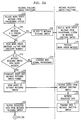
- FIG. 2 is a divided flow diagram of the method steps for controlling coordinated processing performed by message directing switch 110 serving as the "new" switch in a capping process with respect to analog switch 140 which is the "old” switch in the capping process, in response to a work order message received from provisioning system 150.
- step 202 switch 110 receives a work order message over data link 162 from provisioning system 150.
- decision step 204 transfer processor 115 makes a determination as to whether the work order message received from provisioning system 150 is in a foreign format. In this example, transfer processor 115 determines whether the work order message is in analog switch 140 or digital switch 170 format. If the outcome of step 204 is a "YES" decision, the process continues to step 206 in which the entire work order message is delivered to either switch 140 or switch 170 (i.e. a message receiving switch).
- step 208 the message receiving switch receives the work order message from switch 110 over data link 166 or data link 176 and processes the work order in step 210. (In an alternative embodiment, the message receiving switch receives the work order message directly from provisioning system 150.)
- step 211 the work order message received from provisioning system 150 is read by transfer processor 115 of message directing switch 110.
- the work order message from provisioning system 150 requires the addition of new directory number "708-555-1234" to the service base (i.e. the accumulation of all customer lines) of message directing switch 110. If the new directory number was to be added to the service base of another switch such as digital switch 170, however, switch 110 would simply facilitate a data transfer process between the switch which currently serves directory number "708-555-1234" (analog switch 140) and digital switch 170 without changing its own service base.
- transfer processor 115 makes a determination as to whether the work order message received requires a data query from another switch. Generally, all additions of directory numbers to the service base of a switch require a data query. If the outcome of decision step 212 is a "NO" decision, message directing switch 110 continues with normal provisioning in step 214. If the outcome of decision step 212 is a "YES" decision, the process continues to step 216 in which transfer processor 115 formulates a data query in the other switch format. In this example, the data query is a request for all customer data relating to directory number "708-555-1234" is formulated in analog switch 140 format, assuming that the directory number is in the analog switch's service base. The process continues to step 218 in which the data query formulated by transfer processor 115 is delivered to analog switch 140 over data link 166.
- step 220 processor 142 of analog switch 140 receives the data query from message directing switch 110.
- step 222 analog switch 140, acting in its message receiving switch capacity, finds directory number "708-555-1234" and retrieves all data relating to the directory number.
- step 224 analog switch 140 transmits the directory number data to message directing switch 110 over data link 166.
- switch 110 receives data relating to directory number "708-555-1234" from analog switch 140 and stores it in memory 113.
- the process continues (through connector A to FIG. 2B) to step 228 in which transfer processor 115 translates the data received from analog switch 140 into an appropriate switch format.
- the work order message from provisioning system 150 requires the new customer line D' to be added to the message directing switch 110 service base.
- the data received from analog switch 140 must be translated to switch 110 format. If the work order message required line D' to be added to the service base of switch 170, the translation of the data would be to digital switch 170 format.
- switch 110 uses the data received from the analog switch to process the work order message received from provisioning system 150.
- processing the work order message implies that message directing switch 110 adds new directory number "708-555-1234" and all its corresponding customer data including existing features, billing information and the recently requested ISDN service to its service base.
- processing the work order message may mean that switch 110 delivers all data corresponding to directory number "708-555-1234" over data link 176 to digital switch 170 for addition of the directory number to the digital switch 170 service base.
- step 232 message directing switch 110 sends a delete directory number "708-555-1234" message over link 166 to processor 142 of analog switch 140.
- step 234 the delete message is received by analog switch 140.
- step 236 processor 142 of analog switch 140 deletes directory number "708-555-1234" and all information relating thereto from its service base.
- step 238, analog switch 140 returns a "delete complete” message to message directing switch 110.
- step 240 message directing switch 110 receives the delete complete message.
- step 242 switch 110 reads the delete complete message from analog switch 140 and the data transfer process ends in step 244.
Landscapes
- Engineering & Computer Science (AREA)
- Computer Networks & Wireless Communication (AREA)
- Data Exchanges In Wide-Area Networks (AREA)
- Exchange Systems With Centralized Control (AREA)
- Telephonic Communication Services (AREA)
Applications Claiming Priority (2)
| Application Number | Priority Date | Filing Date | Title |
|---|---|---|---|
| US08/448,954 US5661789A (en) | 1995-05-24 | 1995-05-24 | Method for coordinating data changes among central office switches |
| US448954 | 1995-05-24 |
Publications (3)
| Publication Number | Publication Date |
|---|---|
| EP0744873A2 true EP0744873A2 (de) | 1996-11-27 |
| EP0744873A3 EP0744873A3 (de) | 1999-10-06 |
| EP0744873B1 EP0744873B1 (de) | 2003-02-26 |
Family
ID=23782296
Family Applications (1)
| Application Number | Title | Priority Date | Filing Date |
|---|---|---|---|
| EP96303404A Expired - Lifetime EP0744873B1 (de) | 1995-05-24 | 1996-05-14 | Verfahren zur Datenänderungskoordinierung zwischen Telefonvermittlungsanlagen |
Country Status (4)
| Country | Link |
|---|---|
| US (1) | US5661789A (de) |
| EP (1) | EP0744873B1 (de) |
| CA (1) | CA2172649C (de) |
| DE (1) | DE69626339D1 (de) |
Families Citing this family (6)
| Publication number | Priority date | Publication date | Assignee | Title |
|---|---|---|---|---|
| US5838783A (en) * | 1995-12-27 | 1998-11-17 | Lucent Technologies, Inc. | Smart directory management |
| US6301351B1 (en) * | 1998-04-08 | 2001-10-09 | Sbc Technology Resources Inc. | Device and method for transferring unbundled network elements between local exchange carriers |
| DE19952607B4 (de) * | 1999-11-02 | 2009-04-30 | Deutsche Telekom Ag | Verfahren und Kommunikationsnetz zum Bereitstellen eines oder mehrerer Leistungsmerkmale einem beliebigen Teilnehmer |
| US7360153B1 (en) * | 2000-01-17 | 2008-04-15 | Lucent Technologies Inc. | Method and apparatus for importing digital switching system data into a spreadsheet program |
| US7349533B2 (en) * | 2002-10-01 | 2008-03-25 | Nortel Networks Limited | Telephony transitioning system |
| EP1825705B1 (de) * | 2004-12-14 | 2016-11-16 | Telefonaktiebolaget LM Ericsson (publ) | Verfahren und vorrichtung zur steuerung eines provisionierungsprozesses in einem telekommunikationssystem |
Family Cites Families (9)
| Publication number | Priority date | Publication date | Assignee | Title |
|---|---|---|---|---|
| JPS59174061A (ja) * | 1983-03-23 | 1984-10-02 | Hitachi Ltd | オ−バレイ通信網 |
| GB2174270B (en) * | 1985-04-27 | 1988-10-12 | Stc Plc | Telecommunication system |
| US4754479A (en) * | 1986-09-17 | 1988-06-28 | American Telephone And Telegraph Company | Station number portability |
| US4899373A (en) * | 1986-11-28 | 1990-02-06 | American Telephone And Telegraph Company At&T Bell Laboratories | Method and apparatus for providing personalized telephone subscriber features at remote locations |
| US5048081A (en) * | 1989-12-28 | 1991-09-10 | At&T Bell Laboratories | Arrangement for routing packetized messages |
| US5255315A (en) * | 1991-04-24 | 1993-10-19 | At&T Bell Laboratories | Method of rerouting telecommunications traffic |
| US5237604A (en) * | 1991-06-28 | 1993-08-17 | At&T Bell Laboratories | Arrangement for serving a telephone office code from two switching systems |
| US5347564A (en) * | 1991-12-20 | 1994-09-13 | The Chesapeake And Potomac Telephone Company Of Maryland | Automated translation input system |
| US5497412A (en) * | 1994-04-07 | 1996-03-05 | Gte Telecommunication Services Incorporated | Enhanced call delivery system for roaming cellular subscribers |
-
1995
- 1995-05-24 US US08/448,954 patent/US5661789A/en not_active Expired - Fee Related
-
1996
- 1996-03-26 CA CA002172649A patent/CA2172649C/en not_active Expired - Fee Related
- 1996-05-14 EP EP96303404A patent/EP0744873B1/de not_active Expired - Lifetime
- 1996-05-14 DE DE69626339T patent/DE69626339D1/de not_active Expired - Lifetime
Also Published As
| Publication number | Publication date |
|---|---|
| CA2172649C (en) | 1999-09-07 |
| EP0744873B1 (de) | 2003-02-26 |
| DE69626339D1 (de) | 2003-04-03 |
| EP0744873A3 (de) | 1999-10-06 |
| CA2172649A1 (en) | 1996-11-25 |
| US5661789A (en) | 1997-08-26 |
Similar Documents
| Publication | Publication Date | Title |
|---|---|---|
| EP0520688B1 (de) | Verfahren zur Umleitung von Telekommunikationsverkehr | |
| EP0228204B1 (de) | Architektur von Nachrichtenvermittlungssystemen mit verteilter Steuerung | |
| US6356756B1 (en) | Method and system for routing calls to a wireless telecommunications services platform | |
| CA2179498C (en) | A network-based telephone system having interactive capabilities | |
| US5633922A (en) | Process and apparatus for restarting call routing in a telephone network | |
| JP2635163B2 (ja) | 網サービス提供方法 | |
| EP0732661A1 (de) | Verfahren und System um Informationen über ein Kommunikationsnetzwerk zu archivieren | |
| EP0708570A2 (de) | Herstellung von Fernsprechverbindungen in einer wettbewerbsfähigen Umgebung | |
| EP0956718B1 (de) | Rufverwaltung in einem schnurlosen übertragungssystem | |
| JPS6298846A (ja) | 自動呼分配電話サ−ビスの呼負荷均衡法 | |
| EP0852874B1 (de) | System für inkrementale redistribution von der rechnerarbeitsbelastung für fernsprechanwendungen | |
| EP0763955B1 (de) | Verfahren zum Verhindern fortdauernden Routings eines Anrufes zwischen Vermittlungsstellen infolge eines Übersetzungsfehlers | |
| MXPA96004119A (es) | Metodo para impedir direccionamiento continuo deuna llamada entre centrales debido a error dedatos de traduccion | |
| US5661789A (en) | Method for coordinating data changes among central office switches | |
| CN1240248C (zh) | 本地交换 | |
| AU750007B2 (en) | Radio terminal operation data write method in private mobile communication system | |
| US6038228A (en) | Processing call information within a telecommunications network | |
| EP1492359A1 (de) | Signalisierungsnachrichtenverarbeitung gemäss einer Mehrzahl von Protokollstapeln | |
| US6487216B1 (en) | Management of a telecommunications system | |
| US6219338B1 (en) | Method of establishing a connection, as well as exchange, service computer and communications network | |
| GB2329790A (en) | Maintaining information concerning subscriber terminals within a call routing system of a telecommunications system | |
| US20020016832A1 (en) | Method of establishing a connection, as well as an exchange and a service control point | |
| GB2329791A (en) | A call routing system for routing calls to or from subscriber terminals in a telecommunications system | |
| JPH0936954A (ja) | アナログ・isdn協調通信方法及びシステム | |
| KR20030049447A (ko) | 교환기에서 1차군 인터페이스망을 이용한 네트웍 관리서비스 방법 |
Legal Events
| Date | Code | Title | Description |
|---|---|---|---|
| PUAI | Public reference made under article 153(3) epc to a published international application that has entered the european phase |
Free format text: ORIGINAL CODE: 0009012 |
|
| AK | Designated contracting states |
Kind code of ref document: A2 Designated state(s): DE FR GB |
|
| PUAL | Search report despatched |
Free format text: ORIGINAL CODE: 0009013 |
|
| AK | Designated contracting states |
Kind code of ref document: A3 Designated state(s): DE FR GB |
|
| 17P | Request for examination filed |
Effective date: 20000323 |
|
| 17Q | First examination report despatched |
Effective date: 20011008 |
|
| GRAG | Despatch of communication of intention to grant |
Free format text: ORIGINAL CODE: EPIDOS AGRA |
|
| GRAG | Despatch of communication of intention to grant |
Free format text: ORIGINAL CODE: EPIDOS AGRA |
|
| GRAH | Despatch of communication of intention to grant a patent |
Free format text: ORIGINAL CODE: EPIDOS IGRA |
|
| GRAH | Despatch of communication of intention to grant a patent |
Free format text: ORIGINAL CODE: EPIDOS IGRA |
|
| GRAA | (expected) grant |
Free format text: ORIGINAL CODE: 0009210 |
|
| AK | Designated contracting states |
Designated state(s): DE FR GB |
|
| REG | Reference to a national code |
Ref country code: GB Ref legal event code: FG4D |
|
| REF | Corresponds to: |
Ref document number: 69626339 Country of ref document: DE Date of ref document: 20030403 Kind code of ref document: P |
|
| PG25 | Lapsed in a contracting state [announced via postgrant information from national office to epo] |
Ref country code: GB Free format text: LAPSE BECAUSE OF NON-PAYMENT OF DUE FEES Effective date: 20030526 |
|
| PG25 | Lapsed in a contracting state [announced via postgrant information from national office to epo] |
Ref country code: DE Free format text: LAPSE BECAUSE OF FAILURE TO SUBMIT A TRANSLATION OF THE DESCRIPTION OR TO PAY THE FEE WITHIN THE PRESCRIBED TIME-LIMIT Effective date: 20030527 |
|
| ET | Fr: translation filed | ||
| PLBE | No opposition filed within time limit |
Free format text: ORIGINAL CODE: 0009261 |
|
| STAA | Information on the status of an ep patent application or granted ep patent |
Free format text: STATUS: NO OPPOSITION FILED WITHIN TIME LIMIT |
|
| GBPC | Gb: european patent ceased through non-payment of renewal fee |
Effective date: 20030526 |
|
| 26N | No opposition filed |
Effective date: 20031127 |
|
| REG | Reference to a national code |
Ref country code: FR Ref legal event code: ST Effective date: 20080229 |
|
| PG25 | Lapsed in a contracting state [announced via postgrant information from national office to epo] |
Ref country code: FR Free format text: LAPSE BECAUSE OF NON-PAYMENT OF DUE FEES Effective date: 20030531 |