EP0744811A2 - Method of coil mounting for maximum heat transfer in DC brushless motors - Google Patents
Method of coil mounting for maximum heat transfer in DC brushless motors Download PDFInfo
- Publication number
- EP0744811A2 EP0744811A2 EP96201400A EP96201400A EP0744811A2 EP 0744811 A2 EP0744811 A2 EP 0744811A2 EP 96201400 A EP96201400 A EP 96201400A EP 96201400 A EP96201400 A EP 96201400A EP 0744811 A2 EP0744811 A2 EP 0744811A2
- Authority
- EP
- European Patent Office
- Prior art keywords
- motor
- thermally conductive
- coils
- heat
- motor coils
- Prior art date
- Legal status (The legal status is an assumption and is not a legal conclusion. Google has not performed a legal analysis and makes no representation as to the accuracy of the status listed.)
- Withdrawn
Links
- 238000000034 method Methods 0.000 title description 3
- 239000004519 grease Substances 0.000 claims 2
- 230000004907 flux Effects 0.000 description 10
- 238000010276 construction Methods 0.000 description 4
- 230000003247 decreasing effect Effects 0.000 description 3
- 239000000463 material Substances 0.000 description 2
- 229910000976 Electrical steel Inorganic materials 0.000 description 1
- 230000005540 biological transmission Effects 0.000 description 1
- 239000004020 conductor Substances 0.000 description 1
- 230000000694 effects Effects 0.000 description 1
- 238000010438 heat treatment Methods 0.000 description 1
- 239000000696 magnetic material Substances 0.000 description 1
- 238000012986 modification Methods 0.000 description 1
- 230000004048 modification Effects 0.000 description 1
- 230000000087 stabilizing effect Effects 0.000 description 1
- 239000002918 waste heat Substances 0.000 description 1
Images
Classifications
-
- H—ELECTRICITY
- H02—GENERATION; CONVERSION OR DISTRIBUTION OF ELECTRIC POWER
- H02K—DYNAMO-ELECTRIC MACHINES
- H02K11/00—Structural association of dynamo-electric machines with electric components or with devices for shielding, monitoring or protection
- H02K11/30—Structural association with control circuits or drive circuits
- H02K11/33—Drive circuits, e.g. power electronics
-
- H—ELECTRICITY
- H02—GENERATION; CONVERSION OR DISTRIBUTION OF ELECTRIC POWER
- H02K—DYNAMO-ELECTRIC MACHINES
- H02K9/00—Arrangements for cooling or ventilating
- H02K9/22—Arrangements for cooling or ventilating by solid heat conducting material embedded in, or arranged in contact with, the stator or rotor, e.g. heat bridges
- H02K9/223—Heat bridges
-
- H—ELECTRICITY
- H02—GENERATION; CONVERSION OR DISTRIBUTION OF ELECTRIC POWER
- H02K—DYNAMO-ELECTRIC MACHINES
- H02K9/00—Arrangements for cooling or ventilating
- H02K9/22—Arrangements for cooling or ventilating by solid heat conducting material embedded in, or arranged in contact with, the stator or rotor, e.g. heat bridges
- H02K9/227—Heat sinks
Definitions
- the present invention is related to the field of brushless motors and more particularly to an improved arrangement of a brushless motor that facilitates the removal of heat permitting an increase in coil current.
- Brushless DC motors are commonly used in a variety of products from applications as precise as scanner motors, to items as simple as pumps. As the size of a motor is decreased its output torque capability is also decreased. This obviates that coil size in a brushless motor is also limited. Since large diameter wire is difficult to use with small coils decreasing the resistance of the coils is somewhat difficult. From the power formula I 2 R it is also obvious that increasing the motor current in an effort to increase torque also increases the power dissipation. Therefore, with small motor sizes, it becomes increasingly important to remove the heat which is generated by the transmission of power from the motor to the load.
- the present invention is directed towards maintaining the relatively small size of a flat brushless motor while maximizing output torque.
- a flat brushless motor of small size comprising:
- the intent of this invention is to show an alternate way of constructing the motor elements in a way such that the circuit board and coils are turned upside down so that the motor coils are in contact with the flux return plate or a heat conductive material attached thereto.
- the purpose of this arrangement is to enable maximum heat transfer away from the motor coils. Thus accomplished, this efficient heat transfer negates any buildup of waste heat from the motor, permitting better operation.
- the invention hereby discloses a novel means of motor construction for maximum efficiency of heat transfer, permitting an uncomplicated and low cost solution to a sometimes insurmountable problem. Utilization of this method of construction can often "make or break" a motor design which requires a large operating torque, and a small mechanical package.
- the invention discloses a novel means of motor construction for maximum efficiency of heat transfer, permitting an uncomplicated and low cost solution to a sometimes insurmountable problem. Utilization of this method of construction can often "make or break" a motor design which requires a large operating torque, and a small mechanical package.
- a flux return plate 12 that may be formed from silicon steel, to provide a flux return path for the motor magnet 14 and a circuit board 16 with the motors' coils 18 mounted to the circuit board 16.
- the flux return plate 12 can be separate from, or integrated with a motor base 20.
- the motor magnet 14 is capped by a rotor 22 which is constructed with a magnetic material that effectively directs the flux stored in motor magnet 14 through the motor coils 18.
- the correct application of current through motor coils 18 will cause a rotation of the motor on a bearing 26 through a shaft 24 which is rigidly attached to the rotor 22.
- This prior art arrangement suffers from the creation of excess heat especially on motors that are extremely small, but are required to generate large amounts of torque. The reason that the excess heat is formed is that the coils 18 do not have an effective heat sink path.
- the improved motor 30 has its motor coils 18 and circuit board 16 inverted so that the motor coils are in contact with flux return plate 12. This arrangement increases the heat transfer from the coils 18 to the flux return plate 12 which is a much more efficient heat sink than air.
- the motor coils 18 may be fixedly attached to the flux return plate 12 with a thermal paste or like material to further increase thermal transfer. Since the circuit board material is magnetically permeable, motor performance is largely unaffected except for a slight increase in the flux gap due to the thickness of the circuit board, and a reversal of motor commutation.
- the motor 30 is shown comprised of the motor coils 18 being positioned for assembly onto a finned heat sink 20'.
- the heat sink 20' serves as the motor base 20 and also supports the bearing 26.
- a thermal paste 28 is applied between coil 18 and the finned heat sink 20' to significantly enhance the transfer of heat from the motor coils 18 to the finned heat sink 20'. This configuration, through the enhanced transfer of heat, prevents the increase in resistance of the motor coils due to heating and negates the requirement of increasing the drive current in response to increased coil resistance thus stabilizing motor operation.
Landscapes
- Engineering & Computer Science (AREA)
- Power Engineering (AREA)
- Microelectronics & Electronic Packaging (AREA)
- Brushless Motors (AREA)
- Motor Or Generator Cooling System (AREA)
- Windings For Motors And Generators (AREA)
Abstract
A flat brushless motor of small size comprising:
a thermally conductive base member;
a plurality of motor coils fixedly attached to said base member; and
a rotor assembly mounted proximately to said plurality of motor coils said motor assembly having a multiple pole permanent magnet incorporated therein.
a thermally conductive base member;
a plurality of motor coils fixedly attached to said base member; and
a rotor assembly mounted proximately to said plurality of motor coils said motor assembly having a multiple pole permanent magnet incorporated therein.
Description
- The present invention is related to the field of brushless motors and more particularly to an improved arrangement of a brushless motor that facilitates the removal of heat permitting an increase in coil current.
- Brushless DC motors are commonly used in a variety of products from applications as precise as scanner motors, to items as simple as pumps. As the size of a motor is decreased its output torque capability is also decreased. This obviates that coil size in a brushless motor is also limited. Since large diameter wire is difficult to use with small coils decreasing the resistance of the coils is somewhat difficult. From the power formula I2R it is also obvious that increasing the motor current in an effort to increase torque also increases the power dissipation. Therefore, with small motor sizes, it becomes increasingly important to remove the heat which is generated by the transmission of power from the motor to the load.
- Since an increase in coil temperature will increase coil resistance, and consequently will decrease current in the coil, it becomes necessary to remove heat thereby allowing an increase in current. The present invention is directed towards maintaining the relatively small size of a flat brushless motor while maximizing output torque.
- The present invention is directed to overcoming one or more of the problems set forth above. Briefly summarized, according to one aspect of the present invention there is provided a flat brushless motor of small size comprising:
- a thermally conductive base member;
- a plurality of motor coils fixedly attached to said base member; and
- a rotor assembly mounted proximately to said plurality of motor coils said motor assembly having a multiple pole permanent magnet incorporated therein.
- The intent of this invention is to show an alternate way of constructing the motor elements in a way such that the circuit board and coils are turned upside down so that the motor coils are in contact with the flux return plate or a heat conductive material attached thereto. The purpose of this arrangement is to enable maximum heat transfer away from the motor coils. Thus accomplished, this efficient heat transfer negates any buildup of waste heat from the motor, permitting better operation.
- The invention hereby discloses a novel means of motor construction for maximum efficiency of heat transfer, permitting an uncomplicated and low cost solution to a sometimes insurmountable problem. Utilization of this method of construction can often "make or break" a motor design which requires a large operating torque, and a small mechanical package.
- The above and other objects of the present invention will become more apparent when taken in conjunction with the following description and drawings wherein identical reference numerals have been used, where possible, to designate identical elements that are common to the figures.
- The invention discloses a novel means of motor construction for maximum efficiency of heat transfer, permitting an uncomplicated and low cost solution to a sometimes insurmountable problem. Utilization of this method of construction can often "make or break" a motor design which requires a large operating torque, and a small mechanical package.
-
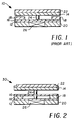
- Fig. 1 illustrates, in cross section view, a Prior Art example of a flat brushless D.C. motor;
- Fig. 2 illustrates, in cross section view, the preferred embodiment of a flat brushless D.C. motor;
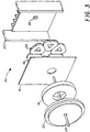
- Fig. 3 illustrates, in an exploded perspective view the preferred embodiment of the flat brushless D.C. motor of Fig. 2; and
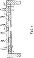
- Fig. 4 illustrates in a section view the mounting of the coil to the heat sink.
- Referring to the
prior art motor 10 illustrated in Fig. 1, it is common practice for brushless DC motors to be constructed with aflux return plate 12 that may be formed from silicon steel, to provide a flux return path for themotor magnet 14 and acircuit board 16 with the motors'coils 18 mounted to thecircuit board 16. It should be noted that theflux return plate 12 can be separate from, or integrated with amotor base 20. It should also be noted that themotor magnet 14 is capped by arotor 22 which is constructed with a magnetic material that effectively directs the flux stored inmotor magnet 14 through themotor coils 18. The correct application of current throughmotor coils 18 will cause a rotation of the motor on abearing 26 through ashaft 24 which is rigidly attached to therotor 22. This prior art arrangement suffers from the creation of excess heat especially on motors that are extremely small, but are required to generate large amounts of torque. The reason that the excess heat is formed is that thecoils 18 do not have an effective heat sink path. - The improved
motor 30 has itsmotor coils 18 andcircuit board 16 inverted so that the motor coils are in contact withflux return plate 12. This arrangement increases the heat transfer from thecoils 18 to theflux return plate 12 which is a much more efficient heat sink than air. Themotor coils 18 may be fixedly attached to theflux return plate 12 with a thermal paste or like material to further increase thermal transfer. Since the circuit board material is magnetically permeable, motor performance is largely unaffected except for a slight increase in the flux gap due to the thickness of the circuit board, and a reversal of motor commutation. - Referring to Figs.3 and 4, the
motor 30 is shown comprised of themotor coils 18 being positioned for assembly onto afinned heat sink 20'. Theheat sink 20', serves as themotor base 20 and also supports thebearing 26. Athermal paste 28 is applied betweencoil 18 and thefinned heat sink 20' to significantly enhance the transfer of heat from themotor coils 18 to thefinned heat sink 20'. This configuration, through the enhanced transfer of heat, prevents the increase in resistance of the motor coils due to heating and negates the requirement of increasing the drive current in response to increased coil resistance thus stabilizing motor operation. - The invention has been described with reference to a preferred embodiment. However, it will be appreciated that variations and modifications can be effected by a person of ordinary skill in the art without departing from the scope of the invention.
-
- 10
- Prior Art Motor
- 12
- Flux Return Plate
- 14
- Motor Magnet
- 16
- Circuit Board
- 18
- Motor Coils
- 20
- Motor Base
- 20'
- Finned Heat Sink
- 22
- Rotor
- 24
- Shaft
- 26
- Bearing
- 28
- Thermal Paste
- 30
- Improved Motor
Claims (10)
- A flat brushless motor of small size comprising:a thermally conductive base member;a plurality of motor coils fixedly attached to said base member; anda rotor assembly mounted proximately to said plurality of motor coils said motor assembly having a multiple pole permanent magnet incorporated therein.
- The flat brushless motor according to Claim 1 and further comprising:
a thermally conductive deformable layer positioned between said plurality of motor coils and said base member to facilitate the transfer of heat from said plurality of motor coils assembly to said base member. - The motor according to Claim 2 wherein said thermally conductive deformable layer is an electrically insulating thermally conductive grease.
- The motor according to Claim 2 wherein said thermally conductive deformable layer is an electrically insulating thermally conductive plastic.
- The motor according to Claim 1 wherein said thermally conductive base member is formed with a plurality of heat transmitting fins to facilitate the removal of heat from said plurality of motor coils.
- A motor of small size comprising:a heat sinking motor body member;a plurality of motor coils fixedly attached to said body member;a rotor assembly mounted proximately to said plurality of motor coils; andmeans for applying current to said plurality of motor coils so as to rotate said rotor assembly.
- The motor according to Claim 6 and further comprising:
a thermally conductive deformable layer positioned between said plurality of motor coils and said body member to facilitate the transfer of heat from said plurality of motor coils to said body member. - The motor according to Claim 7 wherein said thermally conductive deformable layer is an electrically insulating thermally conductive grease.
- The motor according to Claim 7 wherein said thermally conductive deformable layer is an electrically insulating thermally conductive plastic.
- The motor according to Claim 6 wherein said heat sinking motor body member is formed with a plurality of heat transmitting fins to facilitate the removal of heat from said plurality of motor coils.
Applications Claiming Priority (2)
| Application Number | Priority Date | Filing Date | Title |
|---|---|---|---|
| US451869 | 1995-05-26 | ||
| US08/451,869 US5686769A (en) | 1995-05-26 | 1995-05-26 | Method of coil mounting for maximum heat transfer in brushless DC motors |
Publications (2)
| Publication Number | Publication Date |
|---|---|
| EP0744811A2 true EP0744811A2 (en) | 1996-11-27 |
| EP0744811A3 EP0744811A3 (en) | 1997-09-03 |
Family
ID=23794041
Family Applications (1)
| Application Number | Title | Priority Date | Filing Date |
|---|---|---|---|
| EP96201400A Withdrawn EP0744811A3 (en) | 1995-05-26 | 1996-05-17 | Method of coil mounting for maximum heat transfer in DC brushless motors |
Country Status (3)
| Country | Link |
|---|---|
| US (1) | US5686769A (en) |
| EP (1) | EP0744811A3 (en) |
| JP (1) | JPH0947001A (en) |
Families Citing this family (4)
| Publication number | Priority date | Publication date | Assignee | Title |
|---|---|---|---|---|
| US6034465A (en) * | 1997-08-06 | 2000-03-07 | Shurfle Pump Manufacturing Co. | Pump driven by brushless motor |
| US5959384A (en) * | 1998-03-13 | 1999-09-28 | Mfm Technology, Inc. | Brushless motor housing assembly |
| US20080030088A1 (en) * | 2006-07-18 | 2008-02-07 | Daniel Gizaw | Compact integrated brushless permanent-magnet motor & drive |
| JP5511982B2 (en) * | 2010-01-11 | 2014-06-04 | シーメンス アクチエンゲゼルシヤフト | Direct drive wind turbine with cooling system and method for controlling a direct drive wind turbine |
Family Cites Families (25)
| Publication number | Priority date | Publication date | Assignee | Title |
|---|---|---|---|---|
| LU68101A1 (en) * | 1973-07-26 | 1973-11-22 | ||
| JPS577044B2 (en) * | 1974-02-14 | 1982-02-08 | ||
| US4008409A (en) * | 1975-04-09 | 1977-02-15 | General Electric Company | Dynamoelectric machine core and coil assembly |
| JPS5920267B2 (en) * | 1975-10-22 | 1984-05-11 | 株式会社日立製作所 | Electric motor with frequency generator |
| GB1565537A (en) * | 1975-10-23 | 1980-04-23 | Hitachi Ltd | Electric motor |
| CH612736A5 (en) * | 1976-04-27 | 1979-08-15 | Papst Motoren Kg | |
| JPS5445712A (en) * | 1977-09-19 | 1979-04-11 | Hitachi Ltd | Motor |
| JPS5526030A (en) * | 1978-08-14 | 1980-02-25 | Hitachi Ltd | Flat armature coil |
| JPS5947960A (en) * | 1982-09-10 | 1984-03-17 | Matsushita Electric Ind Co Ltd | Flat brushless motor |
| JPS6028750A (en) * | 1983-07-26 | 1985-02-13 | Mitsubishi Electric Corp | Stator coil cooling structure |
| DE3526166C2 (en) * | 1984-07-23 | 1996-05-02 | Asahi Chemical Ind | Brushless electric motor and method of manufacturing a coil unit therefor |
| JPS6146157A (en) * | 1984-08-07 | 1986-03-06 | Brother Ind Ltd | Brushless DC motor |
| JPS6146159A (en) * | 1984-08-09 | 1986-03-06 | Brother Ind Ltd | Brushless DC motor |
| JPH0526936Y2 (en) * | 1985-04-03 | 1993-07-08 | ||
| JPS6229770U (en) * | 1985-08-02 | 1987-02-23 | ||
| US4763037A (en) * | 1986-02-15 | 1988-08-09 | Aisin Seiki Kabushiki Kaisha | Flat motor having a stationary magnet |
| CH671855A5 (en) * | 1986-10-25 | 1989-09-29 | Papst Motoren Gmbh & Co Kg | |
| US4858073A (en) * | 1986-12-10 | 1989-08-15 | Akzo America Inc. | Metal substrated printed circuit |
| US4733115A (en) * | 1986-12-16 | 1988-03-22 | Eastman Kodak Company | Electric motor |
| JP2869064B2 (en) * | 1987-03-11 | 1999-03-10 | ソニー株式会社 | Disk drive |
| CH668160GA3 (en) * | 1987-04-22 | 1988-12-15 | ||
| JPS63299757A (en) * | 1987-05-28 | 1988-12-07 | Shicoh Eng Co Ltd | Disk type spindle brushless motor |
| US5124863A (en) * | 1989-06-27 | 1992-06-23 | Canon Denshi Kabushiki Kaisha | Disk drive device having reduced thickness |
| US5003429A (en) * | 1990-07-09 | 1991-03-26 | International Business Machines Corporation | Electronic assembly with enhanced heat sinking |
| JP2642548B2 (en) * | 1991-09-26 | 1997-08-20 | 株式会社東芝 | Semiconductor device and manufacturing method thereof |
-
1995
- 1995-05-26 US US08/451,869 patent/US5686769A/en not_active Expired - Fee Related
-
1996
- 1996-05-16 JP JP8121937A patent/JPH0947001A/en active Pending
- 1996-05-17 EP EP96201400A patent/EP0744811A3/en not_active Withdrawn
Also Published As
| Publication number | Publication date |
|---|---|
| US5686769A (en) | 1997-11-11 |
| JPH0947001A (en) | 1997-02-14 |
| EP0744811A3 (en) | 1997-09-03 |
Similar Documents
| Publication | Publication Date | Title |
|---|---|---|
| CN1075272C (en) | Electronically commutated reluctance motor | |
| JP3346039B2 (en) | Inverter integrated motor | |
| EP0376530A2 (en) | Integrated electronically commutated motor and control circuit assembly | |
| CN215120465U (en) | Electric pump | |
| KR20060049698A (en) | motor | |
| US4704566A (en) | Self-starting disk-type brushless motor with screw projection for generating cogging | |
| US5686769A (en) | Method of coil mounting for maximum heat transfer in brushless DC motors | |
| US4950932A (en) | Axial flow fan integral with electronically commutated motor | |
| US20200100393A1 (en) | Motor, printed circuit board, and engine cooling fan module including the motor | |
| US11121606B2 (en) | Motor, circuit board, and engine cooling module including the motor | |
| JPH08275432A (en) | Motor and manufacturing method thereof | |
| JPH10174406A (en) | Brushless fan motor | |
| JP3579571B2 (en) | Axial air fan motor | |
| GB2378047A (en) | Pole plate structure for a motor stator | |
| JPH08308180A (en) | Heat sink device | |
| JP3509288B2 (en) | Brushless DC motor | |
| JPH06327208A (en) | DC brushless motor stator | |
| JPH04168954A (en) | Stator of commutatorless motor | |
| JP2000320496A (en) | Small fan | |
| JP3509287B2 (en) | Brushless DC motor | |
| JP7725916B2 (en) | electric motor | |
| KR102760853B1 (en) | BLDC motor with a structure that prevent coil disconnection | |
| JPH0746811A (en) | Brushless motor fan | |
| TWI439012B (en) | Motor magnetic pole assembly and motor manufacturing method using the same | |
| US20030020356A1 (en) | Pole plate structure for a motor stator |
Legal Events
| Date | Code | Title | Description |
|---|---|---|---|
| PUAI | Public reference made under article 153(3) epc to a published international application that has entered the european phase |
Free format text: ORIGINAL CODE: 0009012 |
|
| AK | Designated contracting states |
Kind code of ref document: A2 Designated state(s): DE FR GB |
|
| PUAL | Search report despatched |
Free format text: ORIGINAL CODE: 0009013 |
|
| AK | Designated contracting states |
Kind code of ref document: A3 Designated state(s): DE FR GB |
|
| STAA | Information on the status of an ep patent application or granted ep patent |
Free format text: STATUS: THE APPLICATION IS DEEMED TO BE WITHDRAWN |
|
| 18D | Application deemed to be withdrawn |
Effective date: 19980304 |