EP0744252A1 - Seal device for rotary portion, and industrial robot provided at rotary portion thereof with seal device - Google Patents
Seal device for rotary portion, and industrial robot provided at rotary portion thereof with seal device Download PDFInfo
- Publication number
- EP0744252A1 EP0744252A1 EP95939379A EP95939379A EP0744252A1 EP 0744252 A1 EP0744252 A1 EP 0744252A1 EP 95939379 A EP95939379 A EP 95939379A EP 95939379 A EP95939379 A EP 95939379A EP 0744252 A1 EP0744252 A1 EP 0744252A1
- Authority
- EP
- European Patent Office
- Prior art keywords
- frame
- seal ring
- cylindrical
- section
- cover
- Prior art date
- Legal status (The legal status is an assumption and is not a legal conclusion. Google has not performed a legal analysis and makes no representation as to the accuracy of the status listed.)
- Withdrawn
Links
Images
Classifications
-
- B—PERFORMING OPERATIONS; TRANSPORTING
- B25—HAND TOOLS; PORTABLE POWER-DRIVEN TOOLS; MANIPULATORS
- B25J—MANIPULATORS; CHAMBERS PROVIDED WITH MANIPULATION DEVICES
- B25J19/00—Accessories fitted to manipulators, e.g. for monitoring, for viewing; Safety devices combined with or specially adapted for use in connection with manipulators
- B25J19/0075—Means for protecting the manipulator from its environment or vice versa
Definitions
- the present invention relates to seal devices for rotatable parts or components having a seal member disposed between a stationary section and its associated rotary section, and also to industrial robots with such seal devices at rotary sections thereof.
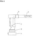
- Fig. 2 shows one typical industrial robot having seal devices at rotary sections thereof, wherein the reference character "A” designates a fixed base, “B” denotes a swivel base movably mounted on the upper section of the fixed base, “C” indicates a first arm rotatably attached to the swivel base, “D” is a second arm also rotatably coupled to a free end of the first arm, and “E” indicates a wrist rotatably coupled to a free end of the second arm. See Fig. 3, which shows one seal device that may be arranged at any one of the arms and wrist.
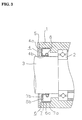
- the numeral 1 designates a frame that serves as a stationary section for constituting one of the arms and wrist
- 2 indicates a bearing as attached on the inner circumferential surface of the frame 1, said bearing supporting a shaft 3 acting as a drive shaft for the wrist, for example, while allowing shaft 3 to remain rotatable
- Numeral 4 denotes an annular seal ring which has a cylindrical section 4a and a flange section 4b and which is made of a chosen material with high wear resistance and/or solvent barrier characteristics
- 5 is a cover for protection of the interior of said frame 1, said cover being attached to the end of frame 1.
- Numerals 6, 7 designate metal rings consisting of tubular sections 6a, 7a and bottom sections 6b, 7b having shaft holes centrally defined therein.
- the flange section 4b of seal ring 4 is inserted and held by caulking between bottom sections 6b, 7b, while tubular sections 6a, 7a are inserted by compression into the gap between said bearing and cover so that they are compressively contacted with the inner circumferential surface of frame 1.
- Numeral 8 indicates an annular spring, which is attached to the outer peripheral surface of cylindrical section 4a of seal ring 4, causing the inner circumferential surface of tubular section 4b to be pressed toward shaft 3.
- the present invention provides a seal device for rotary components comprising a cylindrical frame, a shaft rotatably supported by a bearing on the inner circumferential surface of said frame, a ring-shaped cover attached to one of the longitudinally opposed edge portions of said frame, and a cylindrical seal ring disposed between said bearing and said cover and having at a cylindrical section thereof a flange section made of a chosen material with high wear resistance, wherein an annular spring is provided on the outer periphery of the cylindrical section of said seal ring for pressing the inner circumferential surface of said cylindrical section toward said shaft, while allowing the flange section to be held between the edge of said frame and said cover causing said seal ring to be fixed to said frame.
- the present invention also provides an industrial robot with a seal device at rotatable parts or components for actuation of one arm and a wrist, wherein said seal device comprises a cylindrical frame, a shaft rotatably supported by a bearing on the inner circumferential surface of said frame, a ring-shaped cover attached to one of the longitudinally opposed edge portions of said frame, and a cylindrical seal ring disposed between said bearing and said cover and having, at a cylindrical section thereof, a flange section made of a chosen material having high wear resistance, and wherein an annular spring is arranged on the outer periphery of the cylindrical section of said seal ring for pressing the inner circumferential surface of said cylindrical section toward said shaft, while allowing the flange section to be held between the edge of said frame and said cover causing said seal ring to be fixed to said frame.
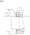
- Fig. 1 is a diagram showing a side cross-sectional view of a seal device in accordance with one preferred embodiment of the present invention.
- Fig. 2 is a side view of an industrial robot.
- Fig. 3 illustrates a side cross-section of one prior art seal device.
- Fig. 1 is a diagram showing a side cross-section of a seal device embodying the invention.
- the numeral 1 designates a frame which acts as a stationary section constituting one arm and wrist of an industrial robot
- numeral 2 indicates a bearing that is attached on the inner circumferential surface of frame 1 to rotatably support a shaft 3 serving as a drive shaft for the wrist or the like.
- Numeral 4 denotes a cylindrical seal ring which has a cylindrical section 4a and a flange section 4b made of a chosen material with high wear resistance and/or solvent barrier characteristic
- 5 is a cover for protection of the interior of frame 1, said cover being attached to the end of frame 1.
- Seal ring 4 is arranged so that flange section 4b is interposed between a longitudinal end surface of said frame 1 and cover 5, while an annular spring 8 is put on the outer peripheral surface of cylindrical section 4a so that spring 8 presses the inner circumferential surface of cylindrical section 4a toward said shaft 3.
- seal device in accordance with the present invention may be applied not only to industrial robots but also to other equipment, including machine tools, electric motors and others.
- the present invention is adaptable for use in the field of industrial robots to prevent contaminants such as dust, water, coating/painting solvents or the like from entering rotary sections thereof.
Landscapes
- Engineering & Computer Science (AREA)
- Robotics (AREA)
- Mechanical Engineering (AREA)
- Manipulator (AREA)
- Sealing Devices (AREA)
- Sealing Of Bearings (AREA)
Abstract
An annular spring (8) is fitted onto an outer peripheral surface of a cylindrical portion (4a) of a seal ring (4) in a manner to push an inner peripheral surface of the cylindrical portion (4a) toward a shaft (3), and a flange portion of the seal ring (4) is held between an axial end face of a frame (1) and a cover (5) to fix the seal ring (4) to the frame (1). The seal ring can be fixed and removed in a simple, positive and inexpensive manner, for example, by a frame and a cover of an industrial robot without the use of separate parts.
Description
- The present invention relates to seal devices for rotatable parts or components having a seal member disposed between a stationary section and its associated rotary section, and also to industrial robots with such seal devices at rotary sections thereof.
- Fig. 2 shows one typical industrial robot having seal devices at rotary sections thereof, wherein the reference character "A" designates a fixed base, "B" denotes a swivel base movably mounted on the upper section of the fixed base, "C" indicates a first arm rotatably attached to the swivel base, "D" is a second arm also rotatably coupled to a free end of the first arm, and "E" indicates a wrist rotatably coupled to a free end of the second arm. See Fig. 3, which shows one seal device that may be arranged at any one of the arms and wrist. In this drawing, the
numeral 1 designates a frame that serves as a stationary section for constituting one of the arms and wrist, whereas 2 indicates a bearing as attached on the inner circumferential surface of theframe 1, said bearing supporting ashaft 3 acting as a drive shaft for the wrist, for example, while allowingshaft 3 to remain rotatable. Numeral 4 denotes an annular seal ring which has acylindrical section 4a and aflange section 4b and which is made of a chosen material with high wear resistance and/or solvent barrier characteristics; 5 is a cover for protection of the interior of saidframe 1, said cover being attached to the end offrame 1.Numerals tubular sections bottom sections flange section 4b ofseal ring 4 is inserted and held by caulking betweenbottom sections tubular sections frame 1.Numeral 8 indicates an annular spring, which is attached to the outer peripheral surface ofcylindrical section 4a ofseal ring 4, causing the inner circumferential surface oftubular section 4b to be pressed towardshaft 3. With such an arrangement, even when contaminants including dust, water, solvents such as coating/painting materials or the like appear to be ready to enter or "invade" the interior of the robot through gaps as possibly defined betweenframe 1 andshaft 3, such contaminants will no longer be able to enter the inside of the robot becauseseal ring 4 will be in contact with the outer peripheral surface ofshaft 3 in any event. - The prior art suffers from the following problems:
- (1)
Seal ring 4 remains costly, as it is caulked by and held betweenmetal rings metal rings frame 1 be increased accordingly, making fabrication more difficult. - (2) Due to the structure in which
tubular sections 5a, 6a ofmetal rings frame 1, greater accuracy in size determination is required, which may in turn lead to a risk of tolerance variations in the outer diameter to adversely affect the assembly thereof. Furthermore, such compressive insertions ofmetal rings - (3) The joint planes of
metal rings - Accordingly, it is an object of the present invention to provide a sealing method capable of attaining enhanced sealing performance while allowing a sealing member to be less costly, smaller, and easier to disassemble.
- To attain the foregoing object, the present invention provides a seal device for rotary components comprising a cylindrical frame, a shaft rotatably supported by a bearing on the inner circumferential surface of said frame, a ring-shaped cover attached to one of the longitudinally opposed edge portions of said frame, and a cylindrical seal ring disposed between said bearing and said cover and having at a cylindrical section thereof a flange section made of a chosen material with high wear resistance, wherein an annular spring is provided on the outer periphery of the cylindrical section of said seal ring for pressing the inner circumferential surface of said cylindrical section toward said shaft, while allowing the flange section to be held between the edge of said frame and said cover causing said seal ring to be fixed to said frame.
- The present invention also provides an industrial robot with a seal device at rotatable parts or components for actuation of one arm and a wrist, wherein said seal device comprises a cylindrical frame, a shaft rotatably supported by a bearing on the inner circumferential surface of said frame, a ring-shaped cover attached to one of the longitudinally opposed edge portions of said frame, and a cylindrical seal ring disposed between said bearing and said cover and having, at a cylindrical section thereof, a flange section made of a chosen material having high wear resistance, and wherein an annular spring is arranged on the outer periphery of the cylindrical section of said seal ring for pressing the inner circumferential surface of said cylindrical section toward said shaft, while allowing the flange section to be held between the edge of said frame and said cover causing said seal ring to be fixed to said frame.
- Significant advantages of the present invention as derived from the aforesaid aspects thereof are as follows:
- (1) It is possible, without the use of any extra parts or components, to assemble and disassemble the seal ring easily and reliably at lower costs by use of a combination of frame and cover of industrial robots, for example. Also, since the frame no longer requires cutting operations for fabrication of its inner circumferential surface, the manufacture thereof remains simpler.
- (2) Attachment of the seal ring requires little or no limitations in determination of radial size, enabling members and parts to be free from any strict requirements regarding high dimensional accuracy.
- (3) No direct contact of sealed sections with exposed metal surfaces is present, thus enhancing the sealing performance.
- Fig. 1 is a diagram showing a side cross-sectional view of a seal device in accordance with one preferred embodiment of the present invention. Fig. 2 is a side view of an industrial robot. Fig. 3 illustrates a side cross-section of one prior art seal device.
- One preferred embodiment of the present invention will now be described with reference to the accompanying drawing. Fig. 1 is a diagram showing a side cross-section of a seal device embodying the invention. In Fig.1, the
numeral 1 designates a frame which acts as a stationary section constituting one arm and wrist of an industrial robot;numeral 2 indicates a bearing that is attached on the inner circumferential surface offrame 1 to rotatably support ashaft 3 serving as a drive shaft for the wrist or the like. Numeral 4 denotes a cylindrical seal ring which has acylindrical section 4a and aflange section 4b made of a chosen material with high wear resistance and/or solvent barrier characteristic; 5 is a cover for protection of the interior offrame 1, said cover being attached to the end offrame 1.Seal ring 4 is arranged so thatflange section 4b is interposed between a longitudinal end surface of saidframe 1 andcover 5, while anannular spring 8 is put on the outer peripheral surface ofcylindrical section 4a so thatspring 8 presses the inner circumferential surface ofcylindrical section 4a toward saidshaft 3. - In the illustrative arrangement, even when contaminants such as dust, water, solvent approach the interior of the robot through gaps as possibly defined between the
frame 1 andshaft 3, such contaminants can no longer enter the inside of the robot becauseseal ring 4 is always in contact with the outer peripheral surface ofshaft 3. - It should be noted that the seal device in accordance with the present invention may be applied not only to industrial robots but also to other equipment, including machine tools, electric motors and others.
- The present invention is adaptable for use in the field of industrial robots to prevent contaminants such as dust, water, coating/painting solvents or the like from entering rotary sections thereof.
Claims (2)
- A seal device for rotary components comprising a cylindrical frame, a shaft rotatably supported by a bearing on an inner circumferential surface of said frame, a ring-shaped cover attached to one of the longitudinally opposed edges of said frame, and a cylindrical seal ring disposed between said bearing and said cover and having at a cylindrical section thereof a flange section made of a chosen material with high wear resistance,
characterized in that an annular spring is on an outer periphery of the cylindrical section of said seal ring for pressing the inner circumferential surface of said cylindrical section toward said shaft while allowing the flange section to be held between the edge of said frame and said cover causing said seal ring to be fixed to said frame. - An industrial robot with a seal device at rotatable components for actuation of one of an arm and a wrist, wherein said seal device comprises a cylindrical frame, a shaft rotatably supported by a bearing on an inner circumferential surface of said frame, a ring-shaped cover attached to one of the longitudinally opposed edges of said frame, and a cylindrical seal ring disposed between said bearing and said cover and having at a cylinder section thereof a flange section made of a chosen material with high wear resistance, and wherein an annular spring is on an outer periphery of the cylinder section of said seal ring for pressing the inner circumferential surface of said cylindrical section toward said shaft while allowing the flange section to be held between the edge of said frame and said cover causing said seal ring to be fixed to said frame.
Applications Claiming Priority (3)
| Application Number | Priority Date | Filing Date | Title |
|---|---|---|---|
| JP331298/94 | 1994-12-07 | ||
| JP33129894A JP3656916B2 (en) | 1994-12-07 | 1994-12-07 | Rotating part sealing device, and industrial robot equipped with rotating part sealing device |
| PCT/JP1995/002493 WO1996017713A1 (en) | 1994-12-07 | 1995-12-06 | Seal device for rotary portion, and industrial robot provided at rotary portion thereof with seal device |
Publications (2)
| Publication Number | Publication Date |
|---|---|
| EP0744252A1 true EP0744252A1 (en) | 1996-11-27 |
| EP0744252A4 EP0744252A4 (en) | 1998-03-18 |
Family
ID=18242127
Family Applications (1)
| Application Number | Title | Priority Date | Filing Date |
|---|---|---|---|
| EP95939379A Withdrawn EP0744252A4 (en) | 1994-12-07 | 1995-12-06 | Seal device for rotary portion, and industrial robot provided at rotary portion thereof with seal device |
Country Status (4)
| Country | Link |
|---|---|
| EP (1) | EP0744252A4 (en) |
| JP (1) | JP3656916B2 (en) |
| CN (1) | CN1140427A (en) |
| WO (1) | WO1996017713A1 (en) |
Cited By (3)
| Publication number | Priority date | Publication date | Assignee | Title |
|---|---|---|---|---|
| CN107206596A (en) * | 2014-12-03 | 2017-09-26 | Abb瑞士股份有限公司 | protection device, end effector and robot |
| WO2020192862A1 (en) * | 2019-03-22 | 2020-10-01 | Abb Schweiz Ag | A seal arrangement for a robot joint |
| US11285622B2 (en) * | 2019-01-31 | 2022-03-29 | Fanuc Corporation | Wrist structure of robot, and robot |
Families Citing this family (7)
| Publication number | Priority date | Publication date | Assignee | Title |
|---|---|---|---|---|
| JP3679871B2 (en) * | 1996-09-04 | 2005-08-03 | 株式会社荏原製作所 | Polishing apparatus and transfer robot |
| JPH1076493A (en) * | 1996-09-04 | 1998-03-24 | Ebara Corp | Waterproofing mechanism for work conveying robot |
| DE10348841B4 (en) * | 2003-10-21 | 2005-12-15 | Kuka Roboter Gmbh | Device with relatively rotatable parts and a sealing arrangement |
| JP2008055560A (en) * | 2006-08-31 | 2008-03-13 | Fanuc Ltd | Sealing device for joint section of robot and articulated robot |
| JP5580378B2 (en) * | 2012-08-31 | 2014-08-27 | ファナック株式会社 | Articulated robot having a cover attached to an end effector mounting portion |
| CN103072144A (en) * | 2012-12-28 | 2013-05-01 | 袁祖六 | Light manipulator rotating joint |
| CN115003937A (en) | 2020-05-03 | 2022-09-02 | Abb瑞士股份有限公司 | Sealing assembly and robot |
Citations (5)
| Publication number | Priority date | Publication date | Assignee | Title |
|---|---|---|---|---|
| GB562922A (en) * | 1943-01-18 | 1944-07-21 | Horace Francis Petch | Improvements in or relating to oil seals |
| US2621987A (en) * | 1946-02-23 | 1952-12-16 | Augereau Gaston Georges Eugene | Oil-lubricated bearing block |
| US3902726A (en) * | 1974-03-15 | 1975-09-02 | Chuetsu Waukesha Co Ltd | Stern tube sealing device |
| DE3627745A1 (en) * | 1985-08-20 | 1987-03-05 | Tokico Ltd | INDUSTRIAL PLAYER ROBOT |
| DE3616780A1 (en) * | 1986-05-17 | 1987-11-19 | Voith Turbo Kg | Seal arrangement |
Family Cites Families (2)
| Publication number | Priority date | Publication date | Assignee | Title |
|---|---|---|---|---|
| JPS49139451U (en) * | 1973-03-31 | 1974-11-30 | ||
| JPS6423388U (en) * | 1987-07-30 | 1989-02-07 |
-
1994
- 1994-12-07 JP JP33129894A patent/JP3656916B2/en not_active Expired - Lifetime
-
1995
- 1995-12-06 WO PCT/JP1995/002493 patent/WO1996017713A1/en not_active Application Discontinuation
- 1995-12-06 CN CN 95191523 patent/CN1140427A/en active Pending
- 1995-12-06 EP EP95939379A patent/EP0744252A4/en not_active Withdrawn
Patent Citations (5)
| Publication number | Priority date | Publication date | Assignee | Title |
|---|---|---|---|---|
| GB562922A (en) * | 1943-01-18 | 1944-07-21 | Horace Francis Petch | Improvements in or relating to oil seals |
| US2621987A (en) * | 1946-02-23 | 1952-12-16 | Augereau Gaston Georges Eugene | Oil-lubricated bearing block |
| US3902726A (en) * | 1974-03-15 | 1975-09-02 | Chuetsu Waukesha Co Ltd | Stern tube sealing device |
| DE3627745A1 (en) * | 1985-08-20 | 1987-03-05 | Tokico Ltd | INDUSTRIAL PLAYER ROBOT |
| DE3616780A1 (en) * | 1986-05-17 | 1987-11-19 | Voith Turbo Kg | Seal arrangement |
Non-Patent Citations (1)
| Title |
|---|
| See also references of WO9617713A1 * |
Cited By (6)
| Publication number | Priority date | Publication date | Assignee | Title |
|---|---|---|---|---|
| CN107206596A (en) * | 2014-12-03 | 2017-09-26 | Abb瑞士股份有限公司 | protection device, end effector and robot |
| EP3227064A4 (en) * | 2014-12-03 | 2018-07-18 | ABB Schweiz AG | Protection apparatus, end effector and robot |
| US10603801B2 (en) | 2014-12-03 | 2020-03-31 | Abb Schweiz Ag | Protection apparatus, end effector and robot |
| CN107206596B (en) * | 2014-12-03 | 2020-11-17 | Abb瑞士股份有限公司 | Protection device, end effector and robot |
| US11285622B2 (en) * | 2019-01-31 | 2022-03-29 | Fanuc Corporation | Wrist structure of robot, and robot |
| WO2020192862A1 (en) * | 2019-03-22 | 2020-10-01 | Abb Schweiz Ag | A seal arrangement for a robot joint |
Also Published As
| Publication number | Publication date |
|---|---|
| EP0744252A4 (en) | 1998-03-18 |
| WO1996017713A1 (en) | 1996-06-13 |
| JP3656916B2 (en) | 2005-06-08 |
| JPH08155882A (en) | 1996-06-18 |
| CN1140427A (en) | 1997-01-15 |
Similar Documents
| Publication | Publication Date | Title |
|---|---|---|
| EP0744252A1 (en) | Seal device for rotary portion, and industrial robot provided at rotary portion thereof with seal device | |
| US4981303A (en) | Sealing device | |
| US5269536A (en) | Sealing device | |
| JPH0579861B2 (en) | ||
| US3971565A (en) | Seal assembly for pillow block housing | |
| USRE35309E (en) | Sealing device | |
| JP4865571B2 (en) | Shaft seal device | |
| EP1134465A3 (en) | Lip type seal | |
| JPH0227526B2 (en) | ||
| US6454269B2 (en) | Mechanical device with sealing means and method for mounting the sealing means | |
| JP2003052145A (en) | Oil-sealing structure for motor | |
| CN113942033A (en) | Joint casing, joint assembly and robot | |
| JPH0595173U (en) | Motor with built-in electromagnetic brake | |
| CN221003743U (en) | Sealing member and sealing structure | |
| CN111902662B (en) | Sealing device | |
| JPH11108198A (en) | Sealing device | |
| JPS582128Y2 (en) | Shaft sealing device for fully enclosed outer cover in rotating electrical machines | |
| EP0869289A3 (en) | Mounting of a shaft within a housing with a preloaded bearing | |
| JPH0741972Y2 (en) | Sealing device | |
| JPH073089Y2 (en) | Sealing device | |
| JPH0640451Y2 (en) | Explosion-proof motor with brake | |
| WO2002093030A3 (en) | Resiliently mounted bearing | |
| JPH064468U (en) | Floating ring seal load ring | |
| JP2000046188A (en) | Sealing device | |
| JPS5913180Y2 (en) | Steering gear dustproof and waterproof device |
Legal Events
| Date | Code | Title | Description |
|---|---|---|---|
| PUAI | Public reference made under article 153(3) epc to a published international application that has entered the european phase |
Free format text: ORIGINAL CODE: 0009012 |
|
| AK | Designated contracting states |
Kind code of ref document: A1 Designated state(s): DE FR GB IT |
|
| 17P | Request for examination filed |
Effective date: 19961203 |
|
| A4 | Supplementary search report drawn up and despatched |
Effective date: 19980127 |
|
| AK | Designated contracting states |
Kind code of ref document: A4 Designated state(s): DE FR GB IT |
|
| 17Q | First examination report despatched |
Effective date: 19981117 |
|
| STAA | Information on the status of an ep patent application or granted ep patent |
Free format text: STATUS: THE APPLICATION IS DEEMED TO BE WITHDRAWN |
|
| 18D | Application deemed to be withdrawn |
Effective date: 19991221 |