EP0744240B1 - Tack gripper for a tack welding gun and process for connecting a strip-form workpiece to a component - Google Patents
Tack gripper for a tack welding gun and process for connecting a strip-form workpiece to a component Download PDFInfo
- Publication number
- EP0744240B1 EP0744240B1 EP96303426A EP96303426A EP0744240B1 EP 0744240 B1 EP0744240 B1 EP 0744240B1 EP 96303426 A EP96303426 A EP 96303426A EP 96303426 A EP96303426 A EP 96303426A EP 0744240 B1 EP0744240 B1 EP 0744240B1
- Authority
- EP
- European Patent Office
- Prior art keywords
- tack
- tack gripper
- arm
- gripper according
- arms
- Prior art date
- Legal status (The legal status is an assumption and is not a legal conclusion. Google has not performed a legal analysis and makes no representation as to the accuracy of the status listed.)
- Expired - Lifetime
Links
- 238000003466 welding Methods 0.000 title claims description 32
- 238000000034 method Methods 0.000 title claims description 18
- 238000001816 cooling Methods 0.000 claims description 16
- 239000002826 coolant Substances 0.000 claims description 12
- 238000005452 bending Methods 0.000 claims description 3
- 230000001681 protective effect Effects 0.000 claims description 3
- XLYOFNOQVPJJNP-UHFFFAOYSA-N water Substances O XLYOFNOQVPJJNP-UHFFFAOYSA-N 0.000 claims description 3
- 229910000906 Bronze Inorganic materials 0.000 claims description 2
- 239000010974 bronze Substances 0.000 claims description 2
- KUNSUQLRTQLHQQ-UHFFFAOYSA-N copper tin Chemical compound [Cu].[Sn] KUNSUQLRTQLHQQ-UHFFFAOYSA-N 0.000 claims description 2
- 238000004140 cleaning Methods 0.000 description 3
- 238000004519 manufacturing process Methods 0.000 description 3
- 238000011109 contamination Methods 0.000 description 2
- 239000000463 material Substances 0.000 description 2
- 230000035882 stress Effects 0.000 description 2
- 210000002105 tongue Anatomy 0.000 description 2
- 229910000639 Spring steel Inorganic materials 0.000 description 1
- 230000002411 adverse Effects 0.000 description 1
- 230000005540 biological transmission Effects 0.000 description 1
- 210000000746 body region Anatomy 0.000 description 1
- 238000010276 construction Methods 0.000 description 1
- 238000004049 embossing Methods 0.000 description 1
- 238000011089 mechanical engineering Methods 0.000 description 1
- 238000010422 painting Methods 0.000 description 1
- 239000007787 solid Substances 0.000 description 1
- 125000006850 spacer group Chemical group 0.000 description 1
- 238000003860 storage Methods 0.000 description 1
- 230000008646 thermal stress Effects 0.000 description 1
Images
Classifications
-
- B—PERFORMING OPERATIONS; TRANSPORTING
- B23—MACHINE TOOLS; METAL-WORKING NOT OTHERWISE PROVIDED FOR
- B23K—SOLDERING OR UNSOLDERING; WELDING; CLADDING OR PLATING BY SOLDERING OR WELDING; CUTTING BY APPLYING HEAT LOCALLY, e.g. FLAME CUTTING; WORKING BY LASER BEAM
- B23K11/00—Resistance welding; Severing by resistance heating
- B23K11/14—Projection welding
-
- B—PERFORMING OPERATIONS; TRANSPORTING
- B23—MACHINE TOOLS; METAL-WORKING NOT OTHERWISE PROVIDED FOR
- B23K—SOLDERING OR UNSOLDERING; WELDING; CLADDING OR PLATING BY SOLDERING OR WELDING; CUTTING BY APPLYING HEAT LOCALLY, e.g. FLAME CUTTING; WORKING BY LASER BEAM
- B23K37/00—Auxiliary devices or processes, not specially adapted for a procedure covered by only one of the other main groups of this subclass
- B23K37/04—Auxiliary devices or processes, not specially adapted for a procedure covered by only one of the other main groups of this subclass for holding or positioning work
- B23K37/0426—Fixtures for other work
Definitions
- the present invention relates to a tack gripper for a tack welding gun according to the preamble of claim 1 and to a process for connecting a preferably strip-shaped workpiece to a component.
- Welding has evolved in mechanical engineering to a production process with broad applications which is adopted in particular in the case of light construction. Welding also affords an excellent opportunity to reduce the assembly cost of components.
- welding is the main process for body assembly. Workpieces which serve as fastening and/or holding elements are welded on the vehicle body.
- tack grippers For the tack welding of workpieces, in particular strip-form workpieces, welding guns are provided with tack grippers one example of which is shown in US-A-4771160. These tack grippers are designed in the form of tongs. As a result, these tack grippers have a plurality of mechanically moving parts. Welding spatter which impairs the operability of the mechanically moving parts of the tack gripper can be formed during the welding process. In addition to such welding spatter, the mechanically moving parts are contaminated so the mechanically moving parts are subject to increased wear in the course of time. It may also happen that the holding force of the tack gripper no longer suffices as the tong-form tack gripper is inaccessible.
- the tack gripper is also to be almost self-cleaning in design.
- a further object is to provide a process by means of which a strip-form workpiece can be reliably and economically connected to a component.
- a further object of the invention is to design a workpiece in such a way that it can be gripped reliably and positioned exactly by a tack gripper.
- the present invention provides a tack gripper for a tack welding gun, which tack gripper is in the form of a U with two arms connected via, a base, characterised in that the arms are rigidly secured to the base and at least one free arm of the tack gripper is sufficiently resilient to provide the force and deformation of the arm which are necessary to grab a workpiece and maintain it between the arms.
- the tack gripper according to the invention has at least one resilient free arm instead of mechanically moving parts.
- a frictional joint is created between the tack gripper and a component which is clamped between the arms.
- the distance between the arms is dimensioned so that the arms are spread automatically during gripping of the workpiece.
- the surfaces of the arms rub against the surfaces of the workpiece so the surfaces of the arms, which also act as contact surfaces for the welding current to be introduced are cleaned.
- the cleaning process is repeated when the tack gripper is removed from the workpiece so two cleaning processes invariably take place during one welding process.
- Each arm is preferably detachably connected to the base.
- the arms can therefore easily be exchanged.
- a further advantage of this design is that the distance between the arms can be increased by spacer members arranged between the base and the arm.
- the tack gripper can therefore easily be adapted to workpieces of various thicknesses.
- At least one arm is designed with at least one hole in the region adjacent to its free end. If several holes are provided, they are aligned in a line extending transversely to the length of the arm.
- the design of the tack gripper has the advantage that a workpiece can be provided with catch knobs which engage at least partially in a hole in the arm. This allows, on the one hand, reliable transmission of the welding current and, on the other hand, exact positioning of the workpiece in the tack gripper.
- At least one arm of the tack gripper has, at its free end, a portion which is bent over itself, the portion being arranged between the arms. If holes are provided in the arms, they are formed in the bent over portion.
- the bent over portion has the advantage of simplifying the introduction of a workpiece into the space between the arms or the portions. The bent over portion also increases the spring action of the arms.
- the welding current is transmitted through the arms.
- the electric resistance of the arms should therefore be as low as possible.
- Bronze is a suitable material for forming the arms and/or the base.
- the spring strength or spring rating of the material of which the arms consist can sometimes be too low to produce an adequate holding force. It is therefore proposed that at least one arm be spreadable against an additional spring force.
- At least one spring element arranged on an arm is provided for this purpose.
- This spring element can be a spring subjected to bending stress, the spring element being fixed at one end in a region of the arm in which the arm at least partially overlaps the base.
- a spring element which is a leaf spring is preferred.
- the leaf spring can also consist of spring steel.
- the spring element is designed in such a way that it is curved in an arc toward the arm, at least at its free end.
- the welding current is preferably introduced into the workpiece via the base and the arms.
- the base is formed by a cuboid carrier having a connection to the welding head of the tack welding gun on one of its end faces.
- the arms and, optionally, the spring element or the spring elements are preferably screwed to the cuboid carrier.
- each arm In order to centre the arms on the carrier, each arm has a groove in which a respective base formed on the carrier engages.
- the centring of the arms is particularly important if each arm has, in a region adjacent to its free end, at least one hole which co-operates with catch knobs formed on the workpiece.
- the arms of the tack gripper are identical in design.
- the storage of spare arms is therefore also minimised.
- the leaf springs can be standard springs.
- the thermal stress on the tack gripper during the welding process can be considerable. If the tack gripper is used in a handling device, the time interval between two welding processes is sometimes too small to allow adequate cooling of the tack gripper. It is therefore proposed that the tack gripper be designed so as to allow the fastest possible discharge of heat, and therefore cooling, of the tack gripper. It is proposed for this purpose that the base and/or the arms be provided with at least one cooling fin. If the convective cooling of the tack gripper is not adequate or not fast enough, the base can be designed with at least one cooling duct which is connected to a coolant supply system, instead of or in addition to cooling fins. The base can have several cooling ducts for this purpose.
- the duct or ducts formed in the base be connected to the coolant supply system via a feed conduit and a discharge conduit.
- the coolants can be protective gas, water and/or air. It is particularly appropriate to use protective gas as coolant as it is required during the cooling process anyway.
- the tack gripper according to the invention for a tack welding gun is preferably used for workpieces comprising at least a pair of gripping surfaces grippable by a tack gripper, at least one of the gripping surfaces being designed with at least one catch knob engaging at least partially in a hole in an arm.
- the catch knobs are preferably formed by embossing.
- the height of the catch knobs is preferably between 0.3 and 0.5 mm. The height is adequate to ensure a secure hold in the holes. However, the knobs are not so markedly embossed that they are still visible after painting of the workpiece.
- a process for connecting a strip-form workpiece preferably a workpiece comprising catch knobs on the gripping surfaces
- a tack gripper of a tack welding gun grips and frictionally holds a portion of a metallic band.
- a separating device severs a strip of predetermined length from the band. The strip forms a workpiece.
- the workpiece held by the tack gripper is initially positioned on the component and then welded thereto. On termination of the welding process, the tack gripper is removed from the workpiece.
- the tack gripper can grip another portion of a metallic band. The procedure is repeated.
- the process is automated in this way.
- the tack gripper formed on the tack welding gun avoids the need for further feed arrangements.
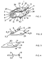
- FIG 1 shows an embodiment of a tack gripper 1 which is U-shaped in design.
- the tack gripper comprises a base 4 to which two arms 2, 3 are connected.
- the base 4 is formed by a cuboid carrier 13. Bores (not shown) through which screws 23 extend are formed in the carrier 13. The screws 23 are screwed to nuts 30.
- a receiving bore 24 is formed in the carrier 13 and serves to connect the tack gripper 1 to the welding head of a tack welding gun and to the welding current supply.
- the carrier 13 has cooling ducts 31 through which a coolant such as water can be conveyed. Connecting lines which connect a coolant supply system to the cooling ducts 31 are not shown.
- the carrier 13 and/or the arms 2, 3 can be provided with cooling fins in addition to or instead of the cooling ducts 31.
- the term cooling fins includes plane fins and rod-shaped fins. If plane fins are formed on the arms 2, 3, they preferably extend transversely to the length of the arms 2, 3 to prevent the resilience of the arms 2, 3 being eliminated by plane fins.
- Each arm 2, 3 is resilient in design.
- the arms 2, 3 are identical in design.
- Each arm 2, 3 has holes 5, 6, 7 in a region 12 adjacent to its free end.
- the holes 5, 6, 7 are aligned transversely to the length of the arm 2, 3.
- the arm 2, 3 has, at its free end, a portion 8 or 9 which is bent over itself.
- the portion 8 or 9 is arranged between the arms. As shown in Figure 2, the holes 5, 6 and 7 are formed in the bent over portion 8 or 9.
- the two arms 2, 3 can be spread against an additional spring force in each case.
- a spring element 10 or 11 is arranged on the arm 2 or 3. This spring element 10, 11 is a spring subjected to bending stress.
- the spring element 10, 11 is fixed at one end in a region of the arm 2, 3 by the screw connection 23.
- the spring element 10 or 11 has three resilient tongues 25, 26 and 27 which are formed at a distance from one another. Each spring tongue 25, 26 and 27 is curved in the form of an arc to the arm 2 or 3 in its front region.
- Each arm 2, 3 has a groove 14, 15 in which a respective projection 16 or 17 formed on the carrier 13 engages.
- the arm 2 or 3 has orifices 28, 29 through which a screw 23 penetrates.
- Corresponding apertures are formed on the respective spring element 10 or 11.
- FIG. 3 shows a workpiece 20.
- the workpiece 20 is a strip-form part.
- the workpiece 20 has a pair of gripping surfaces 21, 22 which can be gripped by a tack gripper 1.
- Catch knobs 18 are formed on the gripping surface 21.
- a catch knob 19 is formed on the gripping surface 22.
- the knobs 18, 19 lie on an imaginary straight connecting line.
- the design of the knobs 18, 19 creates three-point contact which provides a defined location for the workpiece 13 in the tack gripper.
- the catch knobs 18 or 19 are arranged in such a way that the catch knobs engage in the holes 5, 6, 7 of the arm 2 or 3.
Landscapes
- Engineering & Computer Science (AREA)
- Mechanical Engineering (AREA)
- Physics & Mathematics (AREA)
- Optics & Photonics (AREA)
- Resistance Welding (AREA)
- Arc Welding In General (AREA)
- Butt Welding And Welding Of Specific Article (AREA)
Applications Claiming Priority (2)
| Application Number | Priority Date | Filing Date | Title |
|---|---|---|---|
| DE19519443A DE19519443A1 (de) | 1995-05-26 | 1995-05-26 | Heftgreifer für eine Heftschweißpistole und Verfahren zum Verbinden eines streifenförmigen Werkstückes mit einem Bauteil |
| DE19519443 | 1995-05-26 |
Publications (2)
| Publication Number | Publication Date |
|---|---|
| EP0744240A1 EP0744240A1 (en) | 1996-11-27 |
| EP0744240B1 true EP0744240B1 (en) | 1999-08-18 |
Family
ID=7763000
Family Applications (1)
| Application Number | Title | Priority Date | Filing Date |
|---|---|---|---|
| EP96303426A Expired - Lifetime EP0744240B1 (en) | 1995-05-26 | 1996-05-15 | Tack gripper for a tack welding gun and process for connecting a strip-form workpiece to a component |
Country Status (4)
| Country | Link |
|---|---|
| US (2) | US5868303A (enExample) |
| EP (1) | EP0744240B1 (enExample) |
| JP (1) | JPH0999372A (enExample) |
| DE (2) | DE19519443A1 (enExample) |
Families Citing this family (4)
| Publication number | Priority date | Publication date | Assignee | Title |
|---|---|---|---|---|
| US6236018B1 (en) | 1998-05-26 | 2001-05-22 | Emhart Inc. | Part feeder system |
| DE10152685A1 (de) * | 2001-10-19 | 2003-05-08 | Thyssenkrupp Stahl Ag | Vorrichtung zur lokalen induktiven Wärmebehandlung eines geschweißten Werkstücks |
| CN103659105B (zh) * | 2013-11-15 | 2015-09-30 | 柳州市莱纳汽车部件有限公司 | 一种焊接工装夹具 |
| CN104439843B (zh) * | 2014-11-28 | 2016-06-15 | 上海气焊机厂有限公司 | 夹紧定位装置 |
Family Cites Families (8)
| Publication number | Priority date | Publication date | Assignee | Title |
|---|---|---|---|---|
| US1748346A (en) * | 1928-10-11 | 1930-02-25 | Hollup Corp | Electrode holder |
| US2376957A (en) * | 1943-08-11 | 1945-05-29 | William L Forker | Tool for aligning plates |
| LU58692A1 (enExample) * | 1968-07-11 | 1969-08-28 | ||
| US3729125A (en) * | 1969-09-06 | 1973-04-24 | Nippon Kokan Kk | Tack-welding method and installation |
| US3678241A (en) * | 1970-07-31 | 1972-07-18 | Continental Can Co | Inert atmosphere tack welder |
| JPS57115984A (en) * | 1981-01-13 | 1982-07-19 | Honda Motor Co Ltd | Method for tack welding of metallic member |
| DE3524342A1 (de) | 1985-07-08 | 1987-01-15 | Daimler Benz Ag | Punktschweisszange fuer maschinellen einsatz |
| US6025569A (en) | 1998-09-03 | 2000-02-15 | Senco Products, Inc. | Magazine and a stud advancing system for use with a manual stud welding tool |
-
1995
- 1995-05-26 DE DE19519443A patent/DE19519443A1/de not_active Withdrawn
-
1996
- 1996-05-15 DE DE69603785T patent/DE69603785T2/de not_active Expired - Fee Related
- 1996-05-15 EP EP96303426A patent/EP0744240B1/en not_active Expired - Lifetime
- 1996-05-23 US US08/651,461 patent/US5868303A/en not_active Ceased
- 1996-05-27 JP JP8170772A patent/JPH0999372A/ja active Pending
-
2000
- 2000-10-18 US US09/691,859 patent/USRE37735E1/en not_active Expired - Lifetime
Also Published As
| Publication number | Publication date |
|---|---|
| JPH0999372A (ja) | 1997-04-15 |
| DE69603785T2 (de) | 2000-03-02 |
| USRE37735E1 (en) | 2002-06-11 |
| EP0744240A1 (en) | 1996-11-27 |
| US5868303A (en) | 1999-02-09 |
| DE19519443A1 (de) | 1996-11-28 |
| DE69603785D1 (de) | 1999-09-23 |
Similar Documents
| Publication | Publication Date | Title |
|---|---|---|
| EP0190359A1 (en) | Nozzle for gas-shielded arc welding | |
| US6852950B2 (en) | Welding gun having a removable nozzle end portion and method for operating same | |
| US8426774B2 (en) | Welding gun | |
| US20160193686A1 (en) | Welding gun having non-threading contact tip | |
| EP0696492B1 (en) | Wire feeder torch | |
| EP0744240B1 (en) | Tack gripper for a tack welding gun and process for connecting a strip-form workpiece to a component | |
| US3992603A (en) | Narrow gap welding torch | |
| US7547007B1 (en) | Welding clamp | |
| US7294809B2 (en) | Configurable securing assembly for neck of welding gun | |
| EP1343606B1 (en) | Spot welding assembly | |
| US10543555B2 (en) | Torch clamp | |
| US6444951B1 (en) | Welding rod extending assembly for attachment with electrode holder | |
| KR100418795B1 (ko) | 2중 하부홀더 용접건 | |
| CN215698790U (zh) | 一种弹簧钢丝对焊机 | |
| EP0576739A1 (en) | Welding gun | |
| CN102369785A (zh) | 热电极、用于热电极的夹紧结构和制造方法 | |
| CN214921327U (zh) | 一种焊接机器人辅助焊接装置 | |
| WO2023003860A1 (en) | Soldering station with iron holder | |
| AU784797B2 (en) | Earth/ground attachment for welding and cutting equipment | |
| CN102198550B (zh) | 焊接装置 | |
| JPH0999372A5 (enExample) | ||
| JP2005211978A (ja) | エンドタブ用クリップ、およびそれを利用した熔接方法 | |
| EP4463842B1 (en) | Teaching tool for a welding torch, welding torch with such a teaching tool and method for teaching a welding path of a welding torch with such a teaching tool | |
| JP3562859B2 (ja) | ロボット又は自動溶接機におけるト―チ構造 | |
| JPH043732Y2 (enExample) |
Legal Events
| Date | Code | Title | Description |
|---|---|---|---|
| PUAI | Public reference made under article 153(3) epc to a published international application that has entered the european phase |
Free format text: ORIGINAL CODE: 0009012 |
|
| AK | Designated contracting states |
Kind code of ref document: A1 Designated state(s): DE FR GB IT |
|
| 17P | Request for examination filed |
Effective date: 19970428 |
|
| 17Q | First examination report despatched |
Effective date: 19980609 |
|
| GRAG | Despatch of communication of intention to grant |
Free format text: ORIGINAL CODE: EPIDOS AGRA |
|
| GRAG | Despatch of communication of intention to grant |
Free format text: ORIGINAL CODE: EPIDOS AGRA |
|
| GRAG | Despatch of communication of intention to grant |
Free format text: ORIGINAL CODE: EPIDOS AGRA |
|
| GRAG | Despatch of communication of intention to grant |
Free format text: ORIGINAL CODE: EPIDOS AGRA |
|
| GRAH | Despatch of communication of intention to grant a patent |
Free format text: ORIGINAL CODE: EPIDOS IGRA |
|
| GRAH | Despatch of communication of intention to grant a patent |
Free format text: ORIGINAL CODE: EPIDOS IGRA |
|
| GRAA | (expected) grant |
Free format text: ORIGINAL CODE: 0009210 |
|
| AK | Designated contracting states |
Kind code of ref document: B1 Designated state(s): DE FR GB IT |
|
| REF | Corresponds to: |
Ref document number: 69603785 Country of ref document: DE Date of ref document: 19990923 |
|
| ITF | It: translation for a ep patent filed | ||
| ET | Fr: translation filed | ||
| PLBE | No opposition filed within time limit |
Free format text: ORIGINAL CODE: 0009261 |
|
| STAA | Information on the status of an ep patent application or granted ep patent |
Free format text: STATUS: NO OPPOSITION FILED WITHIN TIME LIMIT |
|
| 26N | No opposition filed | ||
| REG | Reference to a national code |
Ref country code: GB Ref legal event code: IF02 |
|
| REG | Reference to a national code |
Ref country code: FR Ref legal event code: CD |
|
| PGFP | Annual fee paid to national office [announced via postgrant information from national office to epo] |
Ref country code: DE Payment date: 20070702 Year of fee payment: 12 |
|
| PGFP | Annual fee paid to national office [announced via postgrant information from national office to epo] |
Ref country code: GB Payment date: 20070525 Year of fee payment: 12 |
|
| PGFP | Annual fee paid to national office [announced via postgrant information from national office to epo] |
Ref country code: IT Payment date: 20070525 Year of fee payment: 12 |
|
| PGFP | Annual fee paid to national office [announced via postgrant information from national office to epo] |
Ref country code: FR Payment date: 20070517 Year of fee payment: 12 |
|
| GBPC | Gb: european patent ceased through non-payment of renewal fee |
Effective date: 20080515 |
|
| REG | Reference to a national code |
Ref country code: FR Ref legal event code: ST Effective date: 20090119 |
|
| PG25 | Lapsed in a contracting state [announced via postgrant information from national office to epo] |
Ref country code: FR Free format text: LAPSE BECAUSE OF NON-PAYMENT OF DUE FEES Effective date: 20080602 Ref country code: DE Free format text: LAPSE BECAUSE OF NON-PAYMENT OF DUE FEES Effective date: 20081202 |
|
| PG25 | Lapsed in a contracting state [announced via postgrant information from national office to epo] |
Ref country code: GB Free format text: LAPSE BECAUSE OF NON-PAYMENT OF DUE FEES Effective date: 20080515 |
|
| PG25 | Lapsed in a contracting state [announced via postgrant information from national office to epo] |
Ref country code: IT Free format text: LAPSE BECAUSE OF NON-PAYMENT OF DUE FEES Effective date: 20080515 |