EP0743889B1 - Apparatus for cutting off materialographic samples from a specimen - Google Patents
Apparatus for cutting off materialographic samples from a specimen Download PDFInfo
- Publication number
- EP0743889B1 EP0743889B1 EP95909653A EP95909653A EP0743889B1 EP 0743889 B1 EP0743889 B1 EP 0743889B1 EP 95909653 A EP95909653 A EP 95909653A EP 95909653 A EP95909653 A EP 95909653A EP 0743889 B1 EP0743889 B1 EP 0743889B1
- Authority
- EP
- European Patent Office
- Prior art keywords
- stepmotor
- feeding
- cutting
- processor
- cutting wheel
- Prior art date
- Legal status (The legal status is an assumption and is not a legal conclusion. Google has not performed a legal analysis and makes no representation as to the accuracy of the status listed.)
- Expired - Lifetime
Links
Images



Classifications
-
- G—PHYSICS
- G05—CONTROLLING; REGULATING
- G05B—CONTROL OR REGULATING SYSTEMS IN GENERAL; FUNCTIONAL ELEMENTS OF SUCH SYSTEMS; MONITORING OR TESTING ARRANGEMENTS FOR SUCH SYSTEMS OR ELEMENTS
- G05B19/00—Program-control systems
- G05B19/02—Program-control systems electric
- G05B19/18—Numerical control [NC], i.e. automatically operating machines, in particular machine tools, e.g. in a manufacturing environment, so as to execute positioning, movement or co-ordinated operations by means of program data in numerical form
- G05B19/416—Numerical control [NC], i.e. automatically operating machines, in particular machine tools, e.g. in a manufacturing environment, so as to execute positioning, movement or co-ordinated operations by means of program data in numerical form characterised by control of velocity, acceleration or deceleration
- G05B19/4163—Adaptive control of feed or cutting velocity
-
- B—PERFORMING OPERATIONS; TRANSPORTING
- B23—MACHINE TOOLS; METAL-WORKING NOT OTHERWISE PROVIDED FOR
- B23D—PLANING; SLOTTING; SHEARING; BROACHING; SAWING; FILING; SCRAPING; LIKE OPERATIONS FOR WORKING METAL BY REMOVING MATERIAL, NOT OTHERWISE PROVIDED FOR
- B23D47/00—Sawing machines or sawing devices working with circular saw blades, characterised only by constructional features of particular parts
- B23D47/04—Sawing machines or sawing devices working with circular saw blades, characterised only by constructional features of particular parts of devices for feeding, positioning, clamping, or rotating work
- B23D47/045—Sawing machines or sawing devices working with circular saw blades, characterised only by constructional features of particular parts of devices for feeding, positioning, clamping, or rotating work feeding work into engagement with the saw blade
-
- B—PERFORMING OPERATIONS; TRANSPORTING
- B23—MACHINE TOOLS; METAL-WORKING NOT OTHERWISE PROVIDED FOR
- B23D—PLANING; SLOTTING; SHEARING; BROACHING; SAWING; FILING; SCRAPING; LIKE OPERATIONS FOR WORKING METAL BY REMOVING MATERIAL, NOT OTHERWISE PROVIDED FOR
- B23D47/00—Sawing machines or sawing devices working with circular saw blades, characterised only by constructional features of particular parts
- B23D47/08—Sawing machines or sawing devices working with circular saw blades, characterised only by constructional features of particular parts of devices for bringing the circular saw blade to the workpiece or removing same therefrom
-
- B—PERFORMING OPERATIONS; TRANSPORTING
- B23—MACHINE TOOLS; METAL-WORKING NOT OTHERWISE PROVIDED FOR
- B23D—PLANING; SLOTTING; SHEARING; BROACHING; SAWING; FILING; SCRAPING; LIKE OPERATIONS FOR WORKING METAL BY REMOVING MATERIAL, NOT OTHERWISE PROVIDED FOR
- B23D59/00—Accessories specially designed for sawing machines or sawing devices
- B23D59/008—Accessories specially designed for sawing machines or sawing devices comprising computers
-
- B—PERFORMING OPERATIONS; TRANSPORTING
- B24—GRINDING; POLISHING
- B24B—MACHINES, DEVICES, OR PROCESSES FOR GRINDING OR POLISHING; DRESSING OR CONDITIONING OF ABRADING SURFACES; FEEDING OF GRINDING, POLISHING, OR LAPPING AGENTS
- B24B27/00—Other grinding machines or devices
- B24B27/06—Grinders for cutting-off
- B24B27/065—Grinders for cutting-off the saw being mounted on a pivoting arm
-
- B—PERFORMING OPERATIONS; TRANSPORTING
- B24—GRINDING; POLISHING
- B24B—MACHINES, DEVICES, OR PROCESSES FOR GRINDING OR POLISHING; DRESSING OR CONDITIONING OF ABRADING SURFACES; FEEDING OF GRINDING, POLISHING, OR LAPPING AGENTS
- B24B27/00—Other grinding machines or devices
- B24B27/06—Grinders for cutting-off
- B24B27/0683—Accessories therefor
- B24B27/0691—Accessories therefor for controlling the feeding or return movement of the saw
-
- G—PHYSICS
- G05—CONTROLLING; REGULATING
- G05B—CONTROL OR REGULATING SYSTEMS IN GENERAL; FUNCTIONAL ELEMENTS OF SUCH SYSTEMS; MONITORING OR TESTING ARRANGEMENTS FOR SUCH SYSTEMS OR ELEMENTS
- G05B2219/00—Program-control systems
- G05B2219/30—Nc systems
- G05B2219/36—Nc in input of data, input key till input tape
- G05B2219/36515—As function of material or pattern direction, nerves of wood for optimal cutting
-
- G—PHYSICS
- G05—CONTROLLING; REGULATING
- G05B—CONTROL OR REGULATING SYSTEMS IN GENERAL; FUNCTIONAL ELEMENTS OF SUCH SYSTEMS; MONITORING OR TESTING ARRANGEMENTS FOR SUCH SYSTEMS OR ELEMENTS
- G05B2219/00—Program-control systems
- G05B2219/30—Nc systems
- G05B2219/37—Measurements
- G05B2219/37081—Display machining parameters
-
- G—PHYSICS
- G05—CONTROLLING; REGULATING
- G05B—CONTROL OR REGULATING SYSTEMS IN GENERAL; FUNCTIONAL ELEMENTS OF SUCH SYSTEMS; MONITORING OR TESTING ARRANGEMENTS FOR SUCH SYSTEMS OR ELEMENTS
- G05B2219/00—Program-control systems
- G05B2219/30—Nc systems
- G05B2219/37—Measurements
- G05B2219/37274—Strain gauge
-
- G—PHYSICS
- G05—CONTROLLING; REGULATING
- G05B—CONTROL OR REGULATING SYSTEMS IN GENERAL; FUNCTIONAL ELEMENTS OF SUCH SYSTEMS; MONITORING OR TESTING ARRANGEMENTS FOR SUCH SYSTEMS OR ELEMENTS
- G05B2219/00—Program-control systems
- G05B2219/30—Nc systems
- G05B2219/37—Measurements
- G05B2219/37285—Load, current taken by motor
-
- G—PHYSICS
- G05—CONTROLLING; REGULATING
- G05B—CONTROL OR REGULATING SYSTEMS IN GENERAL; FUNCTIONAL ELEMENTS OF SUCH SYSTEMS; MONITORING OR TESTING ARRANGEMENTS FOR SUCH SYSTEMS OR ELEMENTS
- G05B2219/00—Program-control systems
- G05B2219/30—Nc systems
- G05B2219/37—Measurements
- G05B2219/37355—Cutting, milling, machining force
-
- G—PHYSICS
- G05—CONTROLLING; REGULATING
- G05B—CONTROL OR REGULATING SYSTEMS IN GENERAL; FUNCTIONAL ELEMENTS OF SUCH SYSTEMS; MONITORING OR TESTING ARRANGEMENTS FOR SUCH SYSTEMS OR ELEMENTS
- G05B2219/00—Program-control systems
- G05B2219/30—Nc systems
- G05B2219/41—Servomotor, servo controller till figures
- G05B2219/41326—Step motor
-
- G—PHYSICS
- G05—CONTROLLING; REGULATING
- G05B—CONTROL OR REGULATING SYSTEMS IN GENERAL; FUNCTIONAL ELEMENTS OF SUCH SYSTEMS; MONITORING OR TESTING ARRANGEMENTS FOR SUCH SYSTEMS OR ELEMENTS
- G05B2219/00—Program-control systems
- G05B2219/30—Nc systems
- G05B2219/45—Nc applications
- G05B2219/45044—Cutting
-
- G—PHYSICS
- G05—CONTROLLING; REGULATING
- G05B—CONTROL OR REGULATING SYSTEMS IN GENERAL; FUNCTIONAL ELEMENTS OF SUCH SYSTEMS; MONITORING OR TESTING ARRANGEMENTS FOR SUCH SYSTEMS OR ELEMENTS
- G05B2219/00—Program-control systems
- G05B2219/30—Nc systems
- G05B2219/49—Nc machine tool, till multiple
- G05B2219/49077—Control of feed and spindle, cutting speed
-
- G—PHYSICS
- G05—CONTROLLING; REGULATING
- G05B—CONTROL OR REGULATING SYSTEMS IN GENERAL; FUNCTIONAL ELEMENTS OF SUCH SYSTEMS; MONITORING OR TESTING ARRANGEMENTS FOR SUCH SYSTEMS OR ELEMENTS
- G05B2219/00—Program-control systems
- G05B2219/30—Nc systems
- G05B2219/49—Nc machine tool, till multiple
- G05B2219/49088—As a function of, regulate feed as function of material, tool
-
- G—PHYSICS
- G05—CONTROLLING; REGULATING
- G05B—CONTROL OR REGULATING SYSTEMS IN GENERAL; FUNCTIONAL ELEMENTS OF SUCH SYSTEMS; MONITORING OR TESTING ARRANGEMENTS FOR SUCH SYSTEMS OR ELEMENTS
- G05B2219/00—Program-control systems
- G05B2219/30—Nc systems
- G05B2219/49—Nc machine tool, till multiple
- G05B2219/49302—Part, workpiece, code, tool identification
Definitions
- the cut-off sample must be suitable for treatment in a conventional grinding/polishing machine, in which the surface formed by the cutting operation is pressed against a rotating grinding/polishing disc, usually in a plurality of steps with grinding/polishing cover sheets of increasing fineness placed on the surface of the grinding/polishing disc.
- Materialographic analysis is used for numerous materials of widely varying character, i.a. metals (metallography), ceramic materials, composite materials, bones, etc..
- a rotating abrasive cutting wheel For cutting off materialographic samples from a specimen apparatus comprising a rotating abrasive cutting wheel and feeding means for advancing the abrasive cutting wheel relative to the specimen, or vice versa.
- An abrasive cutting wheel normally consists of grinding grains in a binder and can typically have a thickness of 0.3-3 mm. When the abrasive cutting wheel and the specimen are advanced towards one another, it cuts its way through the specimen at a certain force, the feeding force, and a feeding speed adapted thereto.
- the abrasive cutting wheel should not at any time be overstrained, whereby it can be damaged and possibly distorted.
- the most gentle cutting can often be obtained by intermittent feed, i.e. the cutting operation is interrupted during short time intervals, whereby a small interspace is formed between the cut surface of the specimen and the cutting edge of the abrasive cutting wheel.
- intermittent feed i.e. the cutting operation is interrupted during short time intervals, whereby a small interspace is formed between the cut surface of the specimen and the cutting edge of the abrasive cutting wheel.
- US-A-4903437 describes a slicing machine comprising a servo-motor for moving a feedtable on which a semiconductor material to be cut is mounted relative to a cutting blade. The movement is effected in a direction perpendicular to the plane of the cutting blade and is designed so as to obtain specimens of a predetermined thickness.
- the feeding is effected hydro-pneumatically, hydraulically or by means of an electric motor with a gear.
- An example of hydro-pneumatic feeding is known from GB-A-2203972, where the feeding force can be varied by adjustment of the input air pressure, and the feeding speed can be varied by choking of the oil flowing in the system during feeding.
- the feeding means for advancing the cutting wheel in a direction (Y-direction) parallel to said wheel comprise a stepmotor to which current pulses are supplied from an associated stepmotor driver.
- Such a stepmotor has the property that at a given current value of the pulses supplied to it from the stepmotor driver it stalls if it is loaded with a torque exceeding a certain limit value, but, upon missing one or more steps, is re-started if and when the loading torque drops below the limit value.
- the loading torque represents the feeding force
- the pulse frequency represents the feeding speed
- 1 is a shaft which is rotatably mounted in bearings 2 and 3 and carries a flat arm 4.
- the shaft 1 is coupled to a stepmotor 6 through a gearbox 5.
- the stepmotor 6 is, in well known manner, driven for stepwise rotation by current pulses from a stepmotor driver 55, which is again controlled by an electronic data processor 51, as described below with reference to fig. 5.
- an encoder 7 Connected to the stepmotor 6 is an encoder 7, the function of which will likewise be described with reference to Fig. 5.
- a shaft 17 is rotatably mounted at the free end of the arm 4 and carries an abrasive cutting wheel 8.
- the shaft 17 is driven through a wedge section belt drive 9,10,11 from a motor 12, the cutting motor, which is mounted on top of the arm 4.
- the weight of the arm 4 and the motor 12 is outbalanced by means of a gas spring 13.
- a specimen 16 from which a sample is to be cut off by means of the abrasive cutting wheel 8, is shown to be clamped in the vice 15.
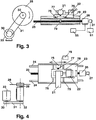
- 23 is a table which is slidably suspended in two guides 24 and can be displaced on these by means of a helical spindle 25 engaging a nut 79, which is fixedly connected with the table 23.
- the helical spindle 25 is driven by a stepmotor 26 with associated stepmotor driver 55.
- An encoder 27 corresponding to the encoder 7 in Fig. 2 is coupled to the stepmotor 26.
- a transverse table 78 is provided on top of the table 23 and is guided for displacement transversely of the table 23 by means of two guides 75.
- the transverse movement is established by means of a helical spindle 77 engaging a screw thread in the transverse table and driven by a stepmotor 76 with associated stepmotor driver 79.
- the transverse table 78 carries a vice 22, in which a specimen 21 is shown to be clamped.
- abrasive cutting wheel 28 is an abrasive cutting wheel fixedly mounted on a shaft 29 which is rotatably mounted in stationary bearings, not shown, and is driven through a wedge section belt drive 30,31,32 from a cutting motor 33.
- the specimen 21 is thus movable relative to the cutting wheel 28 in two directions perpendicular to one another, viz. in the feeding direction parallel to the cutting wheel 28, in the following referred to as the Y-direction, and in the transverse direction perpendicularly to the cutting wheel, in the following referred to as the X-direction.
- stepmotor 76 is immmobilized in the position to which it has latest been moved, as described below.
- the cutting operation is therefore equivalent for this embodiment and that of Fig. 1 and 2, and will in the following be explained in detail with reference to Fig. 5.
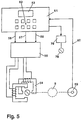
- 51 is an electronic data processor serving to adjust, co-ordinate and display the parameters of the cutting operation, partly by direct key entry, partly by calling a program stored in the processor 51, as mentioned below.
- the processor 51 has a keyboard 52 and a display 53.
- 54 represents the stepmotor 6 and 26 shown in Figs. 1,2 and 3,4, respectively.
- 55 is a stepmotor driver for the stepmotor 54.
- the processor 51 is connected with the stepmotor driver 55 through output signal conductors 56 for pulse frequency, 57 for current value of the pulses, and 58 for direction of rotation of the stepmotor, and with an encoder 59, representing the encoder 7 and 27 of Figs. 1,2 and 3,4, respectively, through an input signal conductor 60 for position.
- the encoder 59 is shown by dotted lines to be coupled to the gear 5 provided in the embodiment of Figs. 1 and 2.
- the encoder registers in the processor 51 the number of actual feeding steps of the stepmotor 54 and thereby the relative position of the cutting wheel 8,28 and the specimen 16,21 in the feeding direction (the Y-direction) as counted from a reference position, so that one or more positions can be re-established.
- the processor 51 is arranged to permit preselection of a tentative value of the feeding speed and a maximum permissible value of the feeding force.
- the selection of the maximum permissible value of the feeding force takes place by selection of a maximum permissible current value of the pulses supplied by the stepmotor driver 55 to the stepmotor 54.
- the processor automatically starts a counting of the actual feeding steps registered by the encoder during a predetermined time interval and on this basis calculates the actual value of the feeding speed. Both the tentative and the actual feeding speed are shown in the display, and if the actual feeding speed is less than the tentative, the operator can enter a new selection of the feeding speed and can in this manner make an approach to an optimum value, as previously mentioned.
- An important element of the invention is the above mentioned intermittent cutting, where the processor is so arranged as to be capable of commanding the stepmotor alternately to stop and execute one or more feeding steps, or alternately to execute one or more reverse steps and a greater number of feeding steps.
- the processor is so arranged as to be capable of commanding the stepmotor alternately to stop and execute one or more feeding steps, or alternately to execute one or more reverse steps and a greater number of feeding steps.
- the feeding movement of the cutting wheel is either stopped or reversed, whereafter the ensuing feeding motion will produce a momentaneously higher pressure in the cutting area, and the above mentioned effect is achieved.
- the stepmotor as a feeding means offers special facilities for an efficient intermittent cutting, because both stepwise feeding, stop and stepwise reverse movement can be better controlled than with other types of motors.
- the second stepmotor 76 in the embodiment of Figs. 3 and 4 serves to displace the specimen 21 a preselected number of steps relative to the cutting wheel 28 in a direction perpendicular to the cutting wheel (the X-direction) from one cutting position to a next one.
- the selected number of steps as e.g. expressed in mm, is entered into the processor 51 by the operator, whereby the stepmotor driver 79 is activated to transmit the required number of pulses to the stepmotor 76 and then to stop it.
- Each step can e.g. amount to 0.005 mm. Thereby it becomes possible to cut off samples of a preselected height in the X-direction with very high precision.
- the operator may perform an idle run in which the free end of the specimen 21 is moved past the cutting wheel 28 without touching it.
- the idle run can be observed through a window in the cabinet of the apparatus.
- the operator may by actuating a command store the Y-position registered by the encoder 27 in a memory of the processor 51 as a starting position for subsequent cutting operations, and when the contour of the specimen has just left the contour of the cutting wheel, the operator may similarly by actuating a command store the Y-position in the memory as an end position for the cutting operations.
- the processor may be so arranged that simultaneously with the storage of the end position it returns the specimen to the starting position.
- the operator may first upon entering a number of X-steps perform a clean cutting operation, and thereafter, as above described, a cutting of one or more samples having the preselected height in the X-direction, each time starting in the stored starting position and ending in the stored end position.
- the specimen Before each withdrawal in the Y-direction from the end position to the starting position the specimen may be automatically retracted a few steps in the X-direction, so that it will not interfere with the cutting wheel.
- Figs. 6 and 7 differs from that of Figs. 3 and 4 in that the helical spindle 25 engages a nut 72 which is slidably mounted in the table 23. Attached to the nut 72 is a resilient bridge 71, the ends of which are engaged between fixed stops 73 in the interior of the table 23. The bridge is provided with a strain gauge 70 which is influenced by the bending of the bridge 71 and thereby produces a voltage which is a direct measure of the force at which the specimen 21 is fed towards the cutting wheel 28.
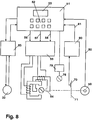
- Fig. 8 The diagram of Fig. 8 for the embodiment of Figs. 6 and 7 corresponds largely to that of Fig. 5. It shows, however, that the strain gauge 70 is connected to the processor 51 through an analog-digital converter 80 and an input conductor 81. In the processor the feeding force measured by the strain gauge is compared with a preselected maximum permissible value of the feeding force as expressed in force units. The processor is thereby caused to send an order to the stepmotor driver to change the current value of the pulses to the stepmotor 54 until the return signal from the strain gauge shows that the directly measured value of the feeding force is lower than the preselected value, but as closely up to this as possible. When the current value of the pulses has been established in this manner, the apparatus functions in the same way as that of Figs. 3 and 4. This also applies to the displacement of the specimen in the X-direction by means of the stepmotor 76, and the feeding and reverse movement in the Y-direction between the starting position and the end position of a cutting operation by means of the stepmotor
- Figs. 6 and 7 has the advantage over that of Figs. 3 and 4 that it is possible to work at a feeding force very close to the maximum value which the specimen and the cutting disc can withstand without suffering injury, and at a correspondingly high value of the feeding speed.
- FIG. 8 illustrates that a power meter 85 is inserted in a supply circuit for the cutting motor, controlled by the processor 51, the power meter in turn sending a measure signal back to the processor 51.
- the power meter 85 is inserted in a supply circuit for the cutting motor, controlled by the processor 51, the power meter in turn sending a measure signal back to the processor 51.
- the power of the cutting motor 33 in accordance with predetermined values stored in the processor 51 and, if desired, upon exceeding a maximum permissible value of the power, to stop the cutting operation and produce a visual and/or acoustic error signal.
- a specimen 101 is clamped to an arm 103 by means of clamping bolts 102.
- the arm 103 is adapted to be swung in a direction towards and away from a fixedly mounted cutting wheel 104.
- the arm 103 is attached to a shaft 106, which is rotatably and displaceably mounted in a stationary bearing 107.
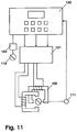
- the shaft 106 carries a gear wheel 109 meshing with a gear wheel 108 mounted on the shaft of a first stepmotor 105 to which current pulses are supplied from an associated stepmotor driver 121.
- This is controlled from an electronic data processor 120 in exactly the same manner as the stepmotor driver 55 and the processor 51 in the embodiment of Figs. 3, 4 and 5.
- the gear wheel 108 also meshes with a gear wheel 110, to which a potentiometer 111 is connected.
- the latter has a stationary output contact, which is connected to the processor and thereby enters a voltage value representing the angle of rotation of the arm 103 from a reference position, and thereby the position of the arm in the Y-direction.
- a second stepmotor 112 For moving the arm 103 in the X-direction, i.e. perpendicularly to the cutting wheel 104, a second stepmotor 112 is provided, the associated stepmotor driver 122 of which is controlled by the processor 120.
- a helical spindle 113 connected to the stepmotor engages a nut 115.
- This carries a pin 116 which extends into a rectilinear guide 136 and thereby prevents the nut 115 from rotating.
- the stepwise rotation of the stepmotor 112 in one direction and the other the nut 115 is thereby displaced axially forth and back.
- a microswitch 117 At each end of the guide a microswitch 117 is arranged. These form end stops for the axial movement of the nut 115 by interrupting the current supply to the stepmotor 112.
- the shaft 106 rests against the front end of the nut 115 through matching spherical surfaces 137, one of which is convex, and the other concave.
- the shaft 106 is kept in contact with the nut 115 by a spring 118, so that it follows the nut when this is retracted.
- the two bearings 107 and 114 need not necessarily be precisely co-axial, whereby the construction of the apparatus is simplified. Also in other respects the constructional arrangement of the apparatus is simplified.
- the operator may, by means of the stepmotors 105 and 112, begin by performing an idle run in which the starting and end positions in the Y-direction for a cutting operation are determined by observation and are stored in the processor 120 on the basis of the voltage value from the potentiometer, which here takes over the function of the encoder 59, whereafter the stepmotor 112 is used for displacement of the arm 113 in the X-direction and thereby for the cutting of one or more samples within the limits determined by the end stops formed by the microswitches 117.
- the maximum permissible feeding force is determined by entering a maximum permissible current value of the pulses supplied by the stepmotor driver 121 to the stepmotor 105.
- the specimen instead of being clamped in a fixed vice or the like, may in a manner known per se be clamped in a holder imparting to it a rotary or oscillating movement parallel to the cutting wheel, as the cutting operation proceeds. This will contribute towards gentle treatment of the specimen and the cutting wheel, because the cutting position is constantly moved. Besides it becomes possible to cut samples with a larger cross-sectional dimension relative to the diameter of the cutting wheel.
Landscapes
- Engineering & Computer Science (AREA)
- Mechanical Engineering (AREA)
- Human Computer Interaction (AREA)
- Manufacturing & Machinery (AREA)
- Physics & Mathematics (AREA)
- General Physics & Mathematics (AREA)
- Automation & Control Theory (AREA)
- Sampling And Sample Adjustment (AREA)
- Finish Polishing, Edge Sharpening, And Grinding By Specific Grinding Devices (AREA)
Description
- Fig. 1
- is a schematic side view of a first embodiment of an apparatus according to the invention,
- Fig. 2
- is a top view of same,
- Fig. 3
- is a schematic side view of a second embodiment of an apparatus according to the invention, partly in section,
- Fig. 4
- is a top view of same,
- Fig. 5
- is an electric diagram for the two embodiments of Figs. 1,2 and 3,4,
- Fig. 6
- is a schematic side view of a third embodiment of an apparatus according to the invention, partly in section,
- Fig. 7
- is a top view of same,
- Fig. 8
- is an electric diagram for the embodiment of Fig. 7,
- Fig. 9
- is a schematic side view of a fourth embodiment of an apparatus according to the invention,
- Fig. 10
- is a top view of same, and
- Fig. 11
- is an electric diagram for the embodiment of Figs. 9,10.
Claims (14)
- Apparatus for cutting off materialographic samples from a specimen (16,21,101), comprising an abrasive cutting wheel (8,28,104) driven by a cutting motor (12,33), and feeding means for advancing the cutting wheel relative to the specimen or vice versa, characterized in that the feeding means for advancing the cutting wheel in a direction (Y-direction) parallel to said wheel comprise a stepmotor (6,26,54,105) to which current pulses are supplied from an associated stepmotor driver (55,121).
- Apparatus as in claim 1, characterized in that it comprises an electronic data processor (51,120) for adjusting, co-ordinating and displaying the parameters of the abrasive cutting operation.
- Apparatus as in claim 2, characterized in that the processor (51,120) is arranged to permit preselection of a tentative value of the feeding speed and a maximum permissible value of the feeding force.
- Apparatus as in claim 3, characterized in that the preselected maximum permissible value of the feeding force is represented by a preselected maximum permissible current value of the pulses supplied by the stepmotor driver (55,121) to the stepmotor (6,26,54,105).
- Apparatus as in claim 3, characterized in that it comprises a strain gauge (70) for directly measuring the feeding force and a connection (80,81) for entering the measured value into the processor (51) for comparison with a preselected maximum permissible value of the feeding force as expressed in force units.
- Apparatus as in any of claims 3-5, characterized in that it comprises an encoder (7,27,59) coupled to the stepmotor (6,26,54) and provided with an electric connection (60) to the processor (51) for registering therein the number of actual feeding steps of the stepmotor (6,26,54) and thereby the relative position of the cutting wheel (8,28) and the specimen (16,21) in the feeding direction (the Y-direction) as counted from a reference position.
- Apparatus as in claim 6, characterized in that the processor (51) is so arranged that, when a tentative value of the feeding speed is entered, it starts a calculation of the actual feeding speed based on the number of actual feeding steps registered by the encoder (7,27,59) during a predetermined time interval.
- Apparatus as in claim 7, characterized in that the processor (51,120) is arranged to adjust the number of revolutions of the stepmotor (6,26,54,105) and thereby the feeding speed in dependence on the preselected maximum permissible value of the feeding force.
- Apparatus as in any of claims 2-8, characterized in that the processor (51,120) is so arranged as to be capable of commanding the stepmotor (6,26,54,105) alternately to stop and execute one or more feeding steps, or alternately to execute one or more reverse steps and a greater number of feeding steps.
- Apparatus as in any of claims 2-9, characterized in that it comprises means (85) for measuring the instantaneous value of the power of the cutting motor (33) and a connection for entering the measured value into the processor (51) for comparison with preselected values of the power of the cutting motor (33).
- Apparatus as in claim 2, characterized in that the processor (51,120) is arranged to execute a programmed adjustment of the torque, the number of revolutions per time unit, and the direction of rotation of the stepmotor (6,26,54,105) during the progress of the cutting operation.
- Apparatus as in claim 11, characterized in that the processor (51,120) comprises a memory for storing a plurality of programs for different materials, including identification of a suitable abrasive cutting wheel.
- Apparatus according to any of claims 2-12, characterized in that it comprises a second stepmotor (76,112) for displacing the specimen (21,101) and the cutting wheel (28,104) a preselected number of steps relative to one another prependicularly to the cutting wheel (28,104) (the X-direction) from one cutting position to a next one.
- Apparatus as in claim 13, characterized in that the specimen (101) is clamped to an arm (103), which is fixed to a shaft (106), which is rotatably and axially displaceably mounted in a fixed bearing (107) and is adapted to be rotated by means of a first stepmotor (105) in the Y-direction for swinging the arm (103) towards and away from a fixedly mounted cutting wheel (104), and to be displaced in the X-direction, i.e. perpendicularly to the cutting wheel (104) by means of a second stepmotor (112).
Applications Claiming Priority (4)
| Application Number | Priority Date | Filing Date | Title |
|---|---|---|---|
| DK160/94 | 1994-02-07 | ||
| DK16094 | 1994-02-07 | ||
| DK16094 | 1994-02-07 | ||
| PCT/DK1995/000054 WO1995021043A1 (en) | 1994-02-07 | 1995-02-06 | Apparatus for cutting off materialographic samples from a specimen |
Publications (2)
| Publication Number | Publication Date |
|---|---|
| EP0743889A1 EP0743889A1 (en) | 1996-11-27 |
| EP0743889B1 true EP0743889B1 (en) | 1998-01-07 |
Family
ID=8090442
Family Applications (1)
| Application Number | Title | Priority Date | Filing Date |
|---|---|---|---|
| EP95909653A Expired - Lifetime EP0743889B1 (en) | 1994-02-07 | 1995-02-06 | Apparatus for cutting off materialographic samples from a specimen |
Country Status (4)
| Country | Link |
|---|---|
| EP (1) | EP0743889B1 (en) |
| JP (1) | JPH09508326A (en) |
| DE (1) | DE69501394T2 (en) |
| WO (1) | WO1995021043A1 (en) |
Cited By (1)
| Publication number | Priority date | Publication date | Assignee | Title |
|---|---|---|---|---|
| EP3414050B1 (en) | 2016-02-09 | 2022-07-27 | ATM Qness GmbH | Parting machine |
Families Citing this family (5)
| Publication number | Priority date | Publication date | Assignee | Title |
|---|---|---|---|---|
| WO2010126678A2 (en) * | 2009-05-01 | 2010-11-04 | Illinois Tool Works Inc. | Improved abrasive saw |
| CZ303208B6 (en) * | 2011-03-15 | 2012-05-23 | Exactcut S. R. O. | Circular saw and saw for severing section bars |
| CN106624137A (en) * | 2017-02-08 | 2017-05-10 | 泰州市畅通管业有限公司 | Twined pipe cutting machine |
| CN112405193A (en) * | 2020-11-21 | 2021-02-26 | 江苏赛愽智能制造研究院有限公司 | Casting polishing cutting machine and polishing method thereof |
| DE102024118755B3 (en) * | 2024-07-02 | 2025-09-18 | Uniflex - Hydraulik GmbH | Machine for cutting hoses |
Family Cites Families (6)
| Publication number | Priority date | Publication date | Assignee | Title |
|---|---|---|---|---|
| GB916849A (en) * | 1960-08-10 | 1963-01-30 | Alexander Roy Bradshaw | Improved cutting machine |
| US3467075A (en) * | 1966-12-05 | 1969-09-16 | Paul O Cary | Hand operated sectioning machine |
| DE2204491C3 (en) * | 1972-01-31 | 1981-02-26 | Siemens Ag, 1000 Berlin Und 8000 Muenchen | Measurement control of a silicon saw via an auxiliary spindle |
| US4424649A (en) * | 1981-08-24 | 1984-01-10 | Buehler Ltd. | Abrasive cutter |
| US4827672A (en) * | 1987-04-27 | 1989-05-09 | Buehler Ltd. | Abrasive cutting wheel system |
| US4903437A (en) * | 1987-07-31 | 1990-02-27 | Mitsubishi Kinzoku Kabushiki Kaisha | Slicing machine for cutting semiconductor material |
-
1995
- 1995-02-06 EP EP95909653A patent/EP0743889B1/en not_active Expired - Lifetime
- 1995-02-06 JP JP7520327A patent/JPH09508326A/en not_active Ceased
- 1995-02-06 DE DE69501394T patent/DE69501394T2/en not_active Expired - Lifetime
- 1995-02-06 WO PCT/DK1995/000054 patent/WO1995021043A1/en not_active Ceased
Cited By (2)
| Publication number | Priority date | Publication date | Assignee | Title |
|---|---|---|---|---|
| EP3414050B1 (en) | 2016-02-09 | 2022-07-27 | ATM Qness GmbH | Parting machine |
| US11660719B2 (en) | 2016-02-09 | 2023-05-30 | Atm Gmbh | Parting machine, workpiece positioning device |
Also Published As
| Publication number | Publication date |
|---|---|
| WO1995021043A1 (en) | 1995-08-10 |
| JPH09508326A (en) | 1997-08-26 |
| DE69501394D1 (en) | 1998-02-12 |
| DE69501394T2 (en) | 1998-07-16 |
| EP0743889A1 (en) | 1996-11-27 |
Similar Documents
| Publication | Publication Date | Title |
|---|---|---|
| US5115403A (en) | Workpiece workability detection method and a method for cutting a workpiece by means of a cutting machine utilizing that method | |
| CA2262611A1 (en) | Disc-microtome | |
| CN111390272A (en) | Double-end saw cutting machine assembly | |
| US4918993A (en) | Method of gauging pre-existing in-situ stress from an extracted sample | |
| CN110202426A (en) | Single vision on-line checking tool grinding system and method | |
| EP0329087A1 (en) | Method and device for dressing an inner peripheral blade in a slicing machine | |
| WO1995021043A1 (en) | Apparatus for cutting off materialographic samples from a specimen | |
| US4160439A (en) | Cutting-off machine for hard bodies | |
| EP1923686A2 (en) | Device for treating a sample | |
| DE102017215951B4 (en) | machine tool | |
| EP1178869B1 (en) | Method of and apparatus for removing material | |
| CN108500383A (en) | A kind of environment-friendly type cutter device | |
| US5349847A (en) | Releasable stationary plate for rheometer | |
| JPS5942217A (en) | Device for positioning saw edge of saw working machine | |
| DE68918540T2 (en) | Grinding machine and method and device for controlling a grinding process. | |
| CN215967556U (en) | Small machining center for machining valve shell | |
| US4191078A (en) | Wire cutting flying shear | |
| CN219417109U (en) | Simple testing device for cutting sheet | |
| CN210305997U (en) | Portable pipe fitting cutting device | |
| CN207971833U (en) | A kind of crystal bar size detecting device for polysilicon block processing integrated machine | |
| CN216264549U (en) | Polishing and edge sawing equipment for plate processing | |
| CN223733953U (en) | Automatic change cutting device | |
| CN206154046U (en) | Ability individual movement's high speed grinder | |
| JP2958006B2 (en) | Method of detecting machinability of work material and method of cutting work material by cutting machine | |
| CN119260076B (en) | Automatic pipe cutting machine and control system and control method thereof |
Legal Events
| Date | Code | Title | Description |
|---|---|---|---|
| PUAI | Public reference made under article 153(3) epc to a published international application that has entered the european phase |
Free format text: ORIGINAL CODE: 0009012 |
|
| AK | Designated contracting states |
Kind code of ref document: A1 Designated state(s): DE FR GB |
|
| 17P | Request for examination filed |
Effective date: 19960518 |
|
| GRAG | Despatch of communication of intention to grant |
Free format text: ORIGINAL CODE: EPIDOS AGRA |
|
| 17Q | First examination report despatched |
Effective date: 19970318 |
|
| GRAG | Despatch of communication of intention to grant |
Free format text: ORIGINAL CODE: EPIDOS AGRA |
|
| GRAG | Despatch of communication of intention to grant |
Free format text: ORIGINAL CODE: EPIDOS AGRA |
|
| GRAH | Despatch of communication of intention to grant a patent |
Free format text: ORIGINAL CODE: EPIDOS IGRA |
|
| GRAH | Despatch of communication of intention to grant a patent |
Free format text: ORIGINAL CODE: EPIDOS IGRA |
|
| GRAA | (expected) grant |
Free format text: ORIGINAL CODE: 0009210 |
|
| AK | Designated contracting states |
Kind code of ref document: B1 Designated state(s): DE FR GB |
|
| REF | Corresponds to: |
Ref document number: 69501394 Country of ref document: DE Date of ref document: 19980212 |
|
| ET | Fr: translation filed | ||
| PLBE | No opposition filed within time limit |
Free format text: ORIGINAL CODE: 0009261 |
|
| STAA | Information on the status of an ep patent application or granted ep patent |
Free format text: STATUS: NO OPPOSITION FILED WITHIN TIME LIMIT |
|
| 26N | No opposition filed | ||
| REG | Reference to a national code |
Ref country code: GB Ref legal event code: IF02 |
|
| PGFP | Annual fee paid to national office [announced via postgrant information from national office to epo] |
Ref country code: DE Payment date: 20140129 Year of fee payment: 20 |
|
| PGFP | Annual fee paid to national office [announced via postgrant information from national office to epo] |
Ref country code: FR Payment date: 20140211 Year of fee payment: 20 |
|
| PGFP | Annual fee paid to national office [announced via postgrant information from national office to epo] |
Ref country code: GB Payment date: 20140206 Year of fee payment: 20 |
|
| REG | Reference to a national code |
Ref country code: DE Ref legal event code: R071 Ref document number: 69501394 Country of ref document: DE |
|
| REG | Reference to a national code |
Ref country code: GB Ref legal event code: PE20 Expiry date: 20150205 |
|
| PG25 | Lapsed in a contracting state [announced via postgrant information from national office to epo] |
Ref country code: GB Free format text: LAPSE BECAUSE OF EXPIRATION OF PROTECTION Effective date: 20150205 |