EP0743730A1 - Cabinet for electrical apparatus - Google Patents
Cabinet for electrical apparatus Download PDFInfo
- Publication number
- EP0743730A1 EP0743730A1 EP96410043A EP96410043A EP0743730A1 EP 0743730 A1 EP0743730 A1 EP 0743730A1 EP 96410043 A EP96410043 A EP 96410043A EP 96410043 A EP96410043 A EP 96410043A EP 0743730 A1 EP0743730 A1 EP 0743730A1
- Authority
- EP
- European Patent Office
- Prior art keywords
- support
- rail
- electrical
- cover
- electrical switchgear
- Prior art date
- Legal status (The legal status is an assumption and is not a legal conclusion. Google has not performed a legal analysis and makes no representation as to the accuracy of the status listed.)
- Granted
Links
Images


Classifications
-
- H—ELECTRICITY
- H02—GENERATION; CONVERSION OR DISTRIBUTION OF ELECTRIC POWER
- H02B—BOARDS, SUBSTATIONS OR SWITCHING ARRANGEMENTS FOR THE SUPPLY OR DISTRIBUTION OF ELECTRIC POWER
- H02B1/00—Frameworks, boards, panels, desks, casings; Details of substations or switching arrangements
- H02B1/26—Casings; Parts thereof or accessories therefor
- H02B1/40—Wall-mounted casings; Parts thereof or accessories therefor
- H02B1/42—Mounting of devices therein
-
- H—ELECTRICITY
- H02—GENERATION; CONVERSION OR DISTRIBUTION OF ELECTRIC POWER
- H02B—BOARDS, SUBSTATIONS OR SWITCHING ARRANGEMENTS FOR THE SUPPLY OR DISTRIBUTION OF ELECTRIC POWER
- H02B1/00—Frameworks, boards, panels, desks, casings; Details of substations or switching arrangements
- H02B1/26—Casings; Parts thereof or accessories therefor
- H02B1/30—Cabinet-type casings; Parts thereof or accessories therefor
- H02B1/32—Mounting of devices therein
Definitions
- the invention relates to an electrical switchgear box comprising a bottom intended to be fixed to a wall, a rail-shaped support for receiving modular electrical switchgear, and a cover for protecting said electrical switchgear.
- Known switchgear boxes have a bottom and walls on which one or more supports are fixed.
- the supports are generally symmetrical rails held at the bottom or on the walls by fixing screws.
- Modular electrical devices are fixed by removable fixing devices on the rails. They are positioned perpendicular to the bottom of the boxes.
- the front faces of electrical appliances appear on the front faces of the boxes arranged parallel to the bottom of the box.
- This arrangement allows easy installation and connection of electrical devices in the cabinets. Certain electrical devices comprising operating or display members are also easily usable if the front faces are visible.
- the object of the invention is to provide an electrical switchgear cabinet for occupying a reduced projecting volume and allowing easy attachment and connection of electrical devices.
- this object is achieved by the fact that a pivoting fixing device for fixing the support on the bottom, the pivoting of the support taking place along an axis parallel to the bottom of the box, the support being arranged substantially perpendicular to the plane of the melts in a normal position for use.
- the length of the support is less than the dimension of the electrical equipment corresponding to the distance between a rear face intended to be fixed on the support and a front face.
- the cover has a lateral opening on a face perpendicular to the bottom, said opening allowing accessibility to the front face of the apparatus.
- the support is a symmetrical rail.
- the pivoting fixing device comprises at least one clip disposed on the bottom of the box, an axis associated with the support and intended to be held by said clips, and stops arranged perpendicular to said axis to block movement of the support.
- the bottom is made of insulating plastic, the clips being molded with said bottom.
- the support, the axis, and the stops form, preferably, a single molded plastic part.
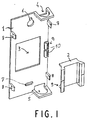
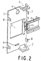
- Figures 1 and 2 show two views of a bottom and a support according to an embodiment of the invention.
- Figure 3 shows a view of a bottom according to the embodiment of Figure 1 and a support of different dimensions.
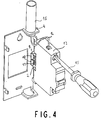
- Figure 4 shows the installation and connection of a device in a box according to Figure 3.
- Figure 5 shows a cabinet according to Figure 3 with the electrical appliance installed in its normal position of use.
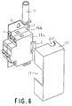
- Figure 6 shows a cabinet according to Figures 1 and 2 comprising an installed electrical appliance and a protective cover.
- the box according to an embodiment of the invention of Figure 1 has a bottom 1 intended to be fixed on a wall and a support 2 in the form of a symmetrical rail.
- the bottom 1 has an opening 3 and passages 4 and 5 for receiving arrivals or departures of electrical conduits.
- fixing the bottom to a wall, for example a wall or a partition. is made through two orifices 6 and 7.
- Lugs 8 arranged at the ends of the plate forming the bottom 1 participate in the fixing of a cover of the box.
- the support 2 in the form of a symmetrical rail has a length allowing it to receive two modular devices or one device having the width of 2 modules.
- the width of a module is generally around 18mm or 9mm.
- the support 2 is fixed to the bottom 1 using a pivoting device 9.
- the device 9 comprises a fixed part, composed for example of clips 10 preferably arranged on the edge of the bottom plate, and of a mobile part.
- the mobile part is constituted by an axis 11 which is clipped into the fixed part as shown in Figure 2. All longitudinal movement is blocked by stops 12 arranged perpendicular to the axis 11. Two stops are located at the ends of the axis 11 and one on its central part.
- the support 2 pivots relative to the bottom 1 around the axis 11 of rotation, parallel to said bottom 1 and to the fixing wall.
- Figure 3 shows a bottom according to the embodiment of Figures 1 and 2, and a support 2 having the dimensions of a single module.
- Figure 4 shows the installation and connection of an electrical device in a box having a bottom 1 and a support 2 according to Figure 3.
- the fixing is done. preferably when the support is deployed so that the device 13 is perpendicular to the bottom. In this position, the connection of an electrical conductor 14 is facilitated.
- An elongated tool like a screwdriver 15 can be used without difficulty.
- the conductor 14 arrives, in this example. by a conduit 16 crossing the passage 4.
- the device 13 When the connection is completed, the device 13 can be arranged in its normal position of use. the electrical appliance is then folded towards the bottom of the box thanks to the pivoting of the support 2 relative to the bottom 1.
- Figure 5 shows the cabinet and the apparatus of Figure 4 in its normal position of use.
- the bottom 1 is fixed by a screw 17 against a wall 18 of a wall.
- the support 2 which has pivoted vertically along an axis parallel to the bottom 1 is in a position substantially perpendicular to said bottom and to the wall.
- the apparatus is in a position where it is pressed parallel to the bottom, with a lateral face parallel to the wall 18.
- the projecting volume occupied by the cabinet is very small. It depends on the width of the device or the length of the support. In known boxes, the occupied surface projection depended on the height of the apparatus, the height being the distance between the rear face of the apparatus which is fixed on the support and the accessible front face.
- the front of the electrical device In its normal position, the front of the electrical device remains accessible, which allows a user to operate it or view it.
- the electrical appliance is protected by a cover 19 which covers the entire enclosure.
- the cover is fixed and maintained by the lugs 8.
- FIG. 6 shows an exploded view of a box, according to an embodiment of the invention, comprising a support 2 supporting two electrical devices 13a and 13b.
- the cover 19, for covering the two devices and the bottom of the box, has a notch 20 for the passage of the conduit 16 and an opening 21 to make the front faces of the devices accessible.
- the support 2 has a length making it possible to support one or two modular electrical devices. However, it is possible to use in boxes according to the invention supports of greater length.
- the pivoting fastening device described above preferably comprises a fixed part in the form of clips and a mobile part in the form of an axis. In other embodiments of the invention it is possible to reverse the fixed and mobile parts. It is also possible to use other systems allowing pivoting between the support and the bottom.
- the support 2 is preferably a plastic rail, but it may be made of any other material, for example metal.
- the shape of a symmetrical rail can also be replaced by any other form of support, for example asymmetrical rails.
Abstract
Description
L'invention concerne un coffret d'appareillage électrique comportant un fond destiné à être fixé à une paroi, un support en forme de rail pour recevoir de l'appareillage électrique modulaire, et un capot pour protéger ledit appareillage électrique.The invention relates to an electrical switchgear box comprising a bottom intended to be fixed to a wall, a rail-shaped support for receiving modular electrical switchgear, and a cover for protecting said electrical switchgear.
Les coffrets d'appareillage connus comportent un fond et des parois sur lesquels sont fixés un ou plusieurs supports. Les supports sont généralement des rails symétriques maintenues au fond ou sur les parois par des vis de fixation. Des appareils électriques modulaires sont fixés par des dispositifs de fixation amovibles sur les rails. Ils sont positionnés perpendiculairement au fond des coffrets. Les faces avant des appareils électriques apparaissent sur les faces avant des coffrets disposées parallèlement au fond du boîtier.Known switchgear boxes have a bottom and walls on which one or more supports are fixed. The supports are generally symmetrical rails held at the bottom or on the walls by fixing screws. Modular electrical devices are fixed by removable fixing devices on the rails. They are positioned perpendicular to the bottom of the boxes. The front faces of electrical appliances appear on the front faces of the boxes arranged parallel to the bottom of the box.
Cette disposition permet une installation et un raccordement faciles des appareils électriques dans les coffrets. Certains appareils électriques comportant des organes de manoeuvre ou de visualisation sont aussi facilement utilisables si les faces avant sont visibles.This arrangement allows easy installation and connection of electrical devices in the cabinets. Certain electrical devices comprising operating or display members are also easily usable if the front faces are visible.
Lorsque les coffrets d'appareillage électrique doivent se trouver dans des endroits peu accessibles, la disposition classique des appareils n'est plus satisfaisante. Les avantages d'une installation aisée et d'un raccordement facile ne sont plus évidents. Il en est de même lorsque le volume occupé en saillie par les coffrets doit être réduit, et ne doit pas dépasser des dimensions prédéfinies. Des coffrets connus, notamment ceux prévus pour être encastrés permettent de réduire le volume occupé, en saillie, mais leur mise en oeuvre n'est pas facile et rapide.When the electrical switchgear boxes must be in inaccessible places, the conventional arrangement of the devices is no longer satisfactory. The benefits of easy installation and easy connection are no longer evident. It is the same when the volume occupied projecting by the boxes must be reduced, and must not exceed predefined dimensions. Known boxes, in particular those intended to be built-in make it possible to reduce the occupied volume, projecting, but their implementation is not easy and quick.
L'invention a pour but un coffret d'appareillage électrique permettant d'occuper un volume en saillie, réduit et permettant une fixation et des raccordements aisés des appareils électriques.The object of the invention is to provide an electrical switchgear cabinet for occupying a reduced projecting volume and allowing easy attachment and connection of electrical devices.
Selon l'invention, ce but est atteint par le fait que un dispositif de fixation pivotant pour fixer le support sur le fond, le pivotement du support se faisant selon un axe parallèle au fond du coffret, le support étant disposé sensiblement perpendiculairement au plan du fond dans une position normale d'utilisation.According to the invention, this object is achieved by the fact that a pivoting fixing device for fixing the support on the bottom, the pivoting of the support taking place along an axis parallel to the bottom of the box, the support being arranged substantially perpendicular to the plane of the melts in a normal position for use.
Selon un mode préférentiel de réalisation, la longueur du support est inférieure à la dimension de l'appareillage électrique correspondant à la distance entre une face arrière destinée à être fixée sur le support et une face avant.According to a preferred embodiment, the length of the support is less than the dimension of the electrical equipment corresponding to the distance between a rear face intended to be fixed on the support and a front face.
Dans un mode particulier de réalisation, le capot comporte une ouverture latérale sur une face perpendiculaire au fond , ladite ouverture permettant l'accessibilité à la face avant de l'appareillage.In a particular embodiment, the cover has a lateral opening on a face perpendicular to the bottom, said opening allowing accessibility to the front face of the apparatus.
De préférence, le support est un rail symétrique.Preferably, the support is a symmetrical rail.
Selon un développement de l'invention, le dispositif de fixation pivotant comporte au moins un clips disposé sur le fond du coffret, un axe associé au support et destiné à être maintenu par ledit clips, et des butées disposées perpendiculairement audit axe pour bloquer les déplacements longitudinaux du support.According to a development of the invention, the pivoting fixing device comprises at least one clip disposed on the bottom of the box, an axis associated with the support and intended to be held by said clips, and stops arranged perpendicular to said axis to block movement of the support.
Selon un mode de réalisation du développement de l'invention le fond est en matière plastique isolante, les clips étant moulés avec ledit fond. Le support, l'axe, et les butées forment, de préference, une seule pièce moulée en matière plastique.According to one embodiment of the development of the invention, the bottom is made of insulating plastic, the clips being molded with said bottom. The support, the axis, and the stops form, preferably, a single molded plastic part.
D'autres avantages et caractéristiques ressortiront plus clairement de la description qui va suivre, de modes particuliers de réalisation de l'invention, donnés à titre d'exemples non limitatifs, et représentés aux dessins annexés sur lesquels :Other advantages and characteristics will emerge more clearly from the description which follows, of particular embodiments of the invention, given by way of nonlimiting examples, and represented in the appended drawings in which:
Les figures 1 et 2 montrent deux vues d'un fond et d'un support selon un mode de réalisation de l'invention.Figures 1 and 2 show two views of a bottom and a support according to an embodiment of the invention.
La figure 3 montre une vue d'un fond selon le mode de réalisation de la figure 1 et d'un support de dimensions différentes.Figure 3 shows a view of a bottom according to the embodiment of Figure 1 and a support of different dimensions.
La figure 4 montre l'installation et le raccordement d'un appareil dans un coffret selon la figure 3.Figure 4 shows the installation and connection of a device in a box according to Figure 3.
La figure 5 montre un coffret selon la figure 3 avec l'appareil électrique installé dans sa position normale d'utilisation.Figure 5 shows a cabinet according to Figure 3 with the electrical appliance installed in its normal position of use.
La figure 6 montre un coffret selon les figures 1 et 2 comportant un appareil électrique installé et un capot de protection.Figure 6 shows a cabinet according to Figures 1 and 2 comprising an installed electrical appliance and a protective cover.
Le coffret selon un mode de réalisation de l'invention de la figure 1 comporte un fond 1 destiné à être fixé sur une paroi et un support 2 en forme de rail symétrique. le fond 1 comporte une ouverture 3 et des passages 4 et 5 pour recevoir des arrivées ou des départs de conduits électriques. la fixation du fond sur une paroi, par exemple un mur ou une cloison. se fait à travers deux orifices 6 et 7. Des ergots 8 disposés à des extrémités de la plaque formant le fond 1 participent à la fixation d'un capot du coffret.The box according to an embodiment of the invention of Figure 1 has a
Le support 2 en forme de rail symétrique a une longueur lui permettant de recevoir deux appareils modulaires ou un appareil ayant la largeur de 2 modules. La largeur d'un module est généralement de l'ordre de 18mm ou 9mm. Le support 2 est fixé sur le fond 1 à l'aide d'un dispositif pivotant 9.The
Le dispositif 9 comporte une partie fixe, composée par exemple de clips 10 disposés de préférence en bordure de la plaque de fond, et d'une partie mobile. La partie mobile est constituée par un axe 11 qui s'enclipse dans la partie fixe comme représenté sur la figure 2. Tout mouvement longitudinal est bloqué par des butées 12 disposées perpendiculairement à l'axe 11. Deux butées sont situées aux extrémités de l'axe 11 et une sur sa partie centrale.The device 9 comprises a fixed part, composed for example of
Le support 2 pivote par rapport au fond 1 autour de l'axe 11 de rotation, parallèlement audit fond 1 et à la paroi de fixation.The
Le mode particulier de réalisation de la partie fixe 10, sous la forme de clips permet d'interchanger des supports 2 et de les adapter rapidement au type d'appareil électrique à installer. la figure 3 montre un fond selon le mode de réalisation des figures 1 et 2, et un support 2 ayant les dimensions d'un seul module.The particular embodiment of the
La figure 4 montre l'installation et le raccordement d'un appareil électrique dans un coffret ayant un fond 1 et un support 2 selon la figure 3. Un appareil électrique 13, pouvant être par exemple, un disjoncteur ou un interrupteur, est fixé sur le support 2.Figure 4 shows the installation and connection of an electrical device in a box having a
La fixation se fait. de préférence lorsque le support est déployé de manière à ce que l'appareil 13 se trouve perpendiculairement au fond. Dans cette position, le raccordement d'un conducteur électrique 14 est facilité. Un outil de forme allongé comme un tournevis 15 peut être utilisé sans difficulté. Le conducteur 14 arrive, dans cet exemple. par un conduit 16 traversant le passage 4.The fixing is done. preferably when the support is deployed so that the
Lorsque le raccordement est terminé, l'appareil 13 peut-être disposé dans sa position normale d'utilisation. l'appareil électrique est alors rabattu vers le fond du coffret grâce au pivotement du support 2 par rapport au fond 1.When the connection is completed, the
La figure 5 montre le coffret et l'appareillage de la figure 4 dans sa position normale d'utilisation. Le fond 1 est fixé par une vis 17 contre une paroi 18 d'un mur.Figure 5 shows the cabinet and the apparatus of Figure 4 in its normal position of use. The
Le support 2 qui a pivoté verticalement selon un axe parallèle au fond 1 se trouve dans une position sensiblement perpendiculaire audit fond et à la paroi. L'appareillage est dans une position où il est plaqué parallèlement au fond, avec une face latérale parallèle à la paroi 18. Le volume en saillie occupé par le coffret est très faible. Il dépend de la largeur de l'appareillage ou de la longueur du support. Dans des coffrets connus le volume occupé en saillie dépendait de la hauteur de l'appareillage, la hauteur étant la distance entre la face arrière de l'appareillage qui se fixe sur le support et la face avant accessible.The
Dans sa position normale la face avant de l'appareil électrique reste accessible, ce qui permet à un utilisateur de le manoeuvrer ou de le visualiser.In its normal position, the front of the electrical device remains accessible, which allows a user to operate it or view it.
La protection de l'appareil électrique est assurée par un capot 19 qui coiffez l'ensemble du coffret. le capot est fixé et maintenu par les ergots 8.The electrical appliance is protected by a cover 19 which covers the entire enclosure. the cover is fixed and maintained by the
La figure 6 montre une vue éclatée d'un coffret, selon un mode de réalisation de l'invention, comportant un support 2 supportant deux appareils électriques 13a et 13b. le capot 19, permettant de coiffer les deux appareils et le fond du coffret, comporte une encoche 20 pour le passage du conduit 16 et une ouverture 21 pour rendre accessible les faces avant des appareils.FIG. 6 shows an exploded view of a box, according to an embodiment of the invention, comprising a
Dans les modes de réalisation décrits ci-dessus, le support 2 a une longueur permettant de supporter un ou deux appareils électriques modulaires. Mais, il est possible d'utiliser dans des coffrets selon l'invention des supports de longueur supérieure.In the embodiments described above, the
Le dispositif de fixation pivotant décrit ci-dessus comporte, de préférence, une partie fixe en forme de clips et une partie mobile en forme d'axe. Dans d'autres modes de réalisation de l'invention il est possible d'inverser les parties fixes et mobiles. Il est possible aussi d'utiliser d'autres systèmes permettant le pivotement entre le support et le fond.The pivoting fastening device described above preferably comprises a fixed part in the form of clips and a mobile part in the form of an axis. In other embodiments of the invention it is possible to reverse the fixed and mobile parts. It is also possible to use other systems allowing pivoting between the support and the bottom.
Le support 2 est de préférence un rail en matière plastique, mais il peut-être en tout autre matériau, par exemple en métal. La forme d'un rail symétrique peut également être remplacée par tout autre forme de support, par exemple des rails asymétriques.The
Claims (7)
Applications Claiming Priority (2)
| Application Number | Priority Date | Filing Date | Title |
|---|---|---|---|
| FR9506073 | 1995-05-17 | ||
| FR9506073A FR2734448B1 (en) | 1995-05-17 | 1995-05-17 | ELECTRICAL EQUIPMENT BOX |
Publications (2)
| Publication Number | Publication Date |
|---|---|
| EP0743730A1 true EP0743730A1 (en) | 1996-11-20 |
| EP0743730B1 EP0743730B1 (en) | 2001-10-24 |
Family
ID=9479252
Family Applications (1)
| Application Number | Title | Priority Date | Filing Date |
|---|---|---|---|
| EP19960410043 Expired - Lifetime EP0743730B1 (en) | 1995-05-17 | 1996-05-02 | Cabinet for electrical apparatus |
Country Status (4)
| Country | Link |
|---|---|
| EP (1) | EP0743730B1 (en) |
| DE (1) | DE69616145T2 (en) |
| ES (1) | ES2164857T3 (en) |
| FR (1) | FR2734448B1 (en) |
Cited By (3)
| Publication number | Priority date | Publication date | Assignee | Title |
|---|---|---|---|---|
| FR2885457A1 (en) * | 2005-05-04 | 2006-11-10 | Legrand France | Box or panel type distribution enclosure, has mounting clip and incoming contacts conformed so that cut out apparatuses placed on socket are in flattened position in which apparatus main side faces screw terminal |
| US8780534B2 (en) | 2011-09-21 | 2014-07-15 | Schneider Electric USA, Inc. | Swing out mount |
| CN105667336A (en) * | 2016-03-08 | 2016-06-15 | 上海埃而生电气有限公司 | Modularized intelligent high-voltage distribution box |
Citations (4)
| Publication number | Priority date | Publication date | Assignee | Title |
|---|---|---|---|---|
| DE1926280U (en) * | 1965-06-25 | 1965-11-04 | Licentia Gmbh | FASTENING DEVICE FOR NARROW INSTALLATION EQUIPMENT. |
| DE1993996U (en) * | 1968-05-04 | 1968-09-19 | Bbc Brown Boveri & Cie | DEVICE SUPPORT RAIL FOR SUPPORTING INSTALLATION EQUIPMENT. |
| DE2952619A1 (en) * | 1979-12-28 | 1981-07-09 | Mainland Elektro-, Sanitär- und Eisenwaren-Großhandels GmbH, 8772 Marktheidenfeld | Insulated housing for electric equipment - has removable frame with vertical angles carrying horizontal members made to standard specifications |
| EP0352149A1 (en) * | 1988-07-04 | 1990-01-24 | Telemecanique | Supporting device for electrical apparatuses |
-
1995
- 1995-05-17 FR FR9506073A patent/FR2734448B1/en not_active Expired - Fee Related
-
1996
- 1996-05-02 EP EP19960410043 patent/EP0743730B1/en not_active Expired - Lifetime
- 1996-05-02 ES ES96410043T patent/ES2164857T3/en not_active Expired - Lifetime
- 1996-05-02 DE DE1996616145 patent/DE69616145T2/en not_active Expired - Fee Related
Patent Citations (4)
| Publication number | Priority date | Publication date | Assignee | Title |
|---|---|---|---|---|
| DE1926280U (en) * | 1965-06-25 | 1965-11-04 | Licentia Gmbh | FASTENING DEVICE FOR NARROW INSTALLATION EQUIPMENT. |
| DE1993996U (en) * | 1968-05-04 | 1968-09-19 | Bbc Brown Boveri & Cie | DEVICE SUPPORT RAIL FOR SUPPORTING INSTALLATION EQUIPMENT. |
| DE2952619A1 (en) * | 1979-12-28 | 1981-07-09 | Mainland Elektro-, Sanitär- und Eisenwaren-Großhandels GmbH, 8772 Marktheidenfeld | Insulated housing for electric equipment - has removable frame with vertical angles carrying horizontal members made to standard specifications |
| EP0352149A1 (en) * | 1988-07-04 | 1990-01-24 | Telemecanique | Supporting device for electrical apparatuses |
Cited By (3)
| Publication number | Priority date | Publication date | Assignee | Title |
|---|---|---|---|---|
| FR2885457A1 (en) * | 2005-05-04 | 2006-11-10 | Legrand France | Box or panel type distribution enclosure, has mounting clip and incoming contacts conformed so that cut out apparatuses placed on socket are in flattened position in which apparatus main side faces screw terminal |
| US8780534B2 (en) | 2011-09-21 | 2014-07-15 | Schneider Electric USA, Inc. | Swing out mount |
| CN105667336A (en) * | 2016-03-08 | 2016-06-15 | 上海埃而生电气有限公司 | Modularized intelligent high-voltage distribution box |
Also Published As
| Publication number | Publication date |
|---|---|
| ES2164857T3 (en) | 2002-03-01 |
| FR2734448A1 (en) | 1996-11-22 |
| DE69616145T2 (en) | 2002-06-06 |
| FR2734448B1 (en) | 1997-06-27 |
| EP0743730B1 (en) | 2001-10-24 |
| DE69616145D1 (en) | 2001-11-29 |
Similar Documents
| Publication | Publication Date | Title |
|---|---|---|
| FR2768867A1 (en) | WIRE CONTAINMENT SYSTEM FOR MOUNTING ON A WALL STRUCTURE | |
| FR2905225A1 (en) | MECHANISM OF APPARATUS TO BE INSTALLED FROM THE BACK OF AN APPARATUS SUPPORT AND ELECTRICAL EQUIPMENT COMPRISING SUCH A MECHANISM. | |
| EP0772256B1 (en) | Electrical apparatus with connection terminals protected by a diaphragm comprising wings | |
| EP0743730B1 (en) | Cabinet for electrical apparatus | |
| FR2769404A1 (en) | HOUSING FOR AN ELECTRICAL APPARATUS SUCH AS A CIRCUIT BREAKER | |
| EP1134768B1 (en) | Starter motor assembly | |
| FR2738676A1 (en) | Connection terminal with protective diaphragm to screw fixing for use in modular electric equipment | |
| EP1146619B1 (en) | Frame upright serving as a conduit for distributing electrical energy | |
| EP3503318B1 (en) | Power distribution device in particular in a cabinet or an electrical panel | |
| EP0355233B1 (en) | Insulated junction box, especially for mounting in luminaire supports | |
| FR2797356A1 (en) | Range-extending terminal block for electricity metering or control apparatus, comprises insulated terminals, fitted to apparatus' fixed terminals, for wider range of connecting cables. | |
| EP0342095B1 (en) | Device for protecting mechanically a printed circuit board, especially a chassis of colour television set | |
| EP0054478B1 (en) | Apparatus for holding elongated objects such as cables, cable bundles or the like | |
| EP3524879A1 (en) | Sealed safety lighting unit | |
| EP0743728B1 (en) | Cabinet for electrical apparatus | |
| EP0800192B1 (en) | Electric device comprising a contactor with an accommodation device for a protection module and protection module | |
| EP0860901A1 (en) | Housing for electric apparatus an electrical apparatus comprising the same | |
| FR3060880A1 (en) | DEVICE FOR DISTRIBUTING AN ELECTRICAL CURRENT WITHIN TWO AT LEAST TWO ELECTRICAL DEVICES | |
| EP1505703A1 (en) | Protection device for a junction box | |
| FR2900508A1 (en) | Metallic power distribution bus-bar for e.g. circuit-breaker, has connection units between connection terminal and stud, and allowing two configurations in which operating unit is in sides of corresponding main surfaces, respectively | |
| EP4343805A1 (en) | Protection module for a power supply input of an electrical switchgear of the nh fuse-disconnector type | |
| FR2620580A1 (en) | Supply box for electric metering | |
| EP1195858B1 (en) | Device for duct with cable fastening means | |
| BE1006966A5 (en) | Means of attaching profiled sections with at least one conductive bar andprofiled section to be used with this means of attachment | |
| FR2845835A1 (en) | CHUTE PROVIDED WITH AT LEAST ONE MEANS OF CONTINUITY OF SEPARATIONS AT THE LEVEL OF THE RIGHT OR ANGULAR JUNCTIONS |
Legal Events
| Date | Code | Title | Description |
|---|---|---|---|
| PUAI | Public reference made under article 153(3) epc to a published international application that has entered the european phase |
Free format text: ORIGINAL CODE: 0009012 |
|
| AK | Designated contracting states |
Kind code of ref document: A1 Designated state(s): DE ES GB IT |
|
| 17P | Request for examination filed |
Effective date: 19970412 |
|
| 17Q | First examination report despatched |
Effective date: 19990510 |
|
| RAP1 | Party data changed (applicant data changed or rights of an application transferred) |
Owner name: SCHNEIDER ELECTRIC INDUSTRIES SA |
|
| RAP1 | Party data changed (applicant data changed or rights of an application transferred) |
Owner name: SCHNEIDER ELECTRIC INDUSTRIES SA |
|
| GRAG | Despatch of communication of intention to grant |
Free format text: ORIGINAL CODE: EPIDOS AGRA |
|
| GRAG | Despatch of communication of intention to grant |
Free format text: ORIGINAL CODE: EPIDOS AGRA |
|
| GRAH | Despatch of communication of intention to grant a patent |
Free format text: ORIGINAL CODE: EPIDOS IGRA |
|
| GRAH | Despatch of communication of intention to grant a patent |
Free format text: ORIGINAL CODE: EPIDOS IGRA |
|
| GRAA | (expected) grant |
Free format text: ORIGINAL CODE: 0009210 |
|
| AK | Designated contracting states |
Kind code of ref document: B1 Designated state(s): DE ES GB IT |
|
| REF | Corresponds to: |
Ref document number: 69616145 Country of ref document: DE Date of ref document: 20011129 |
|
| REG | Reference to a national code |
Ref country code: GB Ref legal event code: IF02 |
|
| GBT | Gb: translation of ep patent filed (gb section 77(6)(a)/1977) |
Effective date: 20020105 |
|
| REG | Reference to a national code |
Ref country code: ES Ref legal event code: FG2A Ref document number: 2164857 Country of ref document: ES Kind code of ref document: T3 |
|
| PGFP | Annual fee paid to national office [announced via postgrant information from national office to epo] |
Ref country code: DE Payment date: 20020502 Year of fee payment: 7 |
|
| RAP2 | Party data changed (patent owner data changed or rights of a patent transferred) |
Owner name: SCHNEIDER ELECTRIC INDUSTRIES SAS |
|
| PLBE | No opposition filed within time limit |
Free format text: ORIGINAL CODE: 0009261 |
|
| STAA | Information on the status of an ep patent application or granted ep patent |
Free format text: STATUS: NO OPPOSITION FILED WITHIN TIME LIMIT |
|
| 26N | No opposition filed | ||
| PG25 | Lapsed in a contracting state [announced via postgrant information from national office to epo] |
Ref country code: DE Free format text: LAPSE BECAUSE OF NON-PAYMENT OF DUE FEES Effective date: 20031202 |
|
| PGFP | Annual fee paid to national office [announced via postgrant information from national office to epo] |
Ref country code: GB Payment date: 20120502 Year of fee payment: 17 |
|
| PGFP | Annual fee paid to national office [announced via postgrant information from national office to epo] |
Ref country code: IT Payment date: 20120512 Year of fee payment: 17 |
|
| PGFP | Annual fee paid to national office [announced via postgrant information from national office to epo] |
Ref country code: ES Payment date: 20120607 Year of fee payment: 17 |
|
| GBPC | Gb: european patent ceased through non-payment of renewal fee |
Effective date: 20130502 |
|
| PG25 | Lapsed in a contracting state [announced via postgrant information from national office to epo] |
Ref country code: IT Free format text: LAPSE BECAUSE OF NON-PAYMENT OF DUE FEES Effective date: 20130502 |
|
| PG25 | Lapsed in a contracting state [announced via postgrant information from national office to epo] |
Ref country code: GB Free format text: LAPSE BECAUSE OF NON-PAYMENT OF DUE FEES Effective date: 20130502 |
|
| REG | Reference to a national code |
Ref country code: ES Ref legal event code: FD2A Effective date: 20140609 |
|
| PG25 | Lapsed in a contracting state [announced via postgrant information from national office to epo] |
Ref country code: ES Free format text: LAPSE BECAUSE OF NON-PAYMENT OF DUE FEES Effective date: 20130503 |