EP0743275A2 - Method for controlling a multiple telescopic jib and the controlling arrangement for carrying out the method - Google Patents
Method for controlling a multiple telescopic jib and the controlling arrangement for carrying out the method Download PDFInfo
- Publication number
- EP0743275A2 EP0743275A2 EP19950107341 EP95107341A EP0743275A2 EP 0743275 A2 EP0743275 A2 EP 0743275A2 EP 19950107341 EP19950107341 EP 19950107341 EP 95107341 A EP95107341 A EP 95107341A EP 0743275 A2 EP0743275 A2 EP 0743275A2
- Authority
- EP
- European Patent Office
- Prior art keywords
- piston
- cylinder
- cylinder unit
- pressure
- unit
- Prior art date
- Legal status (The legal status is an assumption and is not a legal conclusion. Google has not performed a legal analysis and makes no representation as to the accuracy of the status listed.)
- Withdrawn
Links
Images


Classifications
-
- B—PERFORMING OPERATIONS; TRANSPORTING
- B66—HOISTING; LIFTING; HAULING
- B66C—CRANES; LOAD-ENGAGING ELEMENTS OR DEVICES FOR CRANES, CAPSTANS, WINCHES, OR TACKLES
- B66C23/00—Cranes comprising essentially a beam, boom, or triangular structure acting as a cantilever and mounted for translatory of swinging movements in vertical or horizontal planes or a combination of such movements, e.g. jib-cranes, derricks, tower cranes
- B66C23/62—Constructional features or details
- B66C23/64—Jibs
- B66C23/70—Jibs constructed of sections adapted to be assembled to form jibs or various lengths
- B66C23/701—Jibs constructed of sections adapted to be assembled to form jibs or various lengths telescopic
- B66C23/705—Jibs constructed of sections adapted to be assembled to form jibs or various lengths telescopic telescoped by hydraulic jacks
Definitions
- the invention relates to a method for controlling the telescopic extensions of a multiple telescopic boom of a crane or the like, also referred to as thrust pieces, in particular a loading crane, between the adjacent extensions of which a hydraulic piston-cylinder unit is arranged, the cylinder of which is arranged with the the immediately preceding and the immediately following piston-cylinder unit is connected via a line both on the piston side and on the piston rod side, the cylinder of the first piston-cylinder unit articulated to the fixed boom section extending to extend its piston rod its retracted state is acted upon on the piston side by a predetermined working pressure generated by a pressure source, and the piston-side application pressure of each subsequent piston-cylinder unit in its retracted state is reduced to such a value compared to the application pressure of the preceding piston-cylinder unit that each this piston-cylinder units only extends after the previous one.
- the invention further relates to a control device for carrying out the aforementioned method for the telescopic extensions of a multiple telescopic boom for a crane or the like, between the adjacent extensions of which a hydraulic piston-cylinder unit is arranged, the cylinder of which is immediately preceding and the immediately following piston-cylinder unit is connected via a line both on the piston side and on the piston rod side, the cylinder of the first piston-cylinder unit articulated to the fixed boom section being connected to the piston side via an extension line, generally via a load holding valve a pressure source is connected, and on the piston rod side with an intake line, and wherein in the piston-side connecting lines between adjacent piston-cylinder units, a biasing valve is arranged, by means of which the piston-side working pressure in the cylinder follows the piston-cylinder unit is to be reduced to a value such that the piston-side working pressure in the preceding cylinder is such that each piston-cylinder unit only extends after the previous one.
- a hydraulic piston-cylinder unit is arranged between two adjacent telescopic extensions.
- an extension is to be extended from its position retracted into the previous extension or retracted into it from a position extended from the previous extension
- the first extension (which is the largest in cross section) adjacent to the relevant extension arm via a piston-cylinder -Unit is connected to the extension arm.
- a mechanical path sequence control for the telescopic extensions of a multiple telescopic boom of a loading crane in which at the closed end of the hydraulic cylinder for the subsequent extension in the piston-side connecting line to the previous extension or its piston cylinder -A unit is arranged a shut-off valve which is closed in the retracted state of the following extension, and is opened by a stop arranged on the previous extension when the previous extension has reached its extended end position.
- a check valve is connected in parallel to the shut-off valves, which closes when the extensions are extended. If pressure is applied to the retracting line connecting the piston-cylinder units on the piston rod side, pressure oil can initially only - after opening a check valve in a return line leading from the last piston-cylinder unit to the pressure oil source - from the last piston-cylinder unit drain, but not from the other piston-cylinder units, so that the last (outermost) extension is retracted first.
- a mandrel arranged on the piston of the last (outermost) piston-cylinder unit opens its check valve, bridges the shut-off valve of the last piston-cylinder unit and thus causes hydraulic fluid from the piston-side cylinder space downstream piston-cylinder unit can flow out etc. until all piston-cylinder units and thus all extensions are retracted one after the other from the outside in.
- a generic pressure sequence control is known from its own prior public use, in which in each case in the piston-side extension line sections between adjacent piston-cylinder units a biasing valve is arranged, with which the piston-side working pressure in the cylinder of the subsequent piston-cylinder unit compared to the piston-side working pressure of the previous piston-cylinder unit is to be reduced by an amount such that each of these piston-cylinder units only extends after the previous one.
- the respective reduction in the pressurization pressure between adjacent piston-cylinder units must be considerable. B. 20%, since a slight pressure reduction of, for example, 3 or 5% would not ensure the desired sequence control.
- the piston rods of the piston-cylinder units are designed with different sizes of diameter in this known pressure sequence control, so that one can have the same cylinder diameter .
- the last piston-cylinder unit retracts first due to the greatest working pressure, then the piston-cylinder unit next to it, etc.
- the present invention has for its object to provide a generic sequence control method and a generic control device for performing this method while maintaining the advantages of a generic pressure sequence control, which can also be used for multiple telescopic booms with any number of extensions.
- the solution to this problem in procedural terms according to the invention is that the pressure reduction generated on the cylinder of a retracted piston-cylinder unit on the piston side compared to the piston side working pressure of the previous piston-cylinder unit is canceled when the piston rod is extended while the task with regard to Control device according to the invention is solved in that the series-connected preload valves are each assigned a by-pass line which is blocked until the relevant piston-cylinder unit is extended and which is to be automatically unlocked when the extended end position is reached.
- the prestressing valves provided with a by-pass line and assigned to the cylinder of a piston-cylinder unit on the piston side and on the piston rod side being formed separately or else can form a structural unit.
- a variant for the retraction control in which the cylinder of the last piston-cylinder unit is also connected to the pressure source on the piston rod side via an inlet line that is blocked when extending, consists in the fact that in the piston rod-side connecting lines between each adjacent piston-cylinder unit there is a check valve is arranged, by means of which this line to the inwardly following piston-cylinder unit is blocked until the outwardly preceding piston-cylinder unit has reached its end-of-travel position.
- FIG. 1 shows a schematic side view of a multiple telescopic boom, generally designated 1, with six extensions 2.1 to 2.6 in the fully extended state.
- the last (outermost) extension 2.6 has moved into the previous extension 2.5, this into the previous extension 2.4 u.s.f. and the first extension 2.1 into the hollow boom section 3 of an articulated arm or the like, which is therefore stationary with regard to the direction of extension or retraction.
- a piston-cylinder unit 4 is assigned to each extension 2.
- the piston-cylinder unit assigned to the first extension 2.1 4.1 is articulated with its piston rod 5.1 on the boom section 3 and attached with its cylinder 6.1 via a flange 7.1 to the outer end of the extension 2.1.
- the piston-cylinder unit 4.2 assigned to the extension 2.2 only the piston rod 5.2 can be seen in FIG. 1, since its cylinder 6.2 lies behind the cylinder 6.1, the cylinder 6.2 on the flange 7.1 and the outer end of the piston rod 5.2 on an outer end of the extension 2.2 attached flange 7.2 is attached.
- the cylinder 6.3 of the piston-cylinder unit 4.3, also fastened to the flange 7.2, for the next extension 2.3 is located behind the piston rod 5.2. Its piston rod 5.3 is attached to a flange 7.3 fastened to the outer end of the extension 2.3, to which in turn the cylinder 6.4 of the piston-cylinder unit 4.4 for the next extension 2.4 is also attached, the piston rod 5.4 of which is attached to one at the end of the next extension 2.4 attached flange 7.4 is articulated, and so on.
- Such (or similar) arrangement of the piston-cylinder units 4 is made in order to be able to arrange and accommodate them in a suitable manner, since a piston-cylinder unit 4 is arranged in each case between adjacent extensions 2 must be, and the piston-cylinder units must not only be arranged in a suitable manner in the extended position shown, but also in the retracted position of the boom section 3, in which the flanges 7.1-7.6 are directly adjacent to each other.
- the telescopic boom 1 should be controlled so that when entering from the position shown in FIG. 1, the last (outermost) extension 2.6 first moves into the inward extension 2.5, then the (extension 2.6 containing) extension 2.5 in the previous ones Extension 2.4 etc.
- control should ensure that when extending, only the first extension 2.1 extends from the boom section 3, only then the second extension 2.2 from the extension 2.1 and the like.
- FIG. 2 shows a circuit diagram for a control device which ensures a corresponding sequential control for the extension, FIG. 2 showing an intermediate state in which the three piston-cylinder units 4.1-4.3 have already been extended and have reached their extended end position, while the following piston-cylinder units 4.4-4.6 (and thus their extensions 2.4-2.6) are still retracted.
- Fig. 2 it can be seen that the cylinder 6.1 of the first piston-cylinder unit 4.1 on the piston side is connected via an extension line 9.1 provided with a load-holding valve 8 to a pressure source 10, so that the cylinder 6.1 takes the extension 2.1 out of it Extends (not shown) inserted position when the extension line 9 is pressurized.
- adjacent piston-cylinder units 4 are each connected, inter alia, on the piston side to an extension line 9.n, namely the cylinder 6.1 with the cylinder 6.2 via a line 9.2, the cylinder 6.2 with the cylinder 6.3 via a line 9.3 etc., all cylinders become 6 is pressurized when the line section 9.1 leading from the pressure source 10 to the first piston-cylinder unit 4.1 is pressurized.
- the piston-side working pressure in the individual cylinders gradually decreases from the first piston-cylinder unit 4.1 to the last piston-cylinder unit 4.6, because the piston-cylinder units on the piston side connecting line sections 9.2, 9.3 etc., a preload valve 11 is connected which reduces the working pressure in the subsequent cylinder 6 compared to the working pressure in the preceding cylinder 6 on the piston side, reference being made at this point to the fact that the preload valves of the piston-cylinder Units 4.2-4.5 are each assigned a by-pass 12, which is closed when the assigned piston-cylinder unit is not yet fully extended, as is still the case in FIG. 2 with respect to the by-pass lines 12.4 and 12.5 is, and which is opened upon reaching the extended end position of the respective piston-cylinder unit 4 with the activation of the associated bias valve 11.
- the piston-side working pressure in the first cylinder 6.1 is 200 bar and the preload valves 11 reduce the working pressure in the following cylinder by 50 bar, for example, the working pressure in the second cylinder 6.2 is only 150 bar, in the third cylinder 6.3 only 100 bar and so on.
- any number of piston-cylinder units 4 or extensions 2 can be provided.
- the activation means 13 are arranged in the circuit diagram according to FIG. 2 as mechanical means, but they can also be of an electrical or hydraulic type, for example.
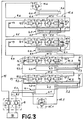
- FIG. 3 the arrangement with regard to the extension corresponds to the configuration according to FIG. 2.
- the same or equivalent parts are provided with the same reference numerals, with FIG. 3 again showing a state in which the first three piston-cylinder units 4.1-4.3 are (already) extended, while the last three piston-cylinder units 4.4-4.6 are (still) retracted.
- the inlet line 15, which is led from the pressure source 10 via the load holding valve 8 to the piston-cylinder units 4 and which is pressurized to retract the extended extensions 2 or their piston-cylinder units 4, is not in this embodiment to the first piston-cylinder unit 4.1, but to the last piston-cylinder unit 4.6, so that its cylinder 6.6 in the fully extended state (not shown) (like this in FIG. 3 with respect to the piston-cylinder units 4.1. -4.3 is shown), pressure is applied to the piston rod side via a line section 15.6 and is the first to enter. This is achieved in that the same arrangement has been made in the entry line branch as with respect to the exit arrangement.
- the inlet line 15 is pressurized, the last piston-cylinder unit 4.6 moves in first because the greatest working pressure is applied to it on the piston rod side, while the working pressure of the piston-cylinder unit 4.5 following inwards through the preload valve 11 ' .5 is reduced, the piston rod-side working pressure in the subsequent cylinder is further reduced, etc. If, however, a piston-cylinder unit that precedes the outside is now completely retracted, the inward biasing valve 11 'is activated via the by-pass 12' assigned to it, as in FIG. 3 between the piston-cylinder units 4.4 and 4.3 becomes clear.
- FIG. 4 shows the circuit arrangement according to FIG. 3 with simultaneous assignment to the representation according to FIG. 1 in a different representation for the purpose of further clarification, but all piston-cylinder units in accordance with FIG. 1 being fully extended.
- FIG. 5 shows a further variant of a sequence control according to the invention in a representation as a switching arrangement, which corresponds to the extension control with the configurations according to FIGS. 2 and 3 and with regard to the configuration of the piston-cylinder units 4 with the configuration according to FIG. 3. Furthermore, it also corresponds to the control system according to FIG. 3 insofar as the inlet line 15 is led from the pressure source 10 to the last piston-cylinder unit 4.6. It differs from the embodiment according to FIG.
- both the preload valves 11 and 11 'and the shut-off valves 16 are each assigned a check valve 17 which is blocked in the normal operational flow direction and connected in parallel.
Abstract
Description
Die Erfindung betrifft ein Verfahren zum Steuern der auch als Schubstücke bezeichneten Teleskop-Ausschübe eines Mehrfach-Teleskopauslegers eines Krans od. dgl., insbesondere eines Ladekrans, zwischen dessen einander benachbarten Ausschüben jeweils eine hydraulische Kolben-Zylinder-Einheit angeordnet ist, deren Zylinder mit der unmittelbar vorhergehenden und der unmittelbar nachfolgenden Kolben-Zylinder-Einheit sowohl kolbenseitig als auch kolbenstangenseitig jeweils über eine Leitung verbunden ist, wobei der Zylinder der an den festen Auslegerabschnitt angelenkten ersten Kolben-Zylinder-Einheit zum Ausfahren ihrer Kolbenstange aus ihrem eingefahrenen Zustand kolbenseitig mit einem von einer Druckquelle erzeugten, vorgegebenen Arbeitsdruck beaufschlagt wird, und der kolbenseitige Beaufschlagungsdruck jeder nachfolgenden Kolben-Zylinder-Einheit in deren eingefahrenem Zustand gegenüber dem Beaufschlagungsdruck der vorhergehenden Kolben-Zylinder-Einheit auf einen solchen Wert reduziert wird, daß jede dieser Kolben-Zylinder-Einheiten erst nach der vorherigen ausfährt.The invention relates to a method for controlling the telescopic extensions of a multiple telescopic boom of a crane or the like, also referred to as thrust pieces, in particular a loading crane, between the adjacent extensions of which a hydraulic piston-cylinder unit is arranged, the cylinder of which is arranged with the the immediately preceding and the immediately following piston-cylinder unit is connected via a line both on the piston side and on the piston rod side, the cylinder of the first piston-cylinder unit articulated to the fixed boom section extending to extend its piston rod its retracted state is acted upon on the piston side by a predetermined working pressure generated by a pressure source, and the piston-side application pressure of each subsequent piston-cylinder unit in its retracted state is reduced to such a value compared to the application pressure of the preceding piston-cylinder unit that each this piston-cylinder units only extends after the previous one.
Die Erfindung betrifft weiterhin eine Steuereinrichtung zur Durchführung des vorgenannten Verfahrens für die Teleskop-Ausschübe eines Mehrfach-Teleskopauslegers für einen Kran od. dgl., zwischen dessen einander benachbarten Ausschüben jeweils eine hydraulische Kolben-Zylinder-Einheit angeordnet ist, deren Zylinder mit der unmittelbar vorhergehenden und der unmittelbar nachfolgenden Kolben-Zylinder-Einheit sowohl kolbenseitig als auch kolbenstangenseitig jeweils über eine Leitung verbunden ist, wobei der Zylinder der an den festen Auslegerabschnitt angelenkten ersten Kolben-Zylinder-Einheit - im allgemeinen über ein Last-Halteventil - kolbenseitig über eine Ausfahrleitung mit einer Druckquelle verbunden ist, und kolbenstangenseitig mit einer Einfahrleitung, und wobei in den kolbenseitigen Verbindungsleitungen zwischen einander benachbarten Kolben-Zylinder-Einheiten jeweils ein Vorspannventil angeordnet ist, mittels dessen der kolbenseitige Arbeitsdruck im Zylinder der nachfolgenden Kolben-Zylinder-Einheit gegenüber dem kolbenseitigen Arbeitsdruck im vorhergehenden Zylinder auf einen solchen Wert zu reduzieren ist, daß jede Kolben-Zylinder-Einheit erst nach der vorhergehenden ausfährt.The invention further relates to a control device for carrying out the aforementioned method for the telescopic extensions of a multiple telescopic boom for a crane or the like, between the adjacent extensions of which a hydraulic piston-cylinder unit is arranged, the cylinder of which is immediately preceding and the immediately following piston-cylinder unit is connected via a line both on the piston side and on the piston rod side, the cylinder of the first piston-cylinder unit articulated to the fixed boom section being connected to the piston side via an extension line, generally via a load holding valve a pressure source is connected, and on the piston rod side with an intake line, and wherein in the piston-side connecting lines between adjacent piston-cylinder units, a biasing valve is arranged, by means of which the piston-side working pressure in the cylinder follows the piston-cylinder unit is to be reduced to a value such that the piston-side working pressure in the preceding cylinder is such that each piston-cylinder unit only extends after the previous one.
Bei Mehrfach-Teleskopauslegern von Kranen od. dgl. ist jeweils zwischen zwei einander benachbarten Teleskop-Ausschüben eine hydraulische Kolben-Zylinder-Einheit angeordnet, mittels welcher ein Ausschub aus seiner in den vorhergehenden Ausschub eingefahrenen Stellung auszufahren bzw. aus einer aus dem vorhergehenden Ausschub ausgefahrenen Stellung wieder in diesen einzufahren ist, wobei der im ausgefahrenen Zustand dem betreffenden Auslegerarm benachbarte erste (im Querschnitt größte) Ausschub über eine Kolben-Zylinder-Einheit mit dem Auslegerarm verbunden ist.In the case of multiple telescopic booms of cranes or the like, a hydraulic piston-cylinder unit is arranged between two adjacent telescopic extensions. by means of which an extension is to be extended from its position retracted into the previous extension or retracted into it from a position extended from the previous extension, the first extension (which is the largest in cross section) adjacent to the relevant extension arm via a piston-cylinder -Unit is connected to the extension arm.
Dabei ist es wünschenswert mittels einer Folgesteuerung sicherzustellen, daß beim Ausfahren zunächst der dem Auslegerarm benachbarte erste (im Querschnitt größte) Ausschub ausfährt, danach erst der zweite Ausschub etc. und zuletzt der letzte (im Querschnitt kleinste) Ausschub, und daß beim Einfahren die Reihenfolge umgekehrt ist.It is desirable to use a sequential control system to ensure that when the extension is extended, the first extension (which is the largest in cross-section) extends next to the extension arm, then only the second extension, etc. and finally the last (smallest in cross-section), and that the sequence when moving in is reversed.
Aus der WO 93/08116 ist eine mechanische Weg-Folgesteuerung für die Teleskop-Ausschübe eines Mehrfach-Teleskopauslegers eines Ladekrans bekannt, bei welcher jeweils am geschlossenen Ende des Hydraulikzylinders für den nachfolgende Ausschub in der kolbenseitigen Verbindungsleitung zum vorhergehenden Ausschub bzw. deren Kolben-Zylinder-Einheit ein Absperrventil angeordnet ist, welches im eingefahrenen Zustand des nachfolgenden Ausschubes geschlossen ist, und von einem am vorhergehenden Ausschub angeordneten Anschlag geöffnet wird, wenn der vorhergehende Ausschub seine Ausfahr-Endposition erreicht hat. Wenn zum Ausfahren des eingefahrenen Teleskopauslegers eine von der Druckölquelle zur ersten Kolben-Zylinder-Einheit führende Ausfahrleitung mit Druck beaufschlagt wird, fährt daher zunächst nur die erste Kolben-Zylinder-Einheit mit dem mit ihr verbundenen ersten Ausschub aus bis dieser seine Ausfahr-Endposition erreicht hat und dabei das Absperrventil zur nächsten Kolben-Zylinder-Einheit mittels eines Anschlages öffnet, so daß nunmehr auch die zweite Kolben-Zylinder-Einheit kolbenseitig mit Drucköl beaufschlagt wird und ausfahren kann u.s.f.From WO 93/08116 a mechanical path sequence control for the telescopic extensions of a multiple telescopic boom of a loading crane is known, in which at the closed end of the hydraulic cylinder for the subsequent extension in the piston-side connecting line to the previous extension or its piston cylinder -A unit is arranged a shut-off valve which is closed in the retracted state of the following extension, and is opened by a stop arranged on the previous extension when the previous extension has reached its extended end position. If an extension line leading from the pressure oil source to the first piston-cylinder unit is pressurized to extend the retracted telescopic boom, only the first piston-cylinder unit with the first extension connected to it extends until it reaches its final extension position has and thereby opens the shut-off valve to the next piston-cylinder unit by means of a stop, so that now the second piston-cylinder unit is also acted upon by pressure oil on the piston side will and can extend etc.
Zum Einfahren der Ausschübe ist zu den Absperrventilen jeweils ein Rückschlagventil parallel geschaltet, welches beim Ausfahren schließt. Wird zum Einfahren Druck auf eine die Kolben-Zylinder-Einheiten kolbenstangenseitig verbindende Einfahrleitung gegeben, so kann Drucköl zunächst nur - nach Öffnung eines Rückschlagventils in einer von der letzten Kolben-Zylinder-Einheit zur Druckölquelle führenden Rückleitung - aus der letzten Kolben-Zylinder-Einheit abfließen, nicht aber aus den übrigen Kolben-Zylinder-Einheiten, so daß der letzte (äußerste) Ausschub zuerst eingefahren wird. Hat dieser seine Einfahr-Endposition erreicht, so öffnet ein am Kolben der letzten (äußersten) Kolben-Zylinder-Einheit angeordneter Dorn deren Rückschlagventil, überbrückt dabei das Absperrventil der letzten Kolben-Zylinder-Einheit und bewirkt so, daß Hydraulikflüssigkeit aus dem kolbenseitigen Zylinderraum der nach innen nachfolgenden Kolben-Zylinder-Einheit abfließen kann u.s.f. bis alle Kolben-Zylinder-Einheiten und damit sämtliche Ausschübe nacheinander von außen nach innen eingefahren sind.To retract the extensions, a check valve is connected in parallel to the shut-off valves, which closes when the extensions are extended. If pressure is applied to the retracting line connecting the piston-cylinder units on the piston rod side, pressure oil can initially only - after opening a check valve in a return line leading from the last piston-cylinder unit to the pressure oil source - from the last piston-cylinder unit drain, but not from the other piston-cylinder units, so that the last (outermost) extension is retracted first. If this has reached its retracted end position, a mandrel arranged on the piston of the last (outermost) piston-cylinder unit opens its check valve, bridges the shut-off valve of the last piston-cylinder unit and thus causes hydraulic fluid from the piston-side cylinder space downstream piston-cylinder unit can flow out etc. until all piston-cylinder units and thus all extensions are retracted one after the other from the outside in.
Abgesehen davon, daß bei dieser Weg-Folgesteuerung die Anordnung der Ventile örtlich im wesentlichen festgelegt ist, was ggf. zu konstruktiven Schwierigkeiten führen kann, ist es nachteilig, daß die vor ihrem jeweiligen Ausfahren vom Öldruck abgesperrten Kolben-Zylinder-Einheiten während des Betriebes keine Sicherungsfunktion übernehmen können.In addition to the fact that with this path sequence control, the arrangement of the valves is essentially fixed locally, which can possibly lead to constructional difficulties, it is disadvantageous that the piston-cylinder units, which are shut off from the oil pressure before their respective extension, do not have any during operation Can take over security function.
Aus einer eigenen offenkundigen Vorbenutzung ist eine gattungsgemäße Druck-Folgesteuerung bekannt, bei welcher in den kolbenseitigen Ausfahrleitungsabschnitten zwischen einander benachbarten Kolben-Zylinder-Einheiten jeweils ein Vorspannventil angeordnet ist, mit dem der kolbenseitige Arbeitsdruck im Zylinder der jeweils nachfolgenden Kolben-Zylinder-Einheit gegenüber dem kolbenseitigen Arbeitsdruck der vorhergehenden Kolben-Zylinder-Einheit beim Ausfahren jeweils um einen solchen Wert zu reduzieren ist, daß jede dieser Kolben-Zylinder-Einheiten erst nach der vorherigen ausfährt. Um eine definierte Folgesteuerung in der oben erwähnten Reihenfolge zu erzielen, muß die jeweilige Reduzierung des Beaufschlagungsdruckes zwischen einander benachbarten Kolben-Zylinder-Einheiten erheblich sein, also z. B. 20 % betragen, da eine lediglich geringfügige Druckreduzierung von bspw. 3 oder 5 % die angestrebte Folgesteuerung nicht sicherstellen würde.A generic pressure sequence control is known from its own prior public use, in which in each case in the piston-side extension line sections between adjacent piston-cylinder units a biasing valve is arranged, with which the piston-side working pressure in the cylinder of the subsequent piston-cylinder unit compared to the piston-side working pressure of the previous piston-cylinder unit is to be reduced by an amount such that each of these piston-cylinder units only extends after the previous one. In order to achieve a defined sequential control in the order mentioned above, the respective reduction in the pressurization pressure between adjacent piston-cylinder units must be considerable. B. 20%, since a slight pressure reduction of, for example, 3 or 5% would not ensure the desired sequence control.
Obwohl diese bekannte Druck-Folgesteuerung bei entsprechender Druckreduzierung zwischen einander benachbarten Kolben-Zylinder-Einheiten zuverlässig arbeitet und dabei u. a. ermöglicht, daß durch sie während des Betriebes auch Absicherungsfunktionen wahrgenommen werden können, ist sie insoweit nachteilig, als die Anzahl der Ausschübe aufgrund der von innen nach außen von Kolben-Zylinder-Einheit zu Kolben-Zylinder-Einheit stufenweisen Reduzierung des Ausfahr-Beaufschlagungsdruckes begrenzt ist. Steht nämlich bspw. an der ersten Kolben-Zylinder-Einheit ein Arbeitsdruck von 280 bar zur Verfügung und sind bei fünf Ausschüben vier Vorspannventile vorhanden, die jeweils auf bspw. 70 bar eingestellt sind, so würde der letzten Kolben-Zylinder-Einheit kein Druck mehr zur Verfügung stehen.Although this known pressure sequence control works reliably with a corresponding pressure reduction between adjacent piston-cylinder units and thereby u. a. enables that they can also perform safety functions during operation, it is disadvantageous insofar as the number of extensions is limited due to the gradual reduction of the extension pressure from inside to outside from piston-cylinder unit to piston-cylinder unit . For example, if a working pressure of 280 bar is available on the first piston-cylinder unit and there are four preload valves on five extensions, each of which is set to 70 bar, for example, the last piston-cylinder unit would no longer have any pressure be available.
Um auch beim Einfahren der Ausschübe die gewünschte Reihenfolge von außen nach innen sicherzustellen, wenn Druck auf die Einfahrleitung gegeben wird, sind bei dieser bekannten Druck-Folgesteuerung die Kolbenstangen der Kolben-Zylinder-Einheiten mit unterschiedlich großem Durchmesser ausgebildet, so daß man bei gleichem Zylinderdurchmesser, wie er schon aus Wirtschaftlichkeitsgründen regelmäßig gewählt wird, zu entsprechend unterschiedlich großen Kolben-Ringflächen (= Kolbenfläche abzgl. der Kolbenstangen-Querschnittsfläche) kommt, wobei die Kolbenstange der dem festen Auslegerabschnitt benachbarten ersten Kolben-Zylinder-Einheit den größten und die Kolbenstange der letzten Kolben-Zylinder-Einheit den kleinsten Durchmesser (und damit bei gleichem Zylinderdurchmesser die größte Kolbenringfläche) aufweist. Das hat zur Folge, daß die letzte Kolben-Zylinder-Einheit aufgrund des größten Arbeitsdrukkes zuerst einfährt, danach die ihr benachbarte Kolben-Zylinder-Einheit u.s.f. Dabei ist es nachteilig, daß auch insoweit die Anzahl der Ausschübe begrenzt ist, weil die Knickfestigkeit bei einem zu kleinen Kolbenstangendurchmesser nicht mehr ausreicht, wie er bei Vielfach-Teleskopauslegern vorgesehen werden müßte, um erhebliche Unterschiede der Kolbenringflächen einander benachbarter Kolben-Zylinder-Einheiten zu erreichen und damit die gewünschte Einfahr-Reihenfolge sicherzustellen.In order to ensure the desired sequence from the outside to the inside when the extensions are retracted, when pressure is applied to the inlet line, the piston rods of the piston-cylinder units are designed with different sizes of diameter in this known pressure sequence control, so that one can have the same cylinder diameter , As it is regularly chosen for reasons of economy, piston ring surfaces of different sizes (= piston surface minus the piston rod cross-sectional area) are obtained, the piston rod of the first piston-cylinder unit adjacent to the fixed boom section being the largest and the piston rod of the last pistons -Cylinder unit has the smallest diameter (and thus the largest piston ring area with the same cylinder diameter). As a result, the last piston-cylinder unit retracts first due to the greatest working pressure, then the piston-cylinder unit next to it, etc. It is disadvantageous that the number of extensions is limited because the kink resistance of one too small a piston rod diameter is no longer sufficient, as it would have to be provided in multiple telescopic booms, in order to achieve considerable differences in the piston ring surfaces of adjacent piston-cylinder units and thus to ensure the desired retraction order.
Der vorliegenden Erfindung liegt die Aufgabe zugrunde, unter Aufrechterhaltung der Vorteile einer gattungsgemäßen Druck-Folgesteuerung ein gattungsgemäßes Folgesteuerverfahren sowie eine gattungsgemäße Steuereinrichtung zur Durchführung dieses Verfahrens zu schaffen, die auch für Vielfach-Teleskopausleger mit einer beliebigen Anzahl von Ausschüben verwendbar sind.The present invention has for its object to provide a generic sequence control method and a generic control device for performing this method while maintaining the advantages of a generic pressure sequence control, which can also be used for multiple telescopic booms with any number of extensions.
Die Lösung dieser Aufgabe besteht in verfahrensmäßiger Hinsicht erfindungsgemäß darin, daß die am Zylinder einer eingefahrenen Kolben-Zylinder-Einheit kolbenseitig erzeugte Druckreduzierung gegenüber dem kolbenseitigen Arbeitsdruck der vorhergehenden Kolben-Zylinder-Einheit aufgehoben wird, wenn die Kolbenstange ausgefahren ist, während die Aufgabe hinsichtlich der Steuereinrichtung erfindungsgemäß dadurch gelöst wird, daß den in Reihe geschalteten Vorspannventilen jeweils eine By-pass-Leitung zugeordnet ist, die gesperrt ist, bis die betreffende Kolben-Zylinder-Einheit ausgefahren ist, und die bei Erreichen der Ausfahr-Endposition selbsttätig zu entsperren ist.The solution to this problem in procedural terms according to the invention is that the pressure reduction generated on the cylinder of a retracted piston-cylinder unit on the piston side compared to the piston side working pressure of the previous piston-cylinder unit is canceled when the piston rod is extended while the task with regard to Control device according to the invention is solved in that the series-connected preload valves are each assigned a by-pass line which is blocked until the relevant piston-cylinder unit is extended and which is to be automatically unlocked when the extended end position is reached.
Wie weiter unten noch im einzelnen erläutert wird, werden bei der erfindungsgemäßen Folgesteuerung bei Beaufschlagung der Ausfahrleitung mit Druck sogleich sämtliche Zylinder kolbenseitig unter Druck gesetzt, jedoch unter unterschiedlichen Arbeitsdruck, der aufgrund der vorgesehenen stufenweisen Druckreduzierung/Vorspannventile von innen nach außen abnimmt, so daß die gewünschte Ausfahrreihenfolge eingehalten wird. Hat dabei die erste Kolben-Zylinder-Einheit ihre Ausfahr-Endposition erreicht und wird demgemäß die Druckreduzierung von der ersten zur zweiten Kolben-Zylinder-Einheit durch Freischaltung des entsprechenden Vorspannventils über den ihm zugeordneten, zunächst gesperrten By-pass aufgehoben, so erhöht sich der kolbenseitige Arbeitsdruck in der zweiten Kolben-Zylinder-Einheit und den nachfolgenden Kolben-Zylinder-Einheiten entsprechend, so daß bei der erfindungsgemäßen Arbeitsweise bzw. Ausbildung mithin insoweit keine Beschränkung der Anzahl von Ausschüben mehr gegeben ist.As will be explained in more detail below, in the sequence control according to the invention, when the extension line is pressurized, all cylinders are immediately pressurized on the piston side, but under different working pressures, which decrease due to the gradual pressure reduction / preload valves provided from the inside out, so that the desired exit order is observed. If the first piston-cylinder unit has reached its extended end position and the pressure reduction from the first to the second piston-cylinder unit is accordingly canceled by activating the corresponding preload valve via the initially blocked by-pass assigned to it, this increases piston-side working pressure in the second piston-cylinder unit and the subsequent piston-cylinder units accordingly, so that there is no longer any restriction on the number of extensions in the method or design according to the invention.
Um bei einer erfindungsgemäßen Folgesteuerung auch hinsichtlich der für die Einfahrbewegung getroffenen Maßnahmen keiner Beschränkung der Anzahl der Ausschübe mehr zu unterliegen, und dabei zugleich den erheblichen wirtschaftlichen Vorteil zu erzielen, mit gleich ausgebildeten Kolben-Zylinder-Einheiten arbeiten zu können, ist gemäß einer bevorzugten Ausgestaltung vorgesehen, daß der Zylinder der letzten (äußersten) Kolben-Zylinder-Einheit kolbenstangenseitig über eine beim Ausfahren entsperrte Einfahrleitung unmittelbar mit dem Tank verbunden ist, daß in den kolbenstangenseitigen Verbindungsleitungen zwischen einander benachbarten Kolben-Zylinder-Einheiten jeweils ein Vorspannventil angeordnet ist, mittels dessen der kolbenstangenseitige Arbeitsdruck im Zylinder der nach innen nachfolgenden Kolben-Zylinder-Einheit gegenüber dem kolbenstangenseitigen Arbeitsdruck der nach außen vorhergehenden Kolben-Zylinder-Einheit auf einen solchen Wert zu reduzieren ist, daß jede Kolben-Zylinder-Einheit erst nach der nach außen vorhergehenden Kolben-Zylinder-Einheit einfährt, und daß den in Reihe geschalteten Vorspannventilen jeweils eine By-pass-Leitung zugeordnet ist, die gesperrt ist, bis die betreffende Kolben-Zylinder-Einheit eingefahren ist, und die bei Erreichen der Einfahr-Endposition selbsttätig zu entsperren ist. Bei dieser Ausgestaltung sind mithin für das Einfahren im wesentlichen die gleichen Maßnahmen vorgesehen wie für das Ausfahren, wobei die dem Zylinder einer Kolben-Zylinder-Einheit jeweils kolbenseitig und kolbenstangenseitig zugeordneten, mit einer By-pass-Leitung versehenen Vorspannventile separat ausgebildet sein oder aber auch eine Baueinheit bilden können.According to a preferred embodiment, in a sequence control according to the invention there is no longer any restriction on the number of extensions with regard to the measures taken for the retracting movement, and at the same time to achieve the considerable economic advantage of being able to work with piston-cylinder units of the same design provided that the cylinder of the last (outermost) piston-cylinder unit on the piston rod side is connected directly to the tank via an inlet line unlocked when extending, that in A preload valve is arranged on the piston rod-side connecting lines between adjacent piston-cylinder units, by means of which the piston rod-side working pressure in the cylinder of the inwardly following piston-cylinder unit compared to the piston rod-side working pressure of the previous piston-cylinder unit to such a value It is to be reduced that each piston-cylinder unit only retracts after the piston-cylinder unit that precedes the outside, and that the bypass valves connected in series are each assigned a by-pass line that is blocked until the relevant piston Cylinder unit is retracted and must be unlocked automatically when the retracted end position is reached. In this embodiment, essentially the same measures are provided for the retraction as for the extension, the prestressing valves provided with a by-pass line and assigned to the cylinder of a piston-cylinder unit on the piston side and on the piston rod side being formed separately or else can form a structural unit.
Eine Variante für die Einfahrsteuerung, bei welcher ebenfalls der Zylinder der letzten Kolben-Zylinder-Einheit kolbenstangenseitig über eine beim Ausfahren gesperrte Einfahrleitung mit der Druckquelle verbunden ist, besteht darin, daß in den kolbenstangenseitigen Verbindungsleitungen zwischen einander benachbarten Kolben-Zylinder-Einheiten jeweils ein Sperrventil angeordnet ist, mittels dessen diese Leitung zur nach innen nachfolgenden Kolben-Zylinder-Einheit gesperrt ist bis die nach außen vorhergehende Kolben-Zylinder-Einheit ihre Einfahr-Endposition erreicht hat.A variant for the retraction control, in which the cylinder of the last piston-cylinder unit is also connected to the pressure source on the piston rod side via an inlet line that is blocked when extending, consists in the fact that in the piston rod-side connecting lines between each adjacent piston-cylinder unit there is a check valve is arranged, by means of which this line to the inwardly following piston-cylinder unit is blocked until the outwardly preceding piston-cylinder unit has reached its end-of-travel position.
Weitere bevorzugte Ausgestaltungen der vorliegenden Erfindung sind in den Unteransprüchen beschrieben.Further preferred embodiments of the present invention are described in the subclaims.
Die Erfindung ist nachstehend an Ausführungsbeispielen unter Bezugnahme auf eine Zeichnung weiter erläutert. Es zeigt:
- Fig. 1
- eine schematisierte Seitenansicht eines Mehrfach-Teleskopauslegers mit sechs Ausschüben und den diesen zugeordneten Kolben-Zylinder-Einheiten;
- Fig. 2
- ein Schaltschema einer ersten Ausführungsform einer erfindungsgemäßen Steuereinrichtung;
- Fig. 3
- ein Schaltschema einer Variante einer erfindungsgemäßen Steuereinrichtung;
- Fig. 4
- eine andere Darstellung des Schaltschemas gemäß Fig. 3; und
- Fig. 5
- ein Schaltschema für eine weitere Variante einer erfindungsgemäßen Steuereinrichtung.
- Fig. 1
- a schematic side view of a multiple telescopic boom with six extensions and the associated piston-cylinder units;
- Fig. 2
- a circuit diagram of a first embodiment of a control device according to the invention;
- Fig. 3
- a circuit diagram of a variant of a control device according to the invention;
- Fig. 4
- another representation of the circuit diagram of FIG. 3; and
- Fig. 5
- a circuit diagram for a further variant of a control device according to the invention.
Fig. 1 zeigt in einer schematisierten Seitenansicht einen im ganzen mit 1 bezeichneten Mehrfach-Teleskop-Ausleger mit sechs Ausschüben 2.1 bis 2.6 im völlig ausgefahrenen Zustand. Im völlig eingefahrenen Zustand ist der letzte (äußerste) Ausschub 2.6 in den vorhergehenden Ausschub 2.5 eingefahren, dieser in den ihm vorhergehenden Ausschub 2.4 u.s.f. und der erste Ausschub 2.1 in den hohlen Auslegerabschnitt 3 eines Knickarms od. dgl., der im Hinblick auf die Ausfahr- bzw. Einfahrrichtung mithin ortsfest ist.1 shows a schematic side view of a multiple telescopic boom, generally designated 1, with six extensions 2.1 to 2.6 in the fully extended state. In the fully retracted state, the last (outermost) extension 2.6 has moved into the previous extension 2.5, this into the previous extension 2.4 u.s.f. and the first extension 2.1 into the
Jedem Ausschub 2 ist eine Kolben-Zylinder-Einheit 4 zugeordnet. Die dem ersten Ausschub 2.1 zugeordnete Kolben-Zylinder-Einheit 4.1 ist mit ihrer Kolbenstange 5.1 am Auslegerabschnitt 3 angelenkt und mit ihrem Zylinder 6.1 über einen Flansch 7.1 am äußeren Ende des Ausschubes 2.1 befestigt. Von der dem Ausschub 2.2 zugeordneten Kolben-Zylinder-Einheit 4.2 ist in Fig. 1 lediglich die Kolbenstange 5.2 erkennbar, da ihr Zylinder 6.2 hinter dem Zylinder 6.1 liegt, wobei der Zylinder 6.2 am Flansch 7.1 und das äußere Ende der Kolbenstange 5.2 an einem am äußeren Ende des Ausschubes 2.2 befestigten Flansch 7.2 befestigt ist.A piston-
Der ebenfalls am Flansch 7.2 befestigte Zylinder 6.3 der Kolben-Zylinder-Einheit 4.3 für den nächsten Ausschub 2.3 liegt hinter der Kolbenstange 5.2. Seine Kolbenstange 5.3 ist an einem am äußeren Ende des Ausschubes 2.3 befestigten Flansch 7.3 befestigt, an dem wiederum auch der Zylinder 6.4 der Kolben-Zylinder-Einheit 4.4 für den nächsten Ausschub 2.4 befestigt ist, dessen Kolbenstange 5.4 an einem am Ende des nächsten Ausschubes 2.4 befestigten Flansch 7.4 angelenkt ist u.s.f. Dabei wird eine solche (oder ähnliche) Anordnung der Kolben-Zylinder-Einheiten 4 getroffen, um sie in geeigneter Weise anordnen und unterbringen zu können, da jeweils zwischen einander benachbarten Ausschüben 2 eine Kolben-Zylinder-Einheit 4 angeordnet werden muß, und die Kolben-Zylinder-Einheiten nicht nur in der dargestellten ausgefahrenen Stellung in geeigneter Weise angeordnet sein müssen, sondern auch in der den Auslegerabschnitt 3 eingefahrenen Einfahrstellung, in welcher die Flansche 7.1-7.6 einander unmittelbar benachbart sind. Wie bereits weiter oben ausgeführt worden ist, soll der Teleskopausleger 1 so gesteuert werden, daß beim Einfahren aus der in Fig. 1 dargestellten Stellung zunächst der letzte (äußerste) Ausschub 2.6 in den nach innen vorhergehenden Ausschub 2.5 einfährt, sodann der (den Ausschub 2.6 enthaltende) Ausschub 2.5 in den nach innen vorhergehenden Ausschub 2.4 u.s.f.The cylinder 6.3 of the piston-cylinder unit 4.3, also fastened to the flange 7.2, for the next extension 2.3 is located behind the piston rod 5.2. Its piston rod 5.3 is attached to a flange 7.3 fastened to the outer end of the extension 2.3, to which in turn the cylinder 6.4 of the piston-cylinder unit 4.4 for the next extension 2.4 is also attached, the piston rod 5.4 of which is attached to one at the end of the next extension 2.4 attached flange 7.4 is articulated, and so on. Such (or similar) arrangement of the piston-
Außerdem soll die Steuerung sicherstellen, daß beim Ausfahren zunächst lediglich der erste Ausschub 2.1 aus dem Auslegerabschnitt 3 ausfährt, danach erst der zweite Ausschub 2.2 aus dem Ausschub 2.1 u.s.f.In addition, the control should ensure that when extending, only the first extension 2.1 extends from the
Fig. 2 zeigt ein Schaltschema für eine Steuereinrichtung, welches eine entsprechende Folgesteuerung für das Ausfahren sicherstellt, wobei Fig. 2 einen Zwischenzustand wiedergibt, in dem die drei Kolben-Zylinder-Einheiten 4.1-4.3 bereits ausgefahren sind und ihre Ausfahr-Endposition erreicht haben, während die nachfolgenden Kolben-Zylinder-Einheiten 4.4-4.6 (und damit ihre Ausschübe 2.4-2.6) noch eingefahren sind.2 shows a circuit diagram for a control device which ensures a corresponding sequential control for the extension, FIG. 2 showing an intermediate state in which the three piston-cylinder units 4.1-4.3 have already been extended and have reached their extended end position, while the following piston-cylinder units 4.4-4.6 (and thus their extensions 2.4-2.6) are still retracted.
Aus Fig. 2 ist erkennbar, daß der Zylinder 6.1 der ersten Kolben-Zylinder-Einheit 4.1 kolbenseitig über eine mit einem Last-Halteventil 8 versehene Ausfahrleitung 9.1 mit einer Druckquelle 10 verbunden ist, so daß der Zylinder 6.1 unter Mitnahme des Ausschubes 2.1 aus seiner (nicht dargestellten) eingeschobenen Stellung ausfährt, wenn die Ausfahrleitung 9 mit Druck beaufschlagt wird. Da einander benachbarte Kolben-Zylinder-Einheiten 4 jeweils u. a. kolbenseitig mit einer Ausfahrleitung 9.n verbunden sind, nämlich der Zylinder 6.1 mit dem Zylinder 6.2 über eine Leitung 9.2, der Zylinder 6.2 mit dem Zylinder 6.3 über eine Leitung 9.3 u.s.f., werden sämtliche Zylinder 6 mit Druck beaufschlagt, wenn der von der Druckquelle 10 zur ersten Kolben-Zylinder-Einheit 4.1 führende Leitungsabschnitt 9.1 mit Druck beaufschlagt wird. Der kolbenseitige Arbeitsdruck in den einzelnen Zylindern nimmt jedoch von der ersten Kolben-Zylinder-Einheit 4.1 zur letzten Kolben-Zylinder-Einheit 4.6 stufenweise ab, da in die die Kolben-Zylinder-Einheiten kolbenseitig verbindenden Leitungsabschnitte 9.2, 9.3 etc. jeweils ein Vorspannventil 11 geschaltet ist, welches den Arbeitsdruck im jeweils nachfolgenden Zylinder 6 gegenüber dem Arbeitsdruck im vorhergehenden Zylinder 6 kolbenseitig reduziert, wobei bereits an dieser Stelle darauf verwiesen wird, daß den Vorspannventilen der Kolben-Zylinder-Einheiten 4.2-4.5 jeweils ein By-pass 12 zugeordnet ist, der im noch nicht völlig ausgefahrenen Zustand der zugeordneten Kolben-Zylinder-Einheit geschlossen ist, wie dieses in Fig. 2 bzgl. der By-pass-Leitungen 12.4 und 12.5 noch der Fall ist, und der bei Erreichen der Ausfahr-Endposition der jeweiligen Kolben-Zylinder-Einheit 4 unter Freischaltung des zugeordneten Vorspannventils 11 geöffnet wird.From Fig. 2 it can be seen that the cylinder 6.1 of the first piston-cylinder unit 4.1 on the piston side is connected via an extension line 9.1 provided with a load-
Befindet sich der Teleskopausleger 1 zunächst in völlig eingefahrenem Zustand und wird auf die Ausfahrleitung 9.1 Druck gegeben, so bewegt sich zunächst nur der Zylinder 6.1 unter Mitnahme des ersten Ausschubes 2.1 relativ zu seiner Kolbenstange 5.1, obwohl auch die anderen Zylinder 6.2 etc. mit Druck beaufschlagt werden, da der von der Druckquelle 10 erzeugte Arbeitsdruck im Zylinder 6.1 aufgrund des dem Zylinder 6.2 vorgeschalteten Vorspannventils 11.2 größer ist als im Zylinder 6.2 und der dort herrschende Arbeitsdruck wiederum nennenswert größer als im nach außen nachfolgenden Zylinder 6.3 u.s.f. Beträgt also bspw. der kolbenseitige Arbeitsdruck im ersten Zylinder 6.1 200 bar und reduzieren die Vorspannventile 11 den Arbeitsdruck im nachfolgenden Zylinder bspw. jeweils um 50 bar, so beträgt der Arbeitsdruck im zweiten Zylinder 6.2 nur 150 bar, im dritten Zylinder 6.3 nur 100 bar u.s.f.If the
Dieser Druckzustand herrscht aber nur solange die erste Kolben-Zylinder-Einheit 4.1 ihre Ausfahr-Endposition noch nicht erreicht hat. Ist dieses nämlich der Fall, so wird das der zweiten Kolben-Zylinder-Einheit 4.2 zugeordnete Vorspannventil 11.2 über dessen By-pass 12.2 freigeschaltet, so daß sich nunmehr in dessen Zylinder 6.2 kolbenseitig im wesentlichen der von der Druckquelle 10 erzeugte Druck einstellen kann und sich der kolbenseitige Druck in den nach außen nachfolgenden Kolben-Zylinder-Einheiten 4.3-4.6 entsprechend erhöht.However, this pressure state only exists as long as the first piston-cylinder unit 4.1 has not yet reached its extended end position. If this is the case, then the preload valve 11.2 assigned to the second piston-cylinder unit 4.2 is activated via its by-pass 12.2, so that essentially the pressure generated by the
Dieses wird in Fig. 2 am Beispiel der Kolben-Zylinder-Einheiten 4.3 und 4.4 besonders deutlich, wobei die Kolben-Zylinder-Einheit 4.3 bereits völlig ausgefahren ist und die Kolben-Zylinder-Einheit 4.4 noch völlig eingefahren ist. Es ist erkennbar, daß das der Kolben-Zylinder-Einheit 4.3 zugeordnete Vorspannventil 11.3 bereits über den zugeordneten By-pass 12.3 freigeschaltet ist (und auch in Richtung nach innen eine Freischaltung vorliegt), so daß über die die Kolben-Zylinder-Einheiten 4.3 und 4.4 kolbenseitig verbindende Leitung 9.4 im wesentlichen der von der Druckquelle 10 erzeugte Druck geleitet wird, so daß am Vorspannventil 11.4 nunmehr nicht mehr wie bei dem obigen Beispiel der beim Beginn der Ausfahrbewegung vorhandene Arbeitsdruck von z. B. lediglich 50 bar anliegt, sondern - wenn man die Druckverluste einmal vernachlässigt - im wesentlichen der von Druckquelle 10 erzeugte Druck, so daß sich damit auch der an den nach außen nachfolgenden Kolben-Zylinder-Einheiten anliegende Druck entsprechend erhöht und demgemäß aufgrund der sukzessiven Freischaltung der Vorspannventile 11 eine beliebige Anzahl von Kolben-Zylinder-Einheiten 4 bzw. Ausschüben 2 vorgesehen sein kann.This is particularly clear in FIG. 2 using the example of the piston-cylinder units 4.3 and 4.4, the piston-cylinder unit 4.3 already being fully extended and the piston-cylinder unit 4.4 still being fully retracted. It can be seen that the preload valve 11.3 assigned to the piston-cylinder unit 4.3 is already activated via the assigned by-pass 12.3 (and there is also an activation towards the inside), so that the piston-cylinder units 4.3 and 4.4 piston-side connecting line 9.4 is essentially directed to the pressure generated by the
Die Freischaltmittel 13 sind in dem Schaltschema gemäß Fig. 2 zwar als mechanische Mittel angeordnet, doch können sie ohne weiteres auch bspw. elektrischer oder hydraulischer Art sein.The activation means 13 are arranged in the circuit diagram according to FIG. 2 as mechanical means, but they can also be of an electrical or hydraulic type, for example.
Um bei der Folgesteuerung gemäß Fig. 2 ein Einfahren in der umgekehrten Reihenfolge zu bewirken, ist die Anordnung so getroffen worden wie bei dem oben beschriebenen, offenkundig vorbenutzten Stand der Technik. Der Durchmesser der Kolbenstangen 5 nimmt von der ersten Kolben-Zylinder-Einheit 4.1 zur letzten Kolben-Zylinder-Einheit 4.6 ab, so daß die Kolben-Ringfläche 14.6 der letzten Kolben-Zylinder-Einheit 6.5 größer ist als die Kolben-Ringfläche 14.5, diese wiederum größer als die Kolben-Ringfläche 14.4 der nach innen nachfolgenden Kolben-Zylinder-Einheit 4.4 u.s.f. und die Kolben-Ringfläche 14.1 der ersten Kolben-Zylinder-Einheit 4.1 mithin am kleinsten ist. Da alle Zylinder 6 (auch damit deren Kolben) in üblicher Weise den gleichen Durchmesser aufweisen, wird die Kolben-Ringfläche 14.6 der letzten Kolben-Zylinder-Einheit 4.6 also mit der größten Kraft beaufschlagt, wenn von der Druckquelle 10 über die Einfahrleitung 15.1 über das Last-Halteventil 8 Druck auf die Steuereinrichtung gegeben wird, wobei die in Reihe geschalteten Kolben-Zylinder-Einheiten 4 auch kolbenstangenseitig jeweils über einen Einfahrleitungsabschnitt 15.2 bzw. 15.3 u.s.f. mit der nachfolgenden Kolben-Zylinder-Einheit verbunden sind.In order to bring about a retraction in the reverse order in the sequence control according to FIG. 2, the arrangement has been made in the same way as in the above-described prior art, which is obviously used previously. The diameter of the piston rods 5 decreases from the first piston-cylinder unit 4.1 to the last piston-cylinder unit 4.6, so that the piston ring area 14.6 of the last piston-cylinder unit 6.5 is larger than the piston ring area 14.5, the latter again larger than the piston ring area 14.4 of the piston-cylinder unit 4.4, etc., which follows inwards and the piston ring area 14.1 of the first piston-cylinder unit 4.1 is therefore the smallest. Since all cylinders 6 (and therefore their pistons as well) have the same diameter in the usual way, the piston ring surface 14.6 of the last piston-cylinder unit 4.6 is thus subjected to the greatest force when from the
Da die für das Einfahren getroffene Ausgestaltung gemäß Fig. 2 die Anzahl der Ausschübe ebenfalls begrenzt, weil der Größenunterschied der Kolben-Ringflächen 14 einander benachbarter Kolben-Zylinder-Einheiten 4 erheblich sein muß, um die gewünschte Folgesteuerung beim Einfahren auch tatsächlich zu verwirklichen, und da die Kolbenstangen aus Gründen der Knicksicherheit nicht beliebig dünn ausgebildet werden können - obwohl diese Beschränkung nicht so stark ist wie bei der nicht freigeschalteten Druckfolgesteuerung bzgl. des Ausfahrens -, zeigt Fig. 3 ebenfalls in einem Schaltschema eine Variante, bei welcher auch diese Beschränkung nicht mehr gegeben ist. Vielmehr können bei dieser Ausgestaltung in höchst vorteilhafter Weise sämtliche Kolben-Zylinder-Einheiten 4 gleich ausgebildet sein, also nicht nur den gleichen Zylinderdurchmesser, sondern auch den gleichen Kolbenstangendurchmesser aufweisen.2 also limits the number of extensions, because the difference in size of the piston ring surfaces 14 of adjacent piston-
Bei der Ausgestaltung gemäß Fig. 3 stimmt die Anordnung bzgl. des Ausfahrens mit der Ausbildung gemäß Fig. 2 überein. Gleiche oder gleichwirkende Teile sind mit gleichen Bezugszeichen versehen, wobei auch in Fig. 3 wiederum ein Zustand dargestellt ist, in dem die ersten drei Kolben-Zylinder-Einheiten 4.1-4.3 (bereits) ausgefahren sind, während die letzten drei Kolben-Zylinder-Einheiten 4.4-4.6 (noch) eingefahren sind.In the configuration according to FIG. 3, the arrangement with regard to the extension corresponds to the configuration according to FIG. 2. The same or equivalent parts are provided with the same reference numerals, with FIG. 3 again showing a state in which the first three piston-cylinder units 4.1-4.3 are (already) extended, while the last three piston-cylinder units 4.4-4.6 are (still) retracted.
Die von der Druckquelle 10 über das Last-Halteventil 8 zu den Kolben-Zylinder-Einheiten 4 geführte Einfahrleitung 15, die zum Einfahren der ausgefahrenen Ausschübe 2 bzw. ihrer Kolben-Zylinder-Einheiten 4 mit Druck beaufschlagt wird, ist allerdings bei dieser Ausgestaltung nicht zur ersten Kolben-Zylinder-Einheit 4.1, sondern zur letzten Kolben-Zylinder-Einheit 4.6 geführt, so daß deren Zylinder 6.6 im (nicht dargestellten) völlig ausgefahrenen Zustand (wie dieses in Fig. 3 bzgl. der Kolben-Zylinder-Einheiten 4.1.-4.3 gezeigt ist) kolbenstangenseitig über einen Leitungsabschnitt 15.6 mit Druck beaufschlagt wird und als erster einfährt. Dieses wird dadurch erreicht, daß im Einfahr-Leitungszweig die gleiche Anordnung getroffen worden ist wie bzgl. der Ausfahranordnung. Es ist nämlich in den Einfahr-Leitungsabschnitten 15.n, welche zwei einander benachbarte Kolben-Zylinder-Einheiten 4 jeweils kolbenstangenseitig miteinander verbinden, jeweils ein Vorspannventil 11' angeordnet, denen jeweils - bis auf das Vorspannventil 11'.1, welches in der kolbenstangenseitigen Verbindungsleitung 15.1 zwischen der ersten Kolben-Zylinder-Einheit 4.1 und der zweiten Kolben-Zylinder-Einheit 4.2 angeordnet ist - ein By-pass 12' zugeordnet ist, so daß sich beim Einfahren grundsätzlich - allerdings in umgekehrter Reihenfolge - das gleiche ergibt wie beim Ausfahren:The
Wird die Einfahrleitung 15 mit Druck beaufschlagt, so fährt die letzte Kolben-Zylinder-Einheit 4.6 als erste ein, weil an ihr kolbenstangenseitig der größte Arbeitsdruck anliegt, während der Arbeitsdruck der nach innen nachfolgenden Kolben-Zylinder-Einheit 4.5 kolbenstangenseitig durch das Vorspannventil 11'.5 reduziert ist, der kolbenstangenseitige Arbeitsdruck in dem nachfolgenden Zylinder weiter reduziert ist u.s.f. Wenn nun aber eine nach außen vorhergehende Kolben-Zylinder-Einheit völlig eingefahren ist, so wird das nach innen nachfolgende Vorspannventil 11' über den ihm zugeordneten By-pass 12' freigeschaltet, wie in Fig. 3 zwischen den Kolben-Zylinder-Einheiten 4.4 und 4.3 deutlich wird. Geht man einmal davon aus, daß die Kolben-Zylinder-Einheit 4.4 gerade eingefahren ist, so daß ihr Vorspannventil 11'.4 mittels eines Freischaltmittels 13' gerade über ihren By-pass 12'.4 freigeschaltet worden ist, so liegt an der nach innen nachfolgenden Kolben-Zylinder-Einheit 4.3 kolbenstangenseitig der lediglich um dessen Vorspannventil 11'.3 reduzierte Arbeitsdruck an, während die nach außen vorhergehenden Vorspannventile 11' sämtlichst freigeschaltet sind und der kolbenstangenseitige Arbeitsdruck an den nach innen nachfolgenden Kolben-Zylinder-Einheiten 4 aufgrund der jeweils zwischengeschalteten, noch nicht freigeschalteten Vorspannventile 11' stufenweise abnimmt.If the
Ganz abgesehen davon, daß die Vorspannventile 11' mit ihrem By-pass 12' - ebenso wie die Vorspannventile 11 mit ihrem By-pass 12 im Ausfahrzweig - jeweils eine Einheit bilden, können die entsprechenden Einheiten 11.n und 12.n sowie 11'.n und 12'.n einer Kolben-Zylinder-Einheit 4 eine Baueinheit bilden, wie dieses in Fig. 3 jeweils mit einer strichpunktierten Linie angedeutet ist.Quite apart from the fact that the bias valves 11 'with their by-pass 12' - just like the
Fig. 4 zeigt die Schaltungsanordnung gemäß Fig. 3 unter gleichzeitiger Zuordnung zu der Darstellung gemäß Fig. 1 in einer anderen Darstellungsweise zum Zwecke weiterer Verdeutlichung, wobei jedoch sämtliche Kolben-Zylinder-Einheiten in Übereinstimmung mit Fig. 1 völlig ausgefahren sind.FIG. 4 shows the circuit arrangement according to FIG. 3 with simultaneous assignment to the representation according to FIG. 1 in a different representation for the purpose of further clarification, but all piston-cylinder units in accordance with FIG. 1 being fully extended.
Fig. 5 zeigt eine weitere Variante einer erfindungsgemäßen Folgesteuerung in einer Darstellung als Schaltanordnung, die bzgl. der Ausfahrsteuerung mit den Ausgestaltungen gemäß den Fig. 2 und 3 übereinstimmt und bzgl. der Ausgestaltung der Kolben-Zylinder-Einheiten 4 mit der Ausgestaltung nach Fig. 3. Weiterhin stimmt sie mit der Steuerung gemäß Fig. 3 auch insoweit überein, als die Einfahrleitung 15 von der Druckquelle 10 zur letzten Kolben-Zylinder-Einheit 4.6 geführt ist. Sie unterscheidet sich von der Ausgestaltung gemäß Fig. 3 im wesentlichen dadurch, daß in den benachbarte Kolben-Zylinder-Einheiten 4 kolbenstangenseitig verbindenden Einfahrleitungsabschnitten 15.n nicht ein mit einem By-pass 12' versehenes (und demgemäß freischaltbares) Vorspannventil 11' angeordnet ist, sondern ein Absperrventil 16, welches im noch nicht eingefahrenen Zustand der nach außen vorhergehenden Kolben-Zylinder-Einheit 4 gesperrt ist und erst geöffnet wird, wenn die jeweils vorhergehende Kolben-Zylinder-Einheit ihre Einfahr-Endposition erreicht hat. Auch bei dieser Ausgestaltung, die - wie ausgeführt - bzgl. des Ausfahrens anordnungs- bzw. schaltungsmäßig mit den Ausgestaltungen gemäß den Fig. 2 und 3 im wesentlichen übereinstimmt, können mithin gleiche Kolben-Zylinder-Einheiten 4 für sämtliche Ausschübe 2 verwendet werden. Sind alle Ausschübe 2 ausgefahren und sollen eingefahren werden, so wird von der Druckquelle 10 über die Einfahrleitung 15 kolbenstangenseitig Druck auf die letzte Kolben-Zylinder-Einheit 4.6 gegeben, wobei das Ventil 16.5, welche die letzte Kolben-Zylinder-Einheit 4.6 mit der nach innen nachfolgenden Kolben-Zylinder-Einheit 4.5 kolbenstangenseitig verbindet, gesperrt ist. In der Einfahr-Endposition der letzten Kolben-Zylinder-Einheit 4.6 wird das Ventil 16.5 mittels des Freischaltmittels 13' auf Durchgang geschaltet, so daß nunmehr die nach innen folgende Kolben-Zylinder-Einheit 4.5 eingefahren werden kann u.s.f.5 shows a further variant of a sequence control according to the invention in a representation as a switching arrangement, which corresponds to the extension control with the configurations according to FIGS. 2 and 3 and with regard to the configuration of the piston-
Es sei noch nachgetragen, daß sowohl den Vorspannventilen 11 bzw. 11' als auch den Absperrventilen 16 jeweils ein in normaler betrieblicher Durchflußrichtung gesperrtes Rückschlagventil 17 parallel geschaltet zugeordnet ist.It should be added that both the
Claims (14)
Priority Applications (1)
| Application Number | Priority Date | Filing Date | Title |
|---|---|---|---|
| EP19950107341 EP0743275A2 (en) | 1995-05-15 | 1995-05-15 | Method for controlling a multiple telescopic jib and the controlling arrangement for carrying out the method |
Applications Claiming Priority (1)
| Application Number | Priority Date | Filing Date | Title |
|---|---|---|---|
| EP19950107341 EP0743275A2 (en) | 1995-05-15 | 1995-05-15 | Method for controlling a multiple telescopic jib and the controlling arrangement for carrying out the method |
Publications (1)
| Publication Number | Publication Date |
|---|---|
| EP0743275A2 true EP0743275A2 (en) | 1996-11-20 |
Family
ID=8219253
Family Applications (1)
| Application Number | Title | Priority Date | Filing Date |
|---|---|---|---|
| EP19950107341 Withdrawn EP0743275A2 (en) | 1995-05-15 | 1995-05-15 | Method for controlling a multiple telescopic jib and the controlling arrangement for carrying out the method |
Country Status (1)
| Country | Link |
|---|---|
| EP (1) | EP0743275A2 (en) |
Cited By (2)
| Publication number | Priority date | Publication date | Assignee | Title |
|---|---|---|---|---|
| DE202005012049U1 (en) * | 2005-08-01 | 2006-12-14 | Liebherr-Werk Ehingen Gmbh | Telescopic sliding beam |
| WO2012119169A1 (en) * | 2011-03-10 | 2012-09-13 | Palfinger Ag | Loading crane jib |
Citations (1)
| Publication number | Priority date | Publication date | Assignee | Title |
|---|---|---|---|---|
| WO1993008116A1 (en) | 1991-10-21 | 1993-04-29 | Palfinger Aktiengesellschaft | Loading crane |
-
1995
- 1995-05-15 EP EP19950107341 patent/EP0743275A2/en not_active Withdrawn
Patent Citations (1)
| Publication number | Priority date | Publication date | Assignee | Title |
|---|---|---|---|---|
| WO1993008116A1 (en) | 1991-10-21 | 1993-04-29 | Palfinger Aktiengesellschaft | Loading crane |
Cited By (6)
| Publication number | Priority date | Publication date | Assignee | Title |
|---|---|---|---|---|
| DE202005012049U1 (en) * | 2005-08-01 | 2006-12-14 | Liebherr-Werk Ehingen Gmbh | Telescopic sliding beam |
| WO2012119169A1 (en) * | 2011-03-10 | 2012-09-13 | Palfinger Ag | Loading crane jib |
| CN103429522A (en) * | 2011-03-10 | 2013-12-04 | 帕尔菲格股份有限公司 | Loading crane jib |
| CN103429522B (en) * | 2011-03-10 | 2015-10-21 | 帕尔菲格股份有限公司 | Stevedoring crane cantilever |
| RU2610898C2 (en) * | 2011-03-10 | 2017-02-17 | Палфингер Аг | Loading crane boom |
| US9718655B2 (en) | 2011-03-10 | 2017-08-01 | Palfinger Ag | Loading crane jib |
Similar Documents
| Publication | Publication Date | Title |
|---|---|---|
| DE602005006386T2 (en) | Multi-stage telescopic boom. | |
| WO1988000296A1 (en) | Two-stage hydraulic telescopic jack | |
| AT406072B (en) | HYDRAULIC ACTUATOR ARRANGEMENT | |
| AT401510B (en) | LOADING CRANE | |
| AT410010B (en) | HYDRAULIC ACTUATING ARRANGEMENT AND HYDRAULICALLY LOCKABLE CHECK VALVE | |
| DE10344648B4 (en) | Hydraulic actuator assembly | |
| DE102011100632A1 (en) | Piston-cylinder unit for drive system of telescopic boom, has cylinder and piston movable in cylinder, where piston divides interior of cylinder in cylinder spaces | |
| DE4311275C2 (en) | Sequence control or priority switching for a reversible plow with plow frame pivoting | |
| EP0743275A2 (en) | Method for controlling a multiple telescopic jib and the controlling arrangement for carrying out the method | |
| DE102014222326B4 (en) | hydraulic arrangement | |
| DE2310550C3 (en) | Hydraulic control for extending a three-part telescopic crane boom | |
| EP0581270B1 (en) | Telescopic system of several plunger-type cylinders, particularly for multistage telescope jibs of cranes or the like | |
| EP0749935A1 (en) | Method for controlling a telescopic multi-stage boom as well as the control system for carrying out the method | |
| DE102007049604B4 (en) | valve assembly | |
| DE1274291B (en) | Multi-stage telescopic boom | |
| DE102022113302B4 (en) | Hydraulic system for supplying pressure to a hydraulic actuator | |
| DE2339204C3 (en) | Control device for motor-hydraulic grabs | |
| DE3823225A1 (en) | Multi-stage hydraulic telescopic cylinder with positive control for the extension and retraction sequence of the telescopic members | |
| DE3339851C1 (en) | Multi-stage hydraulic telescopic cylinder | |
| DE6803021U (en) | RIM CONTROL DEVICE FOR A HYDRAULIC MOTOR | |
| DE2339203A1 (en) | CONTROL DEVICE FOR MOTORHYDRAULIC GRIPPERS | |
| DE3011869A1 (en) | Telescopic boom for lorry mounted crane - has multiple pressure cylinder with synchronising cables for various telescopic sections | |
| DE1756055A1 (en) | Hydraulically operated adjustment device of a telescopic boom | |
| DE2450330A1 (en) | DOUBLE HYDRAULIC ACTUATOR | |
| EP0588064B1 (en) | Telescopic cylinder having at least two stages |
Legal Events
| Date | Code | Title | Description |
|---|---|---|---|
| PUAI | Public reference made under article 153(3) epc to a published international application that has entered the european phase |
Free format text: ORIGINAL CODE: 0009012 |
|
| AK | Designated contracting states |
Kind code of ref document: A2 Designated state(s): AT DE |
|
| STAA | Information on the status of an ep patent application or granted ep patent |
Free format text: STATUS: THE APPLICATION HAS BEEN WITHDRAWN |
|
| 18W | Application withdrawn |
Withdrawal date: 19961127 |