EP0743190B1 - Color image forming method, color forming apparatus and color image - Google Patents
Color image forming method, color forming apparatus and color image Download PDFInfo
- Publication number
- EP0743190B1 EP0743190B1 EP96303477A EP96303477A EP0743190B1 EP 0743190 B1 EP0743190 B1 EP 0743190B1 EP 96303477 A EP96303477 A EP 96303477A EP 96303477 A EP96303477 A EP 96303477A EP 0743190 B1 EP0743190 B1 EP 0743190B1
- Authority
- EP
- European Patent Office
- Prior art keywords
- color
- sheet
- image forming
- colors
- color image
- Prior art date
- Legal status (The legal status is an assumption and is not a legal conclusion. Google has not performed a legal analysis and makes no representation as to the accuracy of the status listed.)
- Expired - Lifetime
Links
- 238000000034 method Methods 0.000 title claims description 24
- 239000003086 colorant Substances 0.000 claims description 94
- 239000000203 mixture Substances 0.000 claims description 16
- 239000000976 ink Substances 0.000 description 52
- 239000003795 chemical substances by application Substances 0.000 description 18
- 238000003825 pressing Methods 0.000 description 9
- 230000002093 peripheral effect Effects 0.000 description 8
- 238000010276 construction Methods 0.000 description 7
- 230000000694 effects Effects 0.000 description 7
- 239000000463 material Substances 0.000 description 7
- FWQHNLCNFPYBCA-UHFFFAOYSA-N fluoran Chemical compound C12=CC=CC=C2OC2=CC=CC=C2C11OC(=O)C2=CC=CC=C21 FWQHNLCNFPYBCA-UHFFFAOYSA-N 0.000 description 5
- 230000000007 visual effect Effects 0.000 description 5
- KJCVRFUGPWSIIH-UHFFFAOYSA-N 1-naphthol Chemical compound C1=CC=C2C(O)=CC=CC2=C1 KJCVRFUGPWSIIH-UHFFFAOYSA-N 0.000 description 4
- 239000000654 additive Substances 0.000 description 4
- 230000000996 additive effect Effects 0.000 description 4
- 239000002184 metal Substances 0.000 description 4
- 229910052751 metal Inorganic materials 0.000 description 4
- -1 p-dibutylaminophenyl Chemical group 0.000 description 4
- MUBZPKHOEPUJKR-UHFFFAOYSA-N Oxalic acid Chemical compound OC(=O)C(O)=O MUBZPKHOEPUJKR-UHFFFAOYSA-N 0.000 description 3
- 230000002378 acidificating effect Effects 0.000 description 3
- KRKNYBCHXYNGOX-UHFFFAOYSA-N citric acid Chemical compound OC(=O)CC(O)(C(O)=O)CC(O)=O KRKNYBCHXYNGOX-UHFFFAOYSA-N 0.000 description 3
- 238000002844 melting Methods 0.000 description 3
- 230000008018 melting Effects 0.000 description 3
- 239000000843 powder Substances 0.000 description 3
- 230000001235 sensitizing effect Effects 0.000 description 3
- 239000001993 wax Substances 0.000 description 3
- TUAMRELNJMMDMT-UHFFFAOYSA-N 3,5-xylenol Chemical compound CC1=CC(C)=CC(O)=C1 TUAMRELNJMMDMT-UHFFFAOYSA-N 0.000 description 2
- TXFPEBPIARQUIG-UHFFFAOYSA-N 4'-hydroxyacetophenone Chemical compound CC(=O)C1=CC=C(O)C=C1 TXFPEBPIARQUIG-UHFFFAOYSA-N 0.000 description 2
- YXVFYQXJAXKLAK-UHFFFAOYSA-N biphenyl-4-ol Chemical compound C1=CC(O)=CC=C1C1=CC=CC=C1 YXVFYQXJAXKLAK-UHFFFAOYSA-N 0.000 description 2
- YCIMNLLNPGFGHC-UHFFFAOYSA-N catechol Chemical compound OC1=CC=CC=C1O YCIMNLLNPGFGHC-UHFFFAOYSA-N 0.000 description 2
- 239000004927 clay Substances 0.000 description 2
- 150000001875 compounds Chemical class 0.000 description 2
- 235000014113 dietary fatty acids Nutrition 0.000 description 2
- 229930195729 fatty acid Natural products 0.000 description 2
- 239000000194 fatty acid Substances 0.000 description 2
- 239000004973 liquid crystal related substance Substances 0.000 description 2
- 239000002932 luster Substances 0.000 description 2
- WQGWDDDVZFFDIG-UHFFFAOYSA-N pyrogallol Chemical compound OC1=CC=CC(O)=C1O WQGWDDDVZFFDIG-UHFFFAOYSA-N 0.000 description 2
- GHMLBKRAJCXXBS-UHFFFAOYSA-N resorcinol Chemical compound OC1=CC=CC(O)=C1 GHMLBKRAJCXXBS-UHFFFAOYSA-N 0.000 description 2
- YGSDEFSMJLZEOE-UHFFFAOYSA-N salicylic acid Chemical compound OC(=O)C1=CC=CC=C1O YGSDEFSMJLZEOE-UHFFFAOYSA-N 0.000 description 2
- 239000007787 solid Substances 0.000 description 2
- 238000007669 thermal treatment Methods 0.000 description 2
- MGSRCZKZVOBKFT-UHFFFAOYSA-N thymol Chemical compound CC(C)C1=CC=C(C)C=C1O MGSRCZKZVOBKFT-UHFFFAOYSA-N 0.000 description 2
- 239000012463 white pigment Substances 0.000 description 2
- HXVPCDSELLPKHE-UHFFFAOYSA-N 2-benzyl-4-chloro-4-hydroxycyclohexa-1,5-diene-1-carboxylic acid Chemical compound C1C(O)(Cl)C=CC(C(=O)O)=C1CC1=CC=CC=C1 HXVPCDSELLPKHE-UHFFFAOYSA-N 0.000 description 1
- VEORPZCZECFIRK-UHFFFAOYSA-N 3,3',5,5'-tetrabromobisphenol A Chemical compound C=1C(Br)=C(O)C(Br)=CC=1C(C)(C)C1=CC(Br)=C(O)C(Br)=C1 VEORPZCZECFIRK-UHFFFAOYSA-N 0.000 description 1
- YMTYZTXUZLQUSF-UHFFFAOYSA-N 3,3'-Dimethylbisphenol A Chemical compound C1=C(O)C(C)=CC(C(C)(C)C=2C=C(C)C(O)=CC=2)=C1 YMTYZTXUZLQUSF-UHFFFAOYSA-N 0.000 description 1
- ABJAMKKUHBSXDS-UHFFFAOYSA-N 3,3-bis(6-amino-1,4-dimethylcyclohexa-2,4-dien-1-yl)-2-benzofuran-1-one Chemical compound C1=CC(C)=CC(N)C1(C)C1(C2(C)C(C=C(C)C=C2)N)C2=CC=CC=C2C(=O)O1 ABJAMKKUHBSXDS-UHFFFAOYSA-N 0.000 description 1
- QRHLHCSHBDVRNB-UHFFFAOYSA-N 3-cyclohexyl-2-hydroxybenzoic acid Chemical compound OC(=O)C1=CC=CC(C2CCCCC2)=C1O QRHLHCSHBDVRNB-UHFFFAOYSA-N 0.000 description 1
- VWGKEVWFBOUAND-UHFFFAOYSA-N 4,4'-thiodiphenol Chemical compound C1=CC(O)=CC=C1SC1=CC=C(O)C=C1 VWGKEVWFBOUAND-UHFFFAOYSA-N 0.000 description 1
- JSUKRBMPOXGCPR-UHFFFAOYSA-N 4-(benzenesulfonyl)phenol Chemical compound C1=CC(O)=CC=C1S(=O)(=O)C1=CC=CC=C1 JSUKRBMPOXGCPR-UHFFFAOYSA-N 0.000 description 1
- SVOBELCYOCEECO-UHFFFAOYSA-N 4-[1-(4-hydroxy-3-methylphenyl)cyclohexyl]-2-methylphenol Chemical compound C1=C(O)C(C)=CC(C2(CCCCC2)C=2C=C(C)C(O)=CC=2)=C1 SVOBELCYOCEECO-UHFFFAOYSA-N 0.000 description 1
- 229940073735 4-hydroxy acetophenone Drugs 0.000 description 1
- NJESAXZANHETJV-UHFFFAOYSA-N 4-methylsalicylic acid Chemical compound CC1=CC=C(C(O)=O)C(O)=C1 NJESAXZANHETJV-UHFFFAOYSA-N 0.000 description 1
- WPSAXCWTDSDAHY-UHFFFAOYSA-N 6-(chloroamino)-3,3-bis[4-(dimethylamino)phenyl]-2-benzofuran-1-one Chemical compound C1=CC(N(C)C)=CC=C1C1(C=2C=CC(=CC=2)N(C)C)C2=CC=C(NCl)C=C2C(=O)O1 WPSAXCWTDSDAHY-UHFFFAOYSA-N 0.000 description 1
- 229930185605 Bisphenol Natural products 0.000 description 1
- IPAJDLMMTVZVPP-UHFFFAOYSA-N Crystal violet lactone Chemical compound C1=CC(N(C)C)=CC=C1C1(C=2C=CC(=CC=2)N(C)C)C2=CC=C(N(C)C)C=C2C(=O)O1 IPAJDLMMTVZVPP-UHFFFAOYSA-N 0.000 description 1
- FEWJPZIEWOKRBE-JCYAYHJZSA-N Dextrotartaric acid Chemical compound OC(=O)[C@H](O)[C@@H](O)C(O)=O FEWJPZIEWOKRBE-JCYAYHJZSA-N 0.000 description 1
- MDNWOSOZYLHTCG-UHFFFAOYSA-N Dichlorophen Chemical compound OC1=CC=C(Cl)C=C1CC1=CC(Cl)=CC=C1O MDNWOSOZYLHTCG-UHFFFAOYSA-N 0.000 description 1
- ISWSIDIOOBJBQZ-UHFFFAOYSA-N Phenol Chemical compound OC1=CC=CC=C1 ISWSIDIOOBJBQZ-UHFFFAOYSA-N 0.000 description 1
- 239000004698 Polyethylene Substances 0.000 description 1
- OFOBLEOULBTSOW-UHFFFAOYSA-N Propanedioic acid Natural products OC(=O)CC(O)=O OFOBLEOULBTSOW-UHFFFAOYSA-N 0.000 description 1
- BQCADISMDOOEFD-UHFFFAOYSA-N Silver Chemical compound [Ag] BQCADISMDOOEFD-UHFFFAOYSA-N 0.000 description 1
- KDYFGRWQOYBRFD-UHFFFAOYSA-N Succinic acid Natural products OC(=O)CCC(O)=O KDYFGRWQOYBRFD-UHFFFAOYSA-N 0.000 description 1
- FEWJPZIEWOKRBE-UHFFFAOYSA-N Tartaric acid Natural products [H+].[H+].[O-]C(=O)C(O)C(O)C([O-])=O FEWJPZIEWOKRBE-UHFFFAOYSA-N 0.000 description 1
- 239000005844 Thymol Substances 0.000 description 1
- 239000002253 acid Substances 0.000 description 1
- CDFKFCGXLXEDNC-UHFFFAOYSA-N benzoic acid;2-benzyl-4-hydroxy-4-methylcyclohexa-1,5-diene-1-carboxylic acid;1-hydroxynaphthalene-2-carboxylic acid Chemical compound OC(=O)C1=CC=CC=C1.C1=CC=CC2=C(O)C(C(=O)O)=CC=C21.C1=CC(C)(O)CC(CC=2C=CC=CC=2)=C1C(O)=O CDFKFCGXLXEDNC-UHFFFAOYSA-N 0.000 description 1
- 239000011230 binding agent Substances 0.000 description 1
- IMHDGJOMLMDPJN-UHFFFAOYSA-N biphenyl-2,2'-diol Chemical group OC1=CC=CC=C1C1=CC=CC=C1O IMHDGJOMLMDPJN-UHFFFAOYSA-N 0.000 description 1
- IISBACLAFKSPIT-UHFFFAOYSA-N bisphenol A Chemical compound C=1C=C(O)C=CC=1C(C)(C)C1=CC=C(O)C=C1 IISBACLAFKSPIT-UHFFFAOYSA-N 0.000 description 1
- KGBXLFKZBHKPEV-UHFFFAOYSA-N boric acid Chemical compound OB(O)O KGBXLFKZBHKPEV-UHFFFAOYSA-N 0.000 description 1
- 239000004327 boric acid Substances 0.000 description 1
- KDYFGRWQOYBRFD-NUQCWPJISA-N butanedioic acid Chemical compound O[14C](=O)CC[14C](O)=O KDYFGRWQOYBRFD-NUQCWPJISA-N 0.000 description 1
- 239000011248 coating agent Substances 0.000 description 1
- 238000000576 coating method Methods 0.000 description 1
- 230000001351 cycling effect Effects 0.000 description 1
- 230000001419 dependent effect Effects 0.000 description 1
- 238000000151 deposition Methods 0.000 description 1
- ILRSCQWREDREME-UHFFFAOYSA-N dodecanamide Chemical compound CCCCCCCCCCCC(N)=O ILRSCQWREDREME-UHFFFAOYSA-N 0.000 description 1
- 230000005684 electric field Effects 0.000 description 1
- 238000005868 electrolysis reaction Methods 0.000 description 1
- 239000008151 electrolyte solution Substances 0.000 description 1
- NIHNNTQXNPWCJQ-UHFFFAOYSA-N fluorene Chemical compound C1=CC=C2CC3=CC=CC=C3C2=C1 NIHNNTQXNPWCJQ-UHFFFAOYSA-N 0.000 description 1
- PCHJSUWPFVWCPO-UHFFFAOYSA-N gold Chemical compound [Au] PCHJSUWPFVWCPO-UHFFFAOYSA-N 0.000 description 1
- 239000010931 gold Substances 0.000 description 1
- 229910052737 gold Inorganic materials 0.000 description 1
- 238000010438 heat treatment Methods 0.000 description 1
- ALBYIUDWACNRRB-UHFFFAOYSA-N hexanamide Chemical compound CCCCCC(N)=O ALBYIUDWACNRRB-UHFFFAOYSA-N 0.000 description 1
- VZCYOOQTPOCHFL-UPHRSURJSA-N maleic acid Chemical compound OC(=O)\C=C/C(O)=O VZCYOOQTPOCHFL-UPHRSURJSA-N 0.000 description 1
- 239000011976 maleic acid Substances 0.000 description 1
- 230000000873 masking effect Effects 0.000 description 1
- 238000012986 modification Methods 0.000 description 1
- 230000004048 modification Effects 0.000 description 1
- 239000012170 montan wax Substances 0.000 description 1
- LYRFLYHAGKPMFH-UHFFFAOYSA-N octadecanamide Chemical compound CCCCCCCCCCCCCCCCCC(N)=O LYRFLYHAGKPMFH-UHFFFAOYSA-N 0.000 description 1
- 235000006408 oxalic acid Nutrition 0.000 description 1
- FJKROLUGYXJWQN-UHFFFAOYSA-N papa-hydroxy-benzoic acid Natural products OC(=O)C1=CC=C(O)C=C1 FJKROLUGYXJWQN-UHFFFAOYSA-N 0.000 description 1
- 229920000573 polyethylene Polymers 0.000 description 1
- 229940079877 pyrogallol Drugs 0.000 description 1
- 239000011347 resin Substances 0.000 description 1
- 229920005989 resin Polymers 0.000 description 1
- 229960004889 salicylic acid Drugs 0.000 description 1
- 230000035945 sensitivity Effects 0.000 description 1
- 229910052709 silver Inorganic materials 0.000 description 1
- 239000004332 silver Substances 0.000 description 1
- 239000000126 substance Substances 0.000 description 1
- 239000011975 tartaric acid Substances 0.000 description 1
- 235000002906 tartaric acid Nutrition 0.000 description 1
- 229960000790 thymol Drugs 0.000 description 1
- VZCYOOQTPOCHFL-UHFFFAOYSA-N trans-butenedioic acid Natural products OC(=O)C=CC(O)=O VZCYOOQTPOCHFL-UHFFFAOYSA-N 0.000 description 1
- AAAQKTZKLRYKHR-UHFFFAOYSA-N triphenylmethane Chemical compound C1=CC=CC=C1C(C=1C=CC=CC=1)C1=CC=CC=C1 AAAQKTZKLRYKHR-UHFFFAOYSA-N 0.000 description 1
- 230000004304 visual acuity Effects 0.000 description 1
- 239000002023 wood Substances 0.000 description 1
Images


Classifications
-
- G—PHYSICS
- G03—PHOTOGRAPHY; CINEMATOGRAPHY; ANALOGOUS TECHNIQUES USING WAVES OTHER THAN OPTICAL WAVES; ELECTROGRAPHY; HOLOGRAPHY
- G03C—PHOTOSENSITIVE MATERIALS FOR PHOTOGRAPHIC PURPOSES; PHOTOGRAPHIC PROCESSES, e.g. CINE, X-RAY, COLOUR, STEREO-PHOTOGRAPHIC PROCESSES; AUXILIARY PROCESSES IN PHOTOGRAPHY
- G03C7/00—Multicolour photographic processes or agents therefor; Regeneration of such processing agents; Photosensitive materials for multicolour processes
- G03C7/04—Additive processes using colour screens; Materials therefor; Preparing or processing such materials
-
- B—PERFORMING OPERATIONS; TRANSPORTING
- B41—PRINTING; LINING MACHINES; TYPEWRITERS; STAMPS
- B41C—PROCESSES FOR THE MANUFACTURE OR REPRODUCTION OF PRINTING SURFACES
- B41C1/00—Forme preparation
- B41C1/14—Forme preparation for stencil-printing or silk-screen printing
-
- B—PERFORMING OPERATIONS; TRANSPORTING
- B41—PRINTING; LINING MACHINES; TYPEWRITERS; STAMPS
- B41M—PRINTING, DUPLICATING, MARKING, OR COPYING PROCESSES; COLOUR PRINTING
- B41M1/00—Inking and printing with a printer's forme
- B41M1/12—Stencil printing; Silk-screen printing
-
- B—PERFORMING OPERATIONS; TRANSPORTING
- B41—PRINTING; LINING MACHINES; TYPEWRITERS; STAMPS
- B41M—PRINTING, DUPLICATING, MARKING, OR COPYING PROCESSES; COLOUR PRINTING
- B41M1/00—Inking and printing with a printer's forme
- B41M1/14—Multicolour printing
-
- B—PERFORMING OPERATIONS; TRANSPORTING
- B41—PRINTING; LINING MACHINES; TYPEWRITERS; STAMPS
- B41M—PRINTING, DUPLICATING, MARKING, OR COPYING PROCESSES; COLOUR PRINTING
- B41M1/00—Inking and printing with a printer's forme
- B41M1/14—Multicolour printing
- B41M1/18—Printing one ink over another
-
- B—PERFORMING OPERATIONS; TRANSPORTING
- B41—PRINTING; LINING MACHINES; TYPEWRITERS; STAMPS
- B41M—PRINTING, DUPLICATING, MARKING, OR COPYING PROCESSES; COLOUR PRINTING
- B41M5/00—Duplicating or marking methods; Sheet materials for use therein
- B41M5/26—Thermography ; Marking by high energetic means, e.g. laser otherwise than by burning, and characterised by the material used
- B41M5/34—Multicolour thermography
Definitions
- the present invention relates to a color image forming method and the like in which images of colors can be obtained by simple means.
- a method for performing a gathering printing using a plurality of inks of different color In the field of printing, in order to obtain an image having a colorful color tone, there is used a method for performing a gathering printing using a plurality of inks of different color. For example, in a color printing, it has been general to employ a method of dividing at least three primary colors by plates, and sequentially performing a gathering printing to obtain a color image as desired.
- the present invention seeks to provide a simple color image forming method and the like which can obtain a color image by a single operation similar to the monochromatic printing.
- the IBM Technical Disclosure Bulletin Vol. 25 No. 5 October 1982 discloses a method of additive colour printing in which, on a scale finer than the resolution of the eye, the surface to be colored is divided into dots or bars of the three primary additive colors, and in principle has each of these three sets of dots or bars coated uniformly with that primary colour.
- the ink may overlap or not quite meet at the boundaries of the color elements.
- the information and actual color choice are communicated to the picture by overprinting with a black pattern containing an aperture over each of the color elements, which aperture is of smaller or zero size when that additive color is supposed to be locally weak or absent, and which is of larger size when that additive primary color is present in large intensity in the desired hue and brightness.
- a white area would have large apertures in the black mask, allowing almost all of the tri-colored areas beneath to show through.
- the whites of the resulting picture could have a maximum brightness only about 30% that of the uncoated paper.
- the black could be as black as the dark overprint ink.
- FR-A-389,297 discloses a method of obtaining colored effects by superimposing black lines on a color area formed by a series of parallel lines cycling through the colors red, green and blue.
- US-A-4,458,175 discloses a color printing system which can be effected using only a single impression of black ink if the image is coordinated to register on a sheet pre-printed with a non-imaged viewing screen Such uses for printing including newspapers and "quick print" type reproduction.
- one or more 'color blocks' can be pre-printed on the paper at the mill or by a converter. The entire stock is then warehoused for later use. At use, the pre-printed paper is fed into a conventional black impression press wherein the format is printed as conventionally done. Where a color picture is desired, such as on the front page of a newspaper, the color-coded black image of the desired picture is coordinated to register with the Mosaic Screen 'color block' pre-printed in that area, and a color picture results. Printing presses with photoelectric registration require no capital modification to utilize this color system. Four-color printing presses can form the color screen on three of the units and image with the black plate; changing the black plate then changes the color image.
- DE-A-43 39 216 describes one possible embodiment of recording carrier for coloured representations in which three colours red, green and blue are applied to a carrier through a coloured layer, in a regularly ordered mosaic. Applied over this coloured layer is a thermosensitive layer which, after prior thermal treatment, may be in a transparent, opaque or intermediate state. If necessary, a further transparent coating may be disposed over the thermosensitive layer 3 and protect the thermosensitive layer from mechanical stress.
- thermosensitive layer In the basic state of the recording carrier, the thermosensitive layer is entirely in its opaque state, so that the sheet appears white. If it is required to generate a black or grey image in front of a white background, then in the areas which are to appear black or grey, the thermosensitive areas situated over all the mosaic dots are, by thermal treatment, completely or partially converted to the transparent state. To produce a coloured image, the thermosensitive areas situated over the corresponding coloured mosaic dots are entirely or partially switched to the transparent condition. In this way, any desired colours can be produced by a corresponding combination of the three basic colours.
- US-A-3,329,590 discloses a method for making a colored reproduction of a colored image which comprises projecting a colored light image onto a receptor comprising a relatively non-conductive backing, a metal layer overlying and affixed to said backing, and a photoconductive layer bonded to said metal layer to form the image receptive area comprising an admixture of a photoconductor and an insulating organic resinous binder, said photoconductive image receptive area being laterally divided into a pattern or mosaic of three different visually subtractive color forming areas, said three differentially subtractive colored areas separately containing at least one cyan forming coupler, at least one magenta forming coupler and at least one yellow forming coupler, and in addition separately containing at least one red-light sensitizing dye in said cyan forming area, at least one green-light sensitizing dye in the magenta color forming area, and at least one blue-light sensitizing dye in the yellow forming area, to form a differentially conductive pattern
- FIG. 1 shows a color image forming sheet 1 used in one embodiment of the present invention.
- the color image forming sheet 1 has a color area comprising a plurality of colors arranged regularly provided on a sheet-like base such as paper.
- the color area of the color image forming sheet 1 according to the present embodiment has inks of three primary colors, cyan C, magenta M and yellow Y printed on a sheet-like base such as paper in a predetermined form.
- inks of various colors are printed in a predetermined order alternately without clearance so as to have stripes (webs or stripes) having a predetermined width. Accordingly, the color image forming sheet 1 can be observed as different colors as a whole by a color mixture of various colors.
- the whole color depends on the reflecting density of inks of various color, material of print sheet which is a body to be printed, and the like.
- the color is relatively dark brown at the reflecting density of 1.22, is relatively light brown at the reflecting density of 0.95, is light yellow or creamy yellow at the reflecting density of 0.54, and is light reddish white at the reflecting density of 0.38. If the balance of the reflecting density of inks of various colors to be printed, material of print sheet which is a body to be printed, and the like are changed, an image can be seen in black or grey.
- the print width of webs of various colors can be freely set in the range of 0.05 mm to 0.22 mm in consideration of the visual effect. Accordingly, the stripes of various colors are repeated at a pitch of 0.15 to 0.66 mm. If the stripe width is set to approximately 0.1 mm or less, they exceed the resolving power of the naked eye and, therefore, the fact that the color area on the color image forming sheet 1 is composed of three colors cannot be seen. As a result, the recognition of colors of a color mixture is naturally affected. If the stripe width is set to 0.22 mm or more, the color mixture is hard to obtain. This supposes the case of a color image object designed to be seen from a very close distance such as a card. However, in the case of a color image object to be seen from a relatively distant location, such as a poster, the stripe width of the various colors constituting a color area of the color image forming sheet may be large.
- the aforementioned reflecting density is a value representative of a degree in which, when in reflection, a substance absorbs light. That is, let Io be the intensity of incident light and I be the intensity of reflection light, the reflecting density D is log 10 (Io/I).
- a densitometer for measuring the reflecting density is a reflecting densitometer RD-920(S) manufactured by Sakata Inks Co., Ltd., and the measuring range thereof is 0 to 2.50, and the colorimetric density is 0 to 2.50.
- a covering means placed upon a part of the color image forming sheet 1
- inks of a portion left without being covered are mixed and a constant color is presented.
- a white ink W was used as the covering means.
- the color image forming sheet 1 is seen in blue (or purple) as a whole by the color mixture of the remaining cyan C and magenta M.
- the white ink W is printed in a web-like manner on a part of yellow Y and the whole cyan C of the color image forming sheet 1, the color image forming sheet 1 is seen in red as a whole by the color mixture of the remaining part of yellow Y and magenta M.
- FIGS. 2 and 3 illustrate that white ink W is printed in a web-like manner on the color image forming sheet 1 corresponding to a stripe pattern for the color image forming sheet 1 to obtain a suitable color. Accordingly, it is possible to obtain colors other than those illustrated, and the color image forming sheet 1 presents a suitable color.
- a printing pattern of white ink W can be changed so that colors appearing every area within the color image forming sheet 1. For example, a full color image can be presented within the color image forming sheet 1.
- FIG. 4 shows an example in which a single color image forming sheet 1 is covered with white to present a color image comprising a plurality of colors.
- a white covering means such as white ink may be provided in a predetermined pattern on the color image forming sheet 1 by suitable means such as printing or transfer, etc.
- a predetermined image pattern comprising a white web-like portion and a transparent portion is formed on a covering sheet 2 which is a transparent sheet on which a white covering means is provided, which pattern is placed upon the color image forming sheet 1.
- the covering sheet 2 shown in FIG. 4 has a transparent sheet covered with a white covering means.
- a portion formed with a image (in one example show, letters ABC) comprises a white web portion 3 and a transparent portion 4, and other portions are a white solid portion 5.
- a white web portion 3 and a transparent portion 4 for constituting images of A, B and C are different in their width, spacing and the like from one another.
- a color image object 6 is obtained in which images A, B and C different in color from one another are disposed in a white ground.
- the colors of the images A, B and C are not specified, it is noted of course that suitable colors can be presented depending on the width of the white web portion 3 and the spacing.
- the whole surface of the transparent sheet is covered in advance with the white covering means and the portion of the covering means corresponding to the image portion may be removed in a stripe fashion by a pattern by which a color is obtained, or a white solid portion and an image may be directly formed on the transparent sheet by the white covering means.
- a white stripe-like covering means is provided on only a portion corresponding to an image of a transparent sheet and nothing is provided on other portions which are left transparent. In this case, an image of suitable color appears in a ground color (a color being presented by the color mixture of three colors of CMY) of the color image forming sheet 1.
- a color image forming apparatus will be described in which a part of the color image forming sheet 1 is covered with a covering means having a predetermined pattern and an image of colors is presented by a color mixture of exposed primary colors.
- a method for printing white ink on a color image forming sheet as in the example described by reference to FIGS. 2 and 3.
- rotary stencil printing machine 10 as shown in FIG. 5(a) can be used.
- a stencil drum 11 having an ink transmissive peripheral wall is rotated about its own axis by drive means not shown.
- a doctor roller 12 and a squeegee roller 13 which constitute a part of ink supply means so that white ink as a covering means can squeegee on the inner peripheral surface of the stencil drum 11 in synchronism with the drive of the stencil drum 11.
- a perforated stencil sheet is wound around the outer peripheral surface of the stencil drum 11.
- a stripe-like pattern of white ink to be printed on the color image forming sheet 1 is perforated on the stencil sheet. It is of course the case that a web-like pattern formed on the stencil sheet corresponds to a stripe-like pattern of three colors formed on the color image forming sheet 1 so that a color appears on the color image forming sheet 1 after printing.
- the stencil sheet is wound around the stencil drum 11 so that the longitudinal direction of a stripe-like pattern formed on the stencil sheet coincides with the moving direction of the peripheral surface of the stencil drum 11.
- a press roller 14 as a pressing member in contact with or close to the stencil drum 11.
- the color image forming sheet 1 as a body to be printed which will be a color image object after printing is fed between the stencil drum 11 and the press roller 14. As shown in FIG. 5(b), the color image forming sheet 1 is fed so that the longitudinal direction of a stripe-like pattern coincides with the feeding direction by the stencil drum and the press roller.
- white ink is printed in a predetermined stripe pattern from the stencil sheet of the stencil drum 11 on the color image forming sheet 1 supplied between the stencil drum 11 and the press roller 14, an image of color is formed on the color image forming sheet 1.
- the registration between the stencil sheet and the color image forming sheet 1 with respect to the width direction perpendicular to the conveying direction of the color image forming sheet 1 is important.
- the relative positional relation therebetween is changed, the colors appearing are different.
- the positions of webs of three primary colors are detected by a sensor at two corners 1a and 1b on a diagonal line of the color image forming sheet 1 to be conveyed, as shown in FIG. 5(b), so that the position in the width direction of the color image forming sheet 1 can be precisely managed, and a desired color can be realized faithfully.
- a stencil printing machine 20 as shown in FIG. 6 can be also used as another method for printing white ink on the color image forming sheet 1.
- a perforated stencil sheet 22 is provided on the lower surface of a frame 21.
- a stripe-like pattern of white ink to be printed on the color image forming sheet 1 is perforated on the stencil sheet 22.
- the stripe-like pattern formed on the stencil sheet 22 corresponds to a stripe-like pattern of three primary colors formed on the color image forming sheet 1 and after printing, an image of color appears on the color image forming sheet 1.
- White ink 23 is placed on the stencil sheet 22, and a cover 24 is provided on the upper surface of the frame 21 to cover the white ink 23.
- the pressing press 20 is located at and placed on the color image forming sheet 1, and when pressing at a predetermined pressure, the white ink 23 is printed on the color image forming sheet 1 via the stencil sheet 22 in a predetermined stripe pattern, and as a result, an image of color is formed on the color image forming sheet 1.
- FIG. 7 shows an apparatus in which a white transfer ribbon 30 and a thermal head 31 are used to form a white stripe having a predetermined pattern on a roll-like color image forming sheet 32 to obtain a color image object 33 of color.
- the roll-like transfer ribbon 30 and a roll-like transparent film 34 are placed upon one another and are conveyed while being held by the thermal head 31 as transfer means and a platen roller 35.
- the thermal head 31 applied with a drive signal transfers white ink 36 of a transfer ribbon to the transparent film 34.
- a pattern of the white ink 36 transferred to the transparent film 34 corresponds to a stripe-like pattern of three primary colors formed on the color image forming sheet 32 described later, and after printing, a color appears on the color image forming sheet 32.
- a transfer ribbon 30a after transfer is wound after being moved out of the thermal head 31.
- the transparent film 34 having the white ink 36 transferred thereto is fed into a pressing feed roller 37.
- the roll-like color image forming sheet 32 is also fed into the pressing feed roller 37, and the transparent film 34 and the color image forming sheet 32 are integrated.
- the color image forming sheet 32 has a sheet portion 38 formed on the front surface side with a stripe-like portion of three primary colors, a tacky layer 39 provided on the front surface side of the sheet portion 38, and a stripping sheet 41 provided on the rear surface side of the sheet portion 38 through a tacky layer 40.
- the construction of the stripe-like portion of three primary colors is similar to that described with reference to FIG. 1.
- the side of the transparent film 34 to which the white ink 36 is transferred is pasted to the tacky layer 39 on the front surface side of the color image forming sheet 32 so that both are integrated.
- the white ink 36 having a predetermined pattern is placed upon a part of the pattern of three primary colors of the color image forming sheet 32. Accordingly, the color image forming sheet 32 will be a color image object 33 having a color and image by the color mixture of primary colors not covered with the white ink 36.
- the color image object 33 discharged from the pressing feed roller 37 is cut into a length by a cutter 42 and can be pasted to a suitable object by stripping the stripping sheet 41.
- Both the stripe-like pattern of the white ink 36 and the stripe-like pattern of primary colors in the present apparatus are parallel with the conveying direction. It is to be noted that in the registration therebetween, the axial position of the roll-like color image forming sheet 32 may be adjusted.
- an apparatus can be used in which a laser beam printer is used to print a white toner on the color image forming sheet.
- a heat transfer ribbon of white ink is provided on a press for a word processor having a thermal head, and a pattern formed on an image plane of the word processor is printed on the color image forming sheet with white ink to form an image of color as mentioned above.
- the stripe-like pattern of primary colors in the color image forming sheets 1 and 32 and the stripe-like pattern of the white covering means for covering the former are parallel with each other, a color appearing within a predetermined area was constant.
- both the stripe-like patterns are inclined and placed upon one another, a rainbow-like color effect in which a plurality of colors appear while continuously changing.
- the covering state of the stripe-like pattern of primary colors is not constant and continuously changed in the longitudinal direction of the web to produce a moire effect. Similar effect can be obtained in the case where the width of the stripe-like patterns of a covering object is uneven without inclining both the stripe-like patterns each other.
- three primary colors having been used for the color image forming sheet
- three primary colors need not be necessarily used as colors constituting a color area.
- coloration comprising three colors or more can be presented.
- the color area formed on the color image forming sheet need not be necessarily constituted by the primary colors but other colorations can be employed.
- the fluorescent color is employed, the whole image can be seen sharply and brightly.
- the covering means provided on the color image forming sheet by printing or the covering means provided on the covering sheet was white or black, the covering means according to the present invention need not be necessarily white or black.
- Various colorations as mentioned above used in the color area of the color image forming sheet can be employed as coloration of the covering means while taking the visual effect by a combination of colors used in the color image forming sheet into consideration. It is to be noted that in the case where the covering means is placed upon the color image forming sheet, the coloration having a predetermined pattern constituting the color image forming sheet is surrounded by a black pattern in a finely visual mode. Therefore, the contour of the image appearing on the color image forming sheet becomes clearer.
- the covering means is provided on the color image forming sheet having the color area to obtain a color
- the color area need not necessarily be provided on the sheet-like object.
- a color area similar to the color image forming sheet is formed on the surface of an article having a three-dimensional configuration, and the covering means is provided thereon to present a color on the surface of the article.
- a stripe pattern is employed as a pattern of colors constituting a color area on the color image forming sheet, and the covering means having a stripe pattern is placed thereupon to form an image of a color.
- a high precision is not required at least in the longitudinal direction of the stripe, and if the locating is made in the direction perpendicular to the stripe, a color can be realized precisely.
- This color image forming apparatus 50 can print a color area of a stripe pattern of three primary colors, cyan, magenta and yellow on a sheet to be printed 51 which is a body to be printed to form a color image forming sheet, and continuously thereto can print black ink as covering means on the color image forming sheet so that the phase thereof substantially matches the stripe to present an image of color on the color image forming sheet.
- the color image forming apparatus 50 has a sheet feed belt 52 as the conveying means for conveying the sheet to be printed 51. Above the sheet feed belt 51 is provided a color area forming portion 53 at the first half position in the conveying direction.
- the color area forming portion 53 has three web printing portions 4, each of the web printing portions 54 continuously printing a stripe pattern of three primary colors, cyan C, magenta M and yellow Y on the sheet to be printed 51 to form a color image forming sheet.
- the web printing portions 54 each have a printing roller 55 and an ink pad 56 for supplying ink to the printing roller 55. Ink of various colors is supplied to each of the ink pads 56 by an ink supply means not shown.
- the printing roller 55 has a rotational shaft 55a perpendicular to the conveying direction of the sheet to be printed 51. The printing roller 55 is rotated in synchronism with the drive of the sheet feed belt 51 to apply printing to the sheet to be printed 51 while holding the sheet to be printed 51 between it and the sheet feed belt 51.
- the printing roller 55 is formed in its peripheral surface with a plumber of convex portions 57 having a predetermined width parallel with the conveying direction of the sheet to be printed 51 with a groove 58 having a predetermined width put therebetween.
- the width of the convex portion 57 is 62.5 ⁇ m and the width of the groove 58 is 125 ⁇ m.
- the convex portions 57 of the printing rollers 55 of three web printing portions 54 are deviated by one (1) pitch (62.5 ⁇ m) in the direction of the rotational shaft 55a of each printing roller 55, and the stripes of cyan, magenta and yellow can be printed continuously without clearance on the single sheet to be printed 51.
- the pitch of the convex portions 57 may be remained unchanged with the width of the convex portion 57 being 60 ⁇ m, and a clearance may be provided between the stripes formed on the sheet to be printed.
- the clearance on which stripe is not printed serves as a blur preventing portion for the adjacent stripes. In this case, further, there can be also obtained the operation for making the whole sheet to be printed 51 brighter.
- the covering area forming section 60 has a thermal head 61 for heat-sensitively perforating a stencil printing sheet S for perforation and a stencil printing portion 62 to which the perforated stencil printing sheet S is attached and which is driven.
- the thermal head 61 has a number of heat generating bodies 63 arranged in a predetermined pitch in the main scanning direction.
- the heat generating bodies each are provided on an electrode 63a.
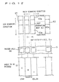
- the heat generating body 63 is 48 to 60 ⁇ m in the sub scanning direction parallel with the longitudinal direction of stripe of three primary colors printed on the sheet to be printed 51, and is 45 ⁇ m in the main scanning direction perpendicular to the sub scanning direction.
- the arranging pitch of the heat generating body 63 in the present embodiment substantially matches the pitch of the stripe of the color image forming sheet formed in the color area forming portion 53. That is, the heat generating bodies are disposed in the main scanning direction at a pitch of 62.5 ⁇ m.
- the stencil printing portion 62 has a printing drum 64 which is rotated around its own axis.
- An ink transmissive printing area is present in at least a part of the peripheral surface of the printing drum 64, and the perforated stencil printing sheet S is mounted on the peripheral surface of the printing drum 64 including the printing area.
- the printing drum 64 is interiorly provided with an ink supply means 65 for supplying ink to the inner peripheral surface of the printing drum 64.
- the printing drum 64 is driven in synchronism with the sheet feed belt 52 to apply printing to the sheet to be printed 51 while holding the sheet to be printed 51 between it and the sheet feed belt 52 to convey the same.
- black ink is used.
- the color image forming apparatus 50 in the present embodiment comprises a read means for reading a full color original image to be printed and a thermal head driving portion for processing image data read by the read means to produce a thermal head drive signal.
- the thermal head driving portion the stencil printing sheet S can be perforated so that adequate black printing is applied to each stripe of three colors formed on the sheet to be printed 51, and an original full color image can be reproduced by a color mixture of portions not covered by black.
- the present embodiment is configured so that perforated portions (master holes 66) of the perforated stencil printing sheet S mounted on the stencil printing portion 62 and stripes of various colors in the color area formed on the sheet to be printed 51 meet at the mutually corresponding position.
- the registration between the master holes 66 of the stencil printing sheet S on the printing drum 64 and the stripes of colors of the sheet to be printed 51 being fed from the color area forming portion 53 may be performed in the procedure similar to that of the previously described embodiment with reference to FIG. 5(b), for instance.
- a full color image (a color image) can be formed despite the fact that a single stencil printing sheet is used, a single printing drum is used, and a stencil printing operation is performed once.
- a black covering means is printed on a color image forming sheet prepared in advance to form a color image as desired.
- the stencil printing machine 20 shown in FIG. 6 is used. This using method is substantially similar to that of the previous embodiment described with reference to FIG. 6 except that black ink is used in place of white ink.
- the color image forming sheet used is the same as that shown in FIG. 1.
- Stripes whose phase substantially match the stripes of original colors in the color area of the color image forming sheet are formed on a transparent film with light reflecting color.
- a white stripe 71 is formed on a transparent sheet 70 as a transparent film.
- the stripe is placed upon an original 72, for which electronic copying is taken to form a second original 73 constituted by black stripes.
- the black stripes constituting the second original 73 substantially match in phase the stripes of the primary colors in the color area of the color image forming sheet.
- the stencil printing sheet S is placed upon the second original 73 composed of the black stripes, and a flash of light is irradiated from the side of the stencil printing sheet S to heat the black portions of the second original 73, and the stencil printing original S is heat-sensibly perforated.
- a stamp may be formed by using the stencil printing original S perforated by the method as in the present embodiment and pressed against the color image forming sheet to form a color image.
- the positional relation of the black stripes of the stamp is changed with respect to the stripes of the color area on the color image forming sheet every pressing.
- the coloration of the color image obtained changes delicately every time, and one can enjoy a colorful coloration and its change.
- a black covering means is provided on a color image forming sheet prepared in advance to reproduce a coloration as desired, can be performed substantially in the same manner as the method shown in FIGS. 7 and 8.
- a laser beam printer may be used to deposit a black toner on the color image forming sheet.
- a thermal transfer ribbon of black ink may be provided on a press for a word processor having a thermal head and a pattern formed on an image plane of the word processor is printed with black ink on the color image forming sheet to form an image of coloration.
- one surface of a transparent sheet with a black covering means printed thereon is used as a tacky surface, which is used as seal and pasted to the color image forming sheet to present various colorations. In this case, since a coloration delicately changes even if a position of the color image forming sheet to which the seal is pasted is slightly deviated, one can enjoy a color full coloration and its change.
- a discoloring layer or a chromophoric layer as a covering means so as to provide a pattern which substantially matches that of the whole surface thereof or the color area, and the layer is discolored or generated in color to conceal a part of the color area to present a color.
- the discoloring layers or chromophoric layers used include a heat sensitive chromophoric layer, a photochromism agent, a thermochromism agent, a piezochromism agent, a liquid crystal, etc.
- the photochromism agent changes in color by ultraviolet ray, and returns an original state at dark place. Accordingly, if the photochromism agent which discolors to black is printed on the YMC stripe so as to cover colors other than color as desired, only the portion of the photochromism agent becomes black when the ultraviolet ray is irradiated and only the color on the portion not covered with the photochromism agent is exposed. Observation is made as if a color image is levitated from a place where nothing is present. If the ultraviolet ray is not present, it returns to the original state, and the image disappears.
- the operation similar to that described above occurs by heat in case of the thermochromism agent and by pressure in case of the piezochromism agent. The similar operation is obtained by the liquid crystal due to heat or electric field.
- a heat sensitive chromophoric agent as a discoloring layer or a chromophoric layer will be desoribed.
- the heat sensitive chromophoric agent contains one component of a leuco dye and a developer or both components.
- the leuco dye which is a chromophoric agent component and an acidic material which is a developer component are fused or mixed together by applying heat, and as a result, the leuco dye changes from colorless to colored.
- leuco dye those which have been used for heat sensitive sheets can be used.
- fluoren, triphenylmethane, spiropyran, etc. are preferred. Specific examples of these include:
- the using ratio between the leuco dye and the developer is 1 weight part of leuco dye to 1 to 10 weight parts of developer, preferably in the range of 2 to 5 weight parts.
- Heat melting components can be contained in order to increase the chromophoric sensitivity.
- Compounds having a melting point of approximately 50 to 150° C, for example, such as fatty acid ester, fatty acid amido, wax and the like are preferred.
- Specific examples of these compounds include lauric amide; stearic amide, caproic amide, carnanba wax, montan wax, polyethylene wax, etc.
- the using amount of these heat melting components is 1 to 10 weight parts to 1 weight part of leuco dye, preferably in the range of 1 to 3 weight parts.
- the above-described heat sensitive agent is covered on the whole surface of the color image forming sheet in which a plurality of colors constitute a color area in a predetermined pattern (in the embodiment, stripes of YMC).
- a heat sensitive printer such as a word processor
- the thermal head of the heat sensitive printer blackens the heat sensitive agent to cover a part of the color area of the color image forming sheet. Therefore, a color image appears on the color image forming sheet.
- mounted on the word processor are a software for selecting what color of stripe of the color image forming sheet is selected according to the designated color, and a registration index or a registration sensor for registering the color image forming sheet with the position of the thermal head.
- the heat sensitive agent is printed not on the whole surface of the color image forming sheet but in a pattern of an image, similarly to the chromic agent, a color image can be formed on the color image forming sheet merely by applying heat.
- a color powder (such as a black toner) is deposited on the transparent tacky agent in an image pattern by sprinkling the color powder, and the image can be floated on the color image forming sheet.
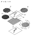
- a transparent sheet 80 is formed with a image (in the figure, letter of "ABC") in a black stripe 81.
- the image portions are constituted by the black stripes 81 which are different in width.
- the transparent sheets 80 are placed one upon another on the color area of the color image forming sheet 1 described with reference to FIG. 1.
- a ground color of the color image forming sheet 1 is observed from a transparent portion of the transparent sheet 80, and the image "ABC" is observed in three colors by the color mixture of primary colors not concealed by the black stripes 81, in the image portion of the transparent sheet 80.
- the black stripe 81 may be constituted with the phase (width and pitch) which substantially matches the stripe of the color image forming sheet 1, and the image may be formed on the transparent sheet 80 in black color.
- the stripe of CMY is formed on the transparent sheet 80 in transparent ink, and a black stripe is formed on a untransparent sheet, both of which are placed one upon another to observe it from the transparent sheet. Even this, the effect similar to that of FIG. 14 can be obtained.
- both the superposed sheets are not completely fixed but they can be moved relatively in at least a portion of a color image object.
- covering sheet 82 cannot be moved relative to the color image forming sheet 1.
- the coloration of the color image is changed by an extremely small relative movement of both the sheets 1 and 82. Therefore, one can enjoy a colorful color tone and its change, the visual aesthetical effect is extremely great, and this is also effective as an advertisement means.
- a covering means is placed upon at least a part of a color area composed of a plurality of colors arranged regularly, and a color is presented by a color mixture of colors not superposed to the covering means.
- various colors can be employed for colors constituting a color area, and a pattern constituted by the colors is not limited to a stripe but various patterns can be employed.
- various colors can be employed for colors of the covering means for covering the color area, and for the means for providing the covering means on the color area, various devices, appliances, materials, procedures and the like as illustrated in the embodiments can be applied.
- a covering means is placed upon at least a part of a color area composed of a plurality of colors arranged regularly, and a color is presented by a color mixture of colors not superposed to the covering means, there is an effect in that a convenience in color image printing such as that an image of color can be formed is materially improved.
Description
- The present invention relates to a color image forming method and the like in which images of colors can be obtained by simple means.
- In the field of printing, in order to obtain an image having a colorful color tone, there is used a method for performing a gathering printing using a plurality of inks of different color. For example, in a color printing, it has been general to employ a method of dividing at least three primary colors by plates, and sequentially performing a gathering printing to obtain a color image as desired.
- In the conventional procedure, it is necessary to perform plural times of processing and printing operation in order to obtain one color image, which is also cumbersome. This requires, in case of printing by manual operation, three times as long as that of the case where a monochromatic image is formed. In case of using a printing apparatus, the apparatus in scale of three times as large is required.
- The present invention seeks to provide a simple color image forming method and the like which can obtain a color image by a single operation similar to the monochromatic printing.
- The IBM Technical Disclosure Bulletin Vol. 25 No. 5 October 1982 discloses a method of additive colour printing in which, on a scale finer than the resolution of the eye, the surface to be colored is divided into dots or bars of the three primary additive colors, and in principle has each of these three sets of dots or bars coated uniformly with that primary colour. The ink may overlap or not quite meet at the boundaries of the color elements.
- The information and actual color choice are communicated to the picture by overprinting with a black pattern containing an aperture over each of the color elements, which aperture is of smaller or zero size when that additive color is supposed to be locally weak or absent, and which is of larger size when that additive primary color is present in large intensity in the desired hue and brightness. In this way, a white area would have large apertures in the black mask, allowing almost all of the tri-colored areas beneath to show through. Thus, the whites of the resulting picture could have a maximum brightness only about 30% that of the uncoated paper. The black, however, could be as black as the dark overprint ink.
- FR-A-389,297 discloses a method of obtaining colored effects by superimposing black lines on a color area formed by a series of parallel lines cycling through the colors red, green and blue.
- US-A-4,458,175 discloses a color printing system which can be effected using only a single impression of black ink if the image is coordinated to register on a sheet pre-printed with a non-imaged viewing screen Such uses for printing including newspapers and "quick print" type reproduction.
- With respect to printing, one or more 'color blocks' (viewing screens) can be pre-printed on the paper at the mill or by a converter. The entire stock is then warehoused for later use. At use, the pre-printed paper is fed into a conventional black impression press wherein the format is printed as conventionally done. Where a color picture is desired, such as on the front page of a newspaper, the color-coded black image of the desired picture is coordinated to register with the Mosaic Screen 'color block' pre-printed in that area, and a color picture results. Printing presses with photoelectric registration require no capital modification to utilize this color system. Four-color printing presses can form the color screen on three of the units and image with the black plate; changing the black plate then changes the color image.
- DE-A-43 39 216 describes one possible embodiment of recording carrier for coloured representations in which three colours red, green and blue are applied to a carrier through a coloured layer, in a regularly ordered mosaic. Applied over this coloured layer is a thermosensitive layer which, after prior thermal treatment, may be in a transparent, opaque or intermediate state. If necessary, a further transparent coating may be disposed over the
thermosensitive layer 3 and protect the thermosensitive layer from mechanical stress. - This suggested recording carrier is intended to be used as described hereinafter. In the basic state of the recording carrier, the thermosensitive layer is entirely in its opaque state, so that the sheet appears white. If it is required to generate a black or grey image in front of a white background, then in the areas which are to appear black or grey, the thermosensitive areas situated over all the mosaic dots are, by thermal treatment, completely or partially converted to the transparent state. To produce a coloured image, the thermosensitive areas situated over the corresponding coloured mosaic dots are entirely or partially switched to the transparent condition. In this way, any desired colours can be produced by a corresponding combination of the three basic colours.
- US-A-3,329,590 discloses a method for making a colored reproduction of a colored image which comprises projecting a colored light image onto a receptor comprising a relatively non-conductive backing, a metal layer overlying and affixed to said backing, and a photoconductive layer bonded to said metal layer to form the image receptive area comprising an admixture of a photoconductor and an insulating organic resinous binder, said photoconductive image receptive area being laterally divided into a pattern or mosaic of three different visually subtractive color forming areas, said three differentially subtractive colored areas separately containing at least one cyan forming coupler, at least one magenta forming coupler and at least one yellow forming coupler, and in addition separately containing at least one red-light sensitizing dye in said cyan forming area, at least one green-light sensitizing dye in the magenta color forming area, and at least one blue-light sensitizing dye in the yellow forming area, to form a differentially conductive pattern corresponding to said light image, subjecting said receptor containing the differentially conductive pattern to electrolysis in contact with an aqueous electrolytic solution containing a white pigment dispersed therein and a resin capable of depositing on the conductive areas of said receptor whereby the white pigment is affixed to the conductive areas of said receptor masking the color thereunder, and subsequently chemically developing the couplers in the non-masked color forming areas.
- The present invention is as claimed in the independent claims with optional features recited in the dependent claims.
- Embodiments of the present invention will now be described with reference to the accompanying drawings, in which:
- FIG. 1 is a perspective view showing an image forming sheet according to one embodiment and a partly enlarged view thereof;
- FIG. 2 is a perspective view showing an image forming sheet according to one embodiment having a covering means printed thereon and a partly enlarged view thereof;
- FIG. 3 is a perspective view showing an image forming sheet according to one embodiment having a covering means printed thereon and a partly enlarged view thereof;
- FIG. 4 is a perspective view showing a covering sheet having a covering means of white stripes, a color image forming sheet and a color image object obtained by placing both the sheets placed upon one another and a partly enlarged view of the covering sheet and the color image forming sheet;
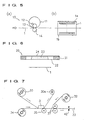
- FIG. 5 is a view showing a schematic construction of a color image forming apparatus making use of a rotary stencil press and the conveying mode of a color image forming sheet in the apparatus;
- FIG. 6 is a schematic construction view of a color image forming apparatus making use of a pressing stencil press;
- FIG. 7 is a schematic construction view of a color image forming apparatus using a ribbon-like color image forming sheet, a white transfer ribbon and a thermal head;
- FIG. 8 is an enlarged sectional view of a color image object formed by the apparatus shown in FIG. 7;
- FIG. 9 is a perspective view showing another embodiment of the color image forming apparatus;
- FIG. 10 is an enlarged perspective view of a web printing section of the color image forming apparatus shown in FIG. 9;
- FIG. 11 is a sectional view showing the construction of a printing roller in the web printing section of the color image forming apparatus shown in FIG. 9;
- FIG. 12 is a view showing the relationship between a heat generating body and a master hole in the color image forming apparatus shown in FIG. 9;
- FIG. 13 is a view for explaining the procedure for forming a covering means comprising a black stripe using an original image; and
- FIG. 14 is a perspective view showing a covering sheet having a covering means of black stripe, a color image forming sheet and a color image object obtained by placing both the sheets upon one another and a partly enlarged view of the covering sheet and the color image forming sheet.
-
- The present invention relates to a color image object provided with suitable colors obtained by a simple operation, a method for forming the color image object and an apparatus for forming the color image object, as defined in the independent claims. FIG. 1 shows a color
image forming sheet 1 used in one embodiment of the present invention. The colorimage forming sheet 1 has a color area comprising a plurality of colors arranged regularly provided on a sheet-like base such as paper. The color area of the colorimage forming sheet 1 according to the present embodiment has inks of three primary colors, cyan C, magenta M and yellow Y printed on a sheet-like base such as paper in a predetermined form. - In the present embodiment, as shown in an enlarged view of FIG. 1, inks of various colors are printed in a predetermined order alternately without clearance so as to have stripes (webs or stripes) having a predetermined width. Accordingly, the color
image forming sheet 1 can be observed as different colors as a whole by a color mixture of various colors. The whole color depends on the reflecting density of inks of various color, material of print sheet which is a body to be printed, and the like. For example, in case of wood free paper, the color is relatively dark brown at the reflecting density of 1.22, is relatively light brown at the reflecting density of 0.95, is light yellow or creamy yellow at the reflecting density of 0.54, and is light reddish white at the reflecting density of 0.38. If the balance of the reflecting density of inks of various colors to be printed, material of print sheet which is a body to be printed, and the like are changed, an image can be seen in black or grey. - In the present embodiment, the print width of webs of various colors can be freely set in the range of 0.05 mm to 0.22 mm in consideration of the visual effect. Accordingly, the stripes of various colors are repeated at a pitch of 0.15 to 0.66 mm. If the stripe width is set to approximately 0.1 mm or less, they exceed the resolving power of the naked eye and, therefore, the fact that the color area on the color
image forming sheet 1 is composed of three colors cannot be seen. As a result, the recognition of colors of a color mixture is naturally affected. If the stripe width is set to 0.22 mm or more, the color mixture is hard to obtain. This supposes the case of a color image object designed to be seen from a very close distance such as a card. However, in the case of a color image object to be seen from a relatively distant location, such as a poster, the stripe width of the various colors constituting a color area of the color image forming sheet may be large. - The aforementioned reflecting density is a value representative of a degree in which, when in reflection, a substance absorbs light. That is, let Io be the intensity of incident light and I be the intensity of reflection light, the reflecting density D is log10(Io/I). A densitometer for measuring the reflecting density is a reflecting densitometer RD-920(S) manufactured by Sakata Inks Co., Ltd., and the measuring range thereof is 0 to 2.50, and the colorimetric density is 0 to 2.50.
- If printing is made with a covering means placed upon a part of the color
image forming sheet 1, inks of a portion left without being covered are mixed and a constant color is presented. In the present embodiment, as the covering means, a white ink W was used. For example, as shown in FIG. 2, if only a portion of yellow Y of the colorimage forming sheet 1 is concealed in a web-like manner by white ink W, the colorimage forming sheet 1 is seen in blue (or purple) as a whole by the color mixture of the remaining cyan C and magenta M. - Further, as shown in FIG. 3, if the white ink W is printed in a web-like manner on a part of yellow Y and the whole cyan C of the color
image forming sheet 1, the colorimage forming sheet 1 is seen in red as a whole by the color mixture of the remaining part of yellow Y and magenta M. - FIGS. 2 and 3 illustrate that white ink W is printed in a web-like manner on the color
image forming sheet 1 corresponding to a stripe pattern for the colorimage forming sheet 1 to obtain a suitable color. Accordingly, it is possible to obtain colors other than those illustrated, and the colorimage forming sheet 1 presents a suitable color. Alternatively, a printing pattern of white ink W can be changed so that colors appearing every area within the colorimage forming sheet 1. For example, a full color image can be presented within the colorimage forming sheet 1. - FIG. 4 shows an example in which a single color
image forming sheet 1 is covered with white to present a color image comprising a plurality of colors. In this case, a white covering means such as white ink may be provided in a predetermined pattern on the colorimage forming sheet 1 by suitable means such as printing or transfer, etc. In this example, however, a predetermined image pattern comprising a white web-like portion and a transparent portion is formed on a covering sheet 2 which is a transparent sheet on which a white covering means is provided, which pattern is placed upon the colorimage forming sheet 1. - The covering sheet 2 shown in FIG. 4 has a transparent sheet covered with a white covering means. A portion formed with a image (in one example show, letters ABC) comprises a
white web portion 3 and atransparent portion 4, and other portions are a whitesolid portion 5. - As shown in an enlarged view in FIG. 4, in the present embodiment, a
white web portion 3 and atransparent portion 4 for constituting images of A, B and C are different in their width, spacing and the like from one another. - When the covering sheet 2 is placed upon the
image forming sheet 1 shown in FIG. 1, acolor image object 6 is obtained in which images A, B and C different in color from one another are disposed in a white ground. In the present embodiment, the colors of the images A, B and C are not specified, it is noted of course that suitable colors can be presented depending on the width of thewhite web portion 3 and the spacing. - Incidentally, it is noted in the example shown in FIG. 4 that the whole surface of the transparent sheet is covered in advance with the white covering means and the portion of the covering means corresponding to the image portion may be removed in a stripe fashion by a pattern by which a color is obtained, or a white solid portion and an image may be directly formed on the transparent sheet by the white covering means. It is further noted that a white stripe-like covering means is provided on only a portion corresponding to an image of a transparent sheet and nothing is provided on other portions which are left transparent. In this case, an image of suitable color appears in a ground color (a color being presented by the color mixture of three colors of CMY) of the color
image forming sheet 1. - Next, a color image forming apparatus will be described in which a part of the color
image forming sheet 1 is covered with a covering means having a predetermined pattern and an image of colors is presented by a color mixture of exposed primary colors. As the forming means of the covering means as described, there can be employed a method for printing white ink on a color image forming sheet, as in the example described by reference to FIGS. 2 and 3. - More specifically, rotary
stencil printing machine 10 as shown in FIG. 5(a) can be used. A stencil drum 11 having an ink transmissive peripheral wall is rotated about its own axis by drive means not shown. Within the stencil drum 11 are provided adoctor roller 12 and asqueegee roller 13 which constitute a part of ink supply means so that white ink as a covering means can squeegee on the inner peripheral surface of the stencil drum 11 in synchronism with the drive of the stencil drum 11. - A perforated stencil sheet is wound around the outer peripheral surface of the stencil drum 11. A stripe-like pattern of white ink to be printed on the color
image forming sheet 1 is perforated on the stencil sheet. It is of course the case that a web-like pattern formed on the stencil sheet corresponds to a stripe-like pattern of three colors formed on the colorimage forming sheet 1 so that a color appears on the colorimage forming sheet 1 after printing. The stencil sheet is wound around the stencil drum 11 so that the longitudinal direction of a stripe-like pattern formed on the stencil sheet coincides with the moving direction of the peripheral surface of the stencil drum 11. - Below the stencil drum 11 is provided a
press roller 14 as a pressing member in contact with or close to the stencil drum 11. The colorimage forming sheet 1 as a body to be printed which will be a color image object after printing is fed between the stencil drum 11 and thepress roller 14. As shown in FIG. 5(b), the colorimage forming sheet 1 is fed so that the longitudinal direction of a stripe-like pattern coincides with the feeding direction by the stencil drum and the press roller. - If in the rotary
stencil printing machine 10 having the above-described construction, white ink is printed in a predetermined stripe pattern from the stencil sheet of the stencil drum 11 on the colorimage forming sheet 1 supplied between the stencil drum 11 and thepress roller 14, an image of color is formed on the colorimage forming sheet 1. - In the printing operation using the
rotary press 10, the registration between the stencil sheet and the colorimage forming sheet 1 with respect to the width direction perpendicular to the conveying direction of the colorimage forming sheet 1 is important. When the relative positional relation therebetween is changed, the colors appearing are different. In view of this, the positions of webs of three primary colors are detected by a sensor at twocorners image forming sheet 1 to be conveyed, as shown in FIG. 5(b), so that the position in the width direction of the colorimage forming sheet 1 can be precisely managed, and a desired color can be realized faithfully. - As another method for printing white ink on the color
image forming sheet 1, astencil printing machine 20 as shown in FIG. 6 can be also used. Aperforated stencil sheet 22 is provided on the lower surface of a frame 21. A stripe-like pattern of white ink to be printed on the colorimage forming sheet 1 is perforated on thestencil sheet 22. Of course, the stripe-like pattern formed on thestencil sheet 22 corresponds to a stripe-like pattern of three primary colors formed on the colorimage forming sheet 1 and after printing, an image of color appears on the colorimage forming sheet 1. -
White ink 23 is placed on thestencil sheet 22, and acover 24 is provided on the upper surface of the frame 21 to cover thewhite ink 23. Thepressing press 20 is located at and placed on the colorimage forming sheet 1, and when pressing at a predetermined pressure, thewhite ink 23 is printed on the colorimage forming sheet 1 via thestencil sheet 22 in a predetermined stripe pattern, and as a result, an image of color is formed on the colorimage forming sheet 1. For locating the colorimage forming sheet 1 and thestencil sheet 22 in thepressing press 20 having the present construction, means similar to the locating of the rotarystencil printing machine 10 can be applied. - Next, as means for covering a part of a pattern of the color image forming sheet to present a color, there can be employed a procedure for providing a covering means on the color image forming sheet by a method other than the stencil printing.
- FIG. 7 shows an apparatus in which a
white transfer ribbon 30 and athermal head 31 are used to form a white stripe having a predetermined pattern on a roll-like colorimage forming sheet 32 to obtain acolor image object 33 of color. The roll-like transfer ribbon 30 and a roll-liketransparent film 34 are placed upon one another and are conveyed while being held by thethermal head 31 as transfer means and aplaten roller 35. - The
thermal head 31 applied with a drive signal transferswhite ink 36 of a transfer ribbon to thetransparent film 34. A pattern of thewhite ink 36 transferred to thetransparent film 34 corresponds to a stripe-like pattern of three primary colors formed on the colorimage forming sheet 32 described later, and after printing, a color appears on the colorimage forming sheet 32. - As shown in FIG. 7, a
transfer ribbon 30a after transfer is wound after being moved out of thethermal head 31. Thetransparent film 34 having thewhite ink 36 transferred thereto is fed into apressing feed roller 37. The roll-like colorimage forming sheet 32 is also fed into thepressing feed roller 37, and thetransparent film 34 and the colorimage forming sheet 32 are integrated. - As shown in FIG. 8, the color
image forming sheet 32 has asheet portion 38 formed on the front surface side with a stripe-like portion of three primary colors, atacky layer 39 provided on the front surface side of thesheet portion 38, and a strippingsheet 41 provided on the rear surface side of thesheet portion 38 through atacky layer 40. The construction of the stripe-like portion of three primary colors is similar to that described with reference to FIG. 1. - As shown in FIG. 8, the side of the
transparent film 34 to which thewhite ink 36 is transferred is pasted to thetacky layer 39 on the front surface side of the colorimage forming sheet 32 so that both are integrated. As observed from the side of thetransparent film 34, thewhite ink 36 having a predetermined pattern is placed upon a part of the pattern of three primary colors of the colorimage forming sheet 32. Accordingly, the colorimage forming sheet 32 will be acolor image object 33 having a color and image by the color mixture of primary colors not covered with thewhite ink 36. - The
color image object 33 discharged from thepressing feed roller 37 is cut into a length by acutter 42 and can be pasted to a suitable object by stripping the strippingsheet 41. - Both the stripe-like pattern of the
white ink 36 and the stripe-like pattern of primary colors in the present apparatus are parallel with the conveying direction. It is to be noted that in the registration therebetween, the axial position of the roll-like colorimage forming sheet 32 may be adjusted. - As other color image forming apparatuses, an apparatus can be used in which a laser beam printer is used to print a white toner on the color image forming sheet. Alternatively, a heat transfer ribbon of white ink is provided on a press for a word processor having a thermal head, and a pattern formed on an image plane of the word processor is printed on the color image forming sheet with white ink to form an image of color as mentioned above.
- Since in the above-described embodiment, the stripe-like pattern of primary colors in the color
image forming sheets - In the above-described embodiment, the case has been illustrated in which a part of a pattern of three primary colors, cyan, magenta and yellow is covered by the covering means to cause a color to present. This is one example of a subtractive color mixture for observing printed matter by a reflecting light.
- In the above-described embodiments, three primary colors having been used for the color image forming sheet, it is to be noted that in the present invention, three primary colors need not be necessarily used as colors constituting a color area. For example, even if two colors out of three primary colors are used, coloration comprising three colors or more can be presented. Further, the color area formed on the color image forming sheet need not be necessarily constituted by the primary colors but other colorations can be employed. For example, there can be suitably employed, in consideration of visual effect, various intermediate color other than primary colors, metal luster colors including gold color and silver color, pearl luster color, fluorescent color, colorations by ink including metal powder, and the like. For example, if the fluorescent color is employed, the whole image can be seen sharply and brightly.
- In the above-described embodiments, the covering means provided on the color image forming sheet by printing or the covering means provided on the covering sheet was white or black, the covering means according to the present invention need not be necessarily white or black. Various colorations as mentioned above used in the color area of the color image forming sheet can be employed as coloration of the covering means while taking the visual effect by a combination of colors used in the color image forming sheet into consideration. It is to be noted that in the case where the covering means is placed upon the color image forming sheet, the coloration having a predetermined pattern constituting the color image forming sheet is surrounded by a black pattern in a finely visual mode. Therefore, the contour of the image appearing on the color image forming sheet becomes clearer.
- In the above-described embodiments, the covering means is provided on the color image forming sheet having the color area to obtain a color, it is noted that the color area need not necessarily be provided on the sheet-like object. For example, a color area similar to the color image forming sheet is formed on the surface of an article having a three-dimensional configuration, and the covering means is provided thereon to present a color on the surface of the article.
- In the above-described embodiments, a stripe pattern is employed as a pattern of colors constituting a color area on the color image forming sheet, and the covering means having a stripe pattern is placed thereupon to form an image of a color. In this case, for the locating of the pattern of colors to the covering means, a high precision is not required at least in the longitudinal direction of the stripe, and if the locating is made in the direction perpendicular to the stripe, a color can be realized precisely.
- Next, another embodiment of the color image forming apparatus will be described with reference to FIG. 9 to 12. This color
image forming apparatus 50 can print a color area of a stripe pattern of three primary colors, cyan, magenta and yellow on a sheet to be printed 51 which is a body to be printed to form a color image forming sheet, and continuously thereto can print black ink as covering means on the color image forming sheet so that the phase thereof substantially matches the stripe to present an image of color on the color image forming sheet. - The color
image forming apparatus 50 has asheet feed belt 52 as the conveying means for conveying the sheet to be printed 51. Above thesheet feed belt 51 is provided a colorarea forming portion 53 at the first half position in the conveying direction. The colorarea forming portion 53 has threeweb printing portions 4, each of theweb printing portions 54 continuously printing a stripe pattern of three primary colors, cyan
C, magenta M and yellow Y on the sheet to be printed 51 to form a color image forming sheet. - As shown in FIG. 10, the
web printing portions 54 each have aprinting roller 55 and anink pad 56 for supplying ink to theprinting roller 55. Ink of various colors is supplied to each of theink pads 56 by an ink supply means not shown. Theprinting roller 55 has arotational shaft 55a perpendicular to the conveying direction of the sheet to be printed 51. Theprinting roller 55 is rotated in synchronism with the drive of thesheet feed belt 51 to apply printing to the sheet to be printed 51 while holding the sheet to be printed 51 between it and thesheet feed belt 51. Theprinting roller 55 is formed in its peripheral surface with a plumber ofconvex portions 57 having a predetermined width parallel with the conveying direction of the sheet to be printed 51 with agroove 58 having a predetermined width put therebetween. As shown in FIG. 11, in the present embodiment, the width of theconvex portion 57 is 62.5 µm and the width of thegroove 58 is 125 µm. Theconvex portions 57 of theprinting rollers 55 of threeweb printing portions 54 are deviated by one (1) pitch (62.5 µm) in the direction of therotational shaft 55a of eachprinting roller 55, and the stripes of cyan, magenta and yellow can be printed continuously without clearance on the single sheet to be printed 51. According to the kind of ink, the pitch of theconvex portions 57 may be remained unchanged with the width of theconvex portion 57 being 60 µm, and a clearance may be provided between the stripes formed on the sheet to be printed. The clearance on which stripe is not printed serves as a blur preventing portion for the adjacent stripes. In this case, further, there can be also obtained the operation for making the whole sheet to be printed 51 brighter. - As shown in FIG. 9, above the
sheet feed belt 51 is provided a coveringarea forming section 60 at a the latter half position in the conveying direction. The coveringarea forming section 60 has athermal head 61 for heat-sensitively perforating a stencil printing sheet S for perforation and astencil printing portion 62 to which the perforated stencil printing sheet S is attached and which is driven. - As shown in FIG. 12, the
thermal head 61 has a number ofheat generating bodies 63 arranged in a predetermined pitch in the main scanning direction. The heat generating bodies each are provided on anelectrode 63a. In the present embodiment, theheat generating body 63 is 48 to 60 µm in the sub scanning direction parallel with the longitudinal direction of stripe of three primary colors printed on the sheet to be printed 51, and is 45 µm in the main scanning direction perpendicular to the sub scanning direction. Further, the arranging pitch of theheat generating body 63 in the present embodiment substantially matches the pitch of the stripe of the color image forming sheet formed in the colorarea forming portion 53. That is, the heat generating bodies are disposed in the main scanning direction at a pitch of 62.5 µm. - The
stencil printing portion 62 has aprinting drum 64 which is rotated around its own axis. An ink transmissive printing area is present in at least a part of the peripheral surface of theprinting drum 64, and the perforated stencil printing sheet S is mounted on the peripheral surface of theprinting drum 64 including the printing area. Theprinting drum 64 is interiorly provided with an ink supply means 65 for supplying ink to the inner peripheral surface of theprinting drum 64. Theprinting drum 64 is driven in synchronism with thesheet feed belt 52 to apply printing to the sheet to be printed 51 while holding the sheet to be printed 51 between it and thesheet feed belt 52 to convey the same. In the present embodiment, black ink is used. - Although not shown, the color
image forming apparatus 50 in the present embodiment comprises a read means for reading a full color original image to be printed and a thermal head driving portion for processing image data read by the read means to produce a thermal head drive signal. According to the thermal head driving portion, the stencil printing sheet S can be perforated so that adequate black printing is applied to each stripe of three colors formed on the sheet to be printed 51, and an original full color image can be reproduced by a color mixture of portions not covered by black. - As shown in FIG. 12, in the present embodiment, it is configured so that perforated portions (master holes 66) of the perforated stencil printing sheet S mounted on the
stencil printing portion 62 and stripes of various colors in the color area formed on the sheet to be printed 51 meet at the mutually corresponding position. The registration between the master holes 66 of the stencil printing sheet S on theprinting drum 64 and the stripes of colors of the sheet to be printed 51 being fed from the colorarea forming portion 53 may be performed in the procedure similar to that of the previously described embodiment with reference to FIG. 5(b), for instance. - According to the color
image forming apparatus 50 of the present embodiment, a full color image (a color image) can be formed despite the fact that a single stencil printing sheet is used, a single printing drum is used, and a stencil printing operation is performed once. - Next, an embodiment will be described in which a black covering means is printed on a color image forming sheet prepared in advance to form a color image as desired. In this embodiment, the
stencil printing machine 20 shown in FIG. 6 is used. This using method is substantially similar to that of the previous embodiment described with reference to FIG. 6 except that black ink is used in place of white ink. The color image forming sheet used is the same as that shown in FIG. 1. - The perforation method for the stencil printing sheet S used here will be described with reference to FIG. 13. Stripes whose phase substantially match the stripes of original colors in the color area of the color image forming sheet are formed on a transparent film with light reflecting color. In the present embodiment, a
white stripe 71 is formed on atransparent sheet 70 as a transparent film. The stripe is placed upon an original 72, for which electronic copying is taken to form a second original 73 constituted by black stripes. The black stripes constituting the second original 73 substantially match in phase the stripes of the primary colors in the color area of the color image forming sheet. The stencil printing sheet S is placed upon the second original 73 composed of the black stripes, and a flash of light is irradiated from the side of the stencil printing sheet S to heat the black portions of the second original 73, and the stencil printing original S is heat-sensibly perforated. It is to be noted that a stamp may be formed by using the stencil printing original S perforated by the method as in the present embodiment and pressed against the color image forming sheet to form a color image. In this case, the positional relation of the black stripes of the stamp is changed with respect to the stripes of the color area on the color image forming sheet every pressing. Thus, the coloration of the color image obtained changes delicately every time, and one can enjoy a colorful coloration and its change. - The method, in which a black covering means is provided on a color image forming sheet prepared in advance to reproduce a coloration as desired, can be performed substantially in the same manner as the method shown in FIGS. 7 and 8. Further, a laser beam printer may be used to deposit a black toner on the color image forming sheet. Alternatively, a thermal transfer ribbon of black ink may be provided on a press for a word processor having a thermal head and a pattern formed on an image plane of the word processor is printed with black ink on the color image forming sheet to form an image of coloration. Further, one surface of a transparent sheet with a black covering means printed thereon is used as a tacky surface, which is used as seal and pasted to the color image forming sheet to present various colorations. In this case, since a coloration delicately changes even if a position of the color image forming sheet to which the seal is pasted is slightly deviated, one can enjoy a color full coloration and its change.
- Next, an embodiment will be described in which on the side of a color area of a color image forming sheet is provided a discoloring layer or a chromophoric layer as a covering means so as to provide a pattern which substantially matches that of the whole surface thereof or the color area, and the layer is discolored or generated in color to conceal a part of the color area to present a color.
- The discoloring layers or chromophoric layers used include a heat sensitive chromophoric layer, a photochromism agent, a thermochromism agent, a piezochromism agent, a liquid crystal, etc.
- The photochromism agent changes in color by ultraviolet ray, and returns an original state at dark place. Accordingly, if the photochromism agent which discolors to black is printed on the YMC stripe so as to cover colors other than color as desired, only the portion of the photochromism agent becomes black when the ultraviolet ray is irradiated and only the color on the portion not covered with the photochromism agent is exposed. Observation is made as if a color image is levitated from a place where nothing is present. If the ultraviolet ray is not present, it returns to the original state, and the image disappears. The operation similar to that described above occurs by heat in case of the thermochromism agent and by pressure in case of the piezochromism agent. The similar operation is obtained by the liquid crystal due to heat or electric field.
- A heat sensitive chromophoric agent as a discoloring layer or a chromophoric layer will be desoribed. The heat sensitive chromophoric agent contains one component of a leuco dye and a developer or both components. The leuco dye which is a chromophoric agent component and an acidic material which is a developer component are fused or mixed together by applying heat, and as a result, the leuco dye changes from colorless to colored.
- As the leuco dye, those which have been used for heat sensitive sheets can be used. For example, fluoren, triphenylmethane, spiropyran, etc. are preferred. Specific examples of these include:
- 3-cyclohexylamino-6-chlorofluoran
- 3-dimethylamino-5,7-dimethylfluoran
- 3-dimethylamino-7-chlorofluoran
- 3-dimethylamino-7-methylfluoran
- 3-dimethylamino-7,8-benzfluoran
- 3-dimethylamino-6-methyl-7-chlorofluoran
- 3-diethylamino-7-(o-chloroanilino)fluoran
- 3-dibutylamino-7-(o-chloroanilino)fluoran
- 3-(N-methyl-N-amyl)amino-6-methyl-7-anilinofluoran
- 3-(N-methyl-N-cyclohexyl)amino-6-methyl-7-anilinofluoran
- 3-diethylamino-6-methyl-7-anilinofluoran
- 3-morpholino-7-(N-propyl-trifluoromethylanilino)fluoran
- 3-pyridino7-trifluoromethylaniolinofluoroan
- 3-pyridino-7-(di-p-chlorophenyl)methylaminofluoran
- 3-diethylamino-5-chloro-7-(α-phenylethylamino)fluoran
- 3-diethylamino-5-methyl-7-(α-phenylethylamino)fluoran
- 3-diethylamino-7-piperidinofluoran
- 3,3-bis(p-dimethylaminophenyl)-phthalide
- 3,3-bis(p-dibutylaminophenyl)-phtalide
- 3,3-bis(p-dimethylaminophenyl)-6-dimethylaminophthalide
- 3,3-bis(p-dithylaminophenyl)-6-diethylaminophthalide
- 3,3-bis(p-dimethylaminophenyl)-6-chloroaminophthalide As the developer, various acidic materials which react with the leuco dye when in heating to color-generate the leuco dye can be used. For example, phenol materials, organic or inorganic acidic materials are preferred. Specific examples of these include:
- Salicylic acid, 3-isopropylsalicylie acid,
- 3-cyclohexylsalicylic acid,
- 4,4'-isopropylidendiphenol(bisphenol),
- 4,4'-isopropylidenbis(2-chlorophenyl),
- 4,4'-isopropylidenbis (2,6-dibromophenol),
- 4,4'-isopropylidenbis(2-methylphenol),4,4'-cyclohexylidenbi sphenol, 4,4'-cyclohexylidenbis(2-methylphenol),
- 4-phenylphenol, α-naphthol, α-naphthol,
- 3,5-xylenol, thymol, 4-hydroxyacetophenone, catechol, resorcinol, pyrogallol,
- 2,2'-methylenebis(4-chlorophenol), 2,2'-dihydroxydiphenyl,
- p-chlorobenzyl-p-hydroxybenzoic acid. p-methylbenzyl-p-hydroxybenzoic acid benzoic acid 1-hydroxy-2-naphthoic acid, 4-hydroxydiphenylsulfone,
- bis(4-hydroxyphenyl)sulfide, 2-hydroxy-p-toluic acid,
- tartaric acid, oxalic acid, maleic acid, citric acid,
- succinic acid, boric acid, clay, activated clay, etc.
-
- The using ratio between the leuco dye and the developer is 1 weight part of leuco dye to 1 to 10 weight parts of developer, preferably in the range of 2 to 5 weight parts.
- Heat melting components can be contained in order to increase the chromophoric sensitivity. Compounds having a melting point of approximately 50 to 150° C, for example, such as fatty acid ester, fatty acid amido, wax and the like are preferred. Specific examples of these compounds include lauric amide; stearic amide, caproic amide, carnanba wax, montan wax, polyethylene wax, etc. The using amount of these heat melting components is 1 to 10 weight parts to 1 weight part of leuco dye, preferably in the range of 1 to 3 weight parts.
- The above-described heat sensitive agent is covered on the whole surface of the color image forming sheet in which a plurality of colors constitute a color area in a predetermined pattern (in the embodiment, stripes of YMC). When the color image forming sheet is printed by a heat sensitive printer such as a word processor, the thermal head of the heat sensitive printer blackens the heat sensitive agent to cover a part of the color area of the color image forming sheet. Therefore, a color image appears on the color image forming sheet.
- In this case, mounted on the word processor are a software for selecting what color of stripe of the color image forming sheet is selected according to the designated color, and a registration index or a registration sensor for registering the color image forming sheet with the position of the thermal head.
- Further, if the heat sensitive agent is printed not on the whole surface of the color image forming sheet but in a pattern of an image, similarly to the chromic agent, a color image can be formed on the color image forming sheet merely by applying heat.
- Further, if an image is printed on the color image forming sheet by a transparent tacky agent, a color powder (such as a black toner) is deposited on the transparent tacky agent in an image pattern by sprinkling the color powder, and the image can be floated on the color image forming sheet.
- Next, an embodiment will be described in which the color image forming sheet and the covering sheet in which black covering means is printed on the transparent sheet, shown in FIG. 1, are used, both of which are placed one upon another to form a color image. As shown in FIG. 14, a
transparent sheet 80 is formed with a image (in the figure, letter of "ABC") in ablack stripe 81. The image portions are constituted by theblack stripes 81 which are different in width. Thetransparent sheets 80 are placed one upon another on the color area of the colorimage forming sheet 1 described with reference to FIG. 1. A ground color of the colorimage forming sheet 1 is observed from a transparent portion of thetransparent sheet 80, and the image "ABC" is observed in three colors by the color mixture of primary colors not concealed by theblack stripes 81, in the image portion of thetransparent sheet 80. Theblack stripe 81 may be constituted with the phase (width and pitch) which substantially matches the stripe of the colorimage forming sheet 1, and the image may be formed on thetransparent sheet 80 in black color. - The stripe of CMY is formed on the
transparent sheet 80 in transparent ink, and a black stripe is formed on a untransparent sheet, both of which are placed one upon another to observe it from the transparent sheet. Even this, the effect similar to that of FIG. 14 can be obtained. - Next, in the embodiment in which the color
image forming sheet 1 shown in FIG. 1 and acovering sheet 82 in which a black stripe is printed on thetransparent sheet 80 are used, both of which are placed one upon another to form a image, both the superposed sheets are not completely fixed but they can be moved relatively in at least a portion of a color image object. For example, only one sides corresponding to both rectangular sheets are fixed to each other, and coveringsheet 82 cannot be moved relative to the colorimage forming sheet 1. In this way, the coloration of the color image is changed by an extremely small relative movement of both thesheets - According to the present invention, a covering means is placed upon at least a part of a color area composed of a plurality of colors arranged regularly, and a color is presented by a color mixture of colors not superposed to the covering means. As will be apparent from the above-described embodiments, various colors can be employed for colors constituting a color area, and a pattern constituted by the colors is not limited to a stripe but various patterns can be employed. Furthermore, various colors can be employed for colors of the covering means for covering the color area, and for the means for providing the covering means on the color area, various devices, appliances, materials, procedures and the like as illustrated in the embodiments can be applied.
- Since according to the present invention, a covering means is placed upon at least a part of a color area composed of a plurality of colors arranged regularly, and a color is presented by a color mixture of colors not superposed to the covering means, there is an effect in that a convenience in color image printing such as that an image of color can be formed is materially improved.
Claims (7)
- A color image forming method, comprising: placing a covering means upon a color area, said color area having a plurality of colors formed in stripes and being light reflective, said covering means being formed in stripes whose phase substantially matches with respect to the stripes of said color area and being formed in a pattern of a desired image; and presenting the image in a color by a subtractive color mixture of colors not covered by said covering means in said color area.
- A color image forming method according to claim 1, further comprising any of the following:in which case further optionally one of the following:a) wherein said color area is composed of three primary colors, cyan, magenta and yellow;b) wherein said color area is composed of at least two primary colors selected out of three primacy colors, cyan, magenta and yellow;c) wherein said color area includes colors other than three primary colors, cyan, magenta and yellow;d) wherein said covering means is formed on a light transmitting sheet, said light transmitting sheet being placed upon said color area;e) wherein a discoloring layer is provided on said color area, said discoloring layer being discolored to form said covering means;f) wherein said covering means is printed on said color area;
wherein said covering means is black;
wherein said covering means is white;
wherein each width of the stripe in said color area is smaller than the width to be resolved by the naked eye;
wherein a light transmitting film having stripes of a light reflective color whose phase substantially matches the stripes of a plurality of colors in said color area is placed upon an image of an original, which is used to form an image comprising black stripes whose phase substantially matches the stripes of a plurality of colors in said color area, and the covering means is formed using an image comprising said black stripes. - A color image forming apparatus in which a covering means is placed upon a color area, said color area having a plurality of colors formed in stripes and being light reflective, said covering means being formed in stripes whose phase substantially matches with respect to the stripes of said color area and being formed in a pattern of a desired image; and the image in a color is presented by a subtractive color mixture of colors not covered by said covering means in said color area.
- A color image forming apparatus according to claim 3, further comprising a conveying means for a body to be formed, a color area forming section for forming a color area composed of a plurality of colors regularly arranged on said body to be formed, and a covering area forming section for forming a covering area placed upon at least a part of the colors of said color area on said body to be formed, in which case optionally
wherein said color area forming section comprises a stripe printing section for forming said stripes of a plurality of colors by being arranged on said body to be formed in a predetermined order and pitch parallel with the conveying direction of said body to be formed, and said covering area forming section comprises a thermal head for perforating a stencil sheet by a plurality of heat generating bodies arranged in a predetermined pitch, and a stencil printing section driven with the stencil sheet perforated by said thermal head mounted; in which latter case optionally
wherein a pitch of the heat generating bodies of said thermal head substantially matches the stripes of various colors of said color area formed on said body to be formed, and the perforated portion of the processed stencil sheet mounted on said stencil printing section and the stripes of various color in said color area formed on said body to be formed correspond to each other; in which latter case optionally
wherein said plurality of colors in said color area are colors of cyan, magenta and yellow, and said covering area is black. - A color image object comprising a color image forming sheet and a covering means for covering said color image forming sheet, said color image forming sheet comprising a color area having a plurality of colours formed in stripes and being light reflective, said covering means being formed in stripes whose phase substantially matches with respect to the stripes of said color area, wherein a color is presented by a subtractive color mixture of colors not covered by said covering means in said color area.
- A color image object according to claim 5, wherein said covering means is formed in a pattern of a desired image and placed upon said color area of said color image forming sheet, and optionally said covering means is black.
- A color image object according to claim 5, wherein a covering sheet provided with said covering means for covering part of said color area of maid color image forming sheet is placed upon said color image forming sheet provided with said color area, said covering means is formed in a pattern of a desired image, said color image forming sheet and said covering sheet are placed upon one another so that they are relatively moved.
Applications Claiming Priority (9)
| Application Number | Priority Date | Filing Date | Title |
|---|---|---|---|
| JP117101/95 | 1995-05-16 | ||
| JP117102/95 | 1995-05-16 | ||
| JP11710295 | 1995-05-16 | ||
| JP11710395 | 1995-05-16 | ||
| JP11710295A JPH08310098A (en) | 1995-05-16 | 1995-05-16 | Color image forming device |
| JP7117101A JPH08310102A (en) | 1995-05-16 | 1995-05-16 | Formation of color image |
| JP11710395A JPH08310103A (en) | 1995-05-16 | 1995-05-16 | Color image forming sheet, covering sheet and color image |
| JP11710195 | 1995-05-16 | ||
| JP117103/95 | 1995-05-16 |
Publications (2)
| Publication Number | Publication Date |
|---|---|
| EP0743190A1 EP0743190A1 (en) | 1996-11-20 |
| EP0743190B1 true EP0743190B1 (en) | 2002-09-25 |
Family
ID=27313297
Family Applications (1)
| Application Number | Title | Priority Date | Filing Date |
|---|---|---|---|
| EP96303477A Expired - Lifetime EP0743190B1 (en) | 1995-05-16 | 1996-05-16 | Color image forming method, color forming apparatus and color image |
Country Status (3)
| Country | Link |
|---|---|
| US (1) | US6546128B1 (en) |
| EP (1) | EP0743190B1 (en) |
| DE (1) | DE69623849T2 (en) |
Families Citing this family (6)
| Publication number | Priority date | Publication date | Assignee | Title |
|---|---|---|---|---|
| JPH09150569A (en) * | 1995-11-29 | 1997-06-10 | Riso Kagaku Corp | Color image forming sheet |
| JP4414273B2 (en) * | 2004-05-13 | 2010-02-10 | 東芝テック株式会社 | Method for producing thermal recording medium |
| GB0614778D0 (en) * | 2006-07-25 | 2006-09-06 | Dymo Nv | Tape supply and tape cassette |
| FR3013256B1 (en) * | 2013-11-15 | 2016-01-15 | Oberthur Technologies | METHOD FOR VISUAL CUSTOMIZATION OF AN IDENTITY DOCUMENT HAVING A LATENT IMAGE |
| USD764151S1 (en) * | 2015-05-11 | 2016-08-23 | Eric J. Gewirz | Hat with lenticular panel |
| KR102443286B1 (en) * | 2017-03-09 | 2022-09-14 | 도판 인사츠 가부시키가이샤 | Display body, booklet, ID card, manufacturing method of a display body, and manufacturing apparatus of a display body |
Family Cites Families (12)
| Publication number | Priority date | Publication date | Assignee | Title |
|---|---|---|---|---|
| FR389297A (en) | 1907-05-04 | 1908-09-04 | Julius Rheinberg | Improvements to color printing |
| FR665029A (en) | 1928-02-13 | 1929-09-13 | Polychrome frame | |
| DE652579C (en) | 1935-10-15 | 1937-11-03 | Lord Investierungs Korporation | Device for the printing production of color line grids for color photographic purposes |
| US2270746A (en) | 1939-03-13 | 1942-01-20 | Charles W Wyckoff | Color photography |
| NL273964A (en) | 1961-04-07 | |||
| US3429702A (en) | 1963-06-19 | 1969-02-25 | Leslie Howard Lorber | Process of producing multicolor utilizing a single printing plate |
| US4458175A (en) * | 1977-04-13 | 1984-07-03 | Weekley Robert R | Mosaic additive reflectance color display screen |
| JPS60202446A (en) | 1984-03-27 | 1985-10-12 | Ricoh Co Ltd | Preparation of photosensitive body for one-shot color electrophotography |
| US4731313A (en) * | 1985-08-23 | 1988-03-15 | Konishiroku Photo Industry Co., Ltd. | Apparatus for forming color images and method of use thereof |
| US5545506A (en) * | 1992-01-28 | 1996-08-13 | Hoechst Celanese Corporation | Method of producing an image using a negative working, peel developable, single sheet color proofing system |
| DE4339216A1 (en) | 1993-11-18 | 1994-04-21 | Raoul Dr Nakhmanson | Thermosensitive imaging screen structure for colour displays - using red-green-blue colour matrix with optically active transparent and partially or completely opaque layers |
| JPH09150569A (en) * | 1995-11-29 | 1997-06-10 | Riso Kagaku Corp | Color image forming sheet |
-
1996
- 1996-05-09 US US08/644,006 patent/US6546128B1/en not_active Expired - Fee Related
- 1996-05-16 EP EP96303477A patent/EP0743190B1/en not_active Expired - Lifetime
- 1996-05-16 DE DE69623849T patent/DE69623849T2/en not_active Expired - Fee Related
Also Published As
| Publication number | Publication date |
|---|---|
| EP0743190A1 (en) | 1996-11-20 |
| DE69623849T2 (en) | 2003-01-23 |
| US6546128B1 (en) | 2003-04-08 |
| DE69623849D1 (en) | 2002-10-31 |
Similar Documents
| Publication | Publication Date | Title |
|---|---|---|
| EP0776766B1 (en) | Color image forming sheet | |
| US5396839A (en) | Apparatus and method for printing color images | |
| DE69133309T2 (en) | Thermal transfer method and device for this method | |
| CN101855092B (en) | Method of printing | |
| EP0743190B1 (en) | Color image forming method, color forming apparatus and color image | |
| US4457540A (en) | Multicolor printed product containing pearl luster pigment | |
| US5175139A (en) | Method of heat transfer printing and heat transfer sheet | |
| US5021112A (en) | Process of multicolor printing by laser | |
| JPH08310102A (en) | Formation of color image | |
| JPH08310103A (en) | Color image forming sheet, covering sheet and color image | |
| JPH08310098A (en) | Color image forming device | |
| US6471811B1 (en) | Ink color proofing | |
| JPH03138178A (en) | Ink cassette for thermal transfer printer | |
| JPS60208283A (en) | Thermal recording paper | |
| JPH07137349A (en) | Color image forming method, color image forming device, color image forming sheet, and color image | |
| US8440588B2 (en) | Creating background colors on thermal printing material | |
| JP3597931B2 (en) | Color image forming sheet and color image forming method | |
| JPS5935981A (en) | Image formation body | |
| JPS62208986A (en) | Laser multicolor recording method | |
| JP4157781B2 (en) | Thermal recording medium | |
| JP2005313508A (en) | Thermosensitive recording paper | |
| CN116133870A (en) | Multicolor thermoprinting printing system | |
| JPS5993353A (en) | Color printer mechanism | |
| JP5966311B2 (en) | Manufacturing method of copy forms | |
| JPH0220380A (en) | Preparation of no-carbon multicolor copying image and substrate for copying used for said method |
Legal Events
| Date | Code | Title | Description |
|---|---|---|---|
| PUAI | Public reference made under article 153(3) epc to a published international application that has entered the european phase |
Free format text: ORIGINAL CODE: 0009012 |
|
| 17P | Request for examination filed |
Effective date: 19960916 |
|
| AK | Designated contracting states |
Kind code of ref document: A1 Designated state(s): DE FR GB |
|
| 17Q | First examination report despatched |
Effective date: 19980810 |
|
| RTI1 | Title (correction) |
Free format text: COLOR IMAGE FORMING METHOD, COLOR FORMING APPARATUS AND COLOR IMAGE |
|
| GRAG | Despatch of communication of intention to grant |
Free format text: ORIGINAL CODE: EPIDOS AGRA |
|
| GRAG | Despatch of communication of intention to grant |
Free format text: ORIGINAL CODE: EPIDOS AGRA |
|
| GRAH | Despatch of communication of intention to grant a patent |
Free format text: ORIGINAL CODE: EPIDOS IGRA |
|
| GRAH | Despatch of communication of intention to grant a patent |
Free format text: ORIGINAL CODE: EPIDOS IGRA |
|
| GRAA | (expected) grant |
Free format text: ORIGINAL CODE: 0009210 |
|
| AK | Designated contracting states |
Kind code of ref document: B1 Designated state(s): DE FR GB |
|
| REG | Reference to a national code |
Ref country code: GB Ref legal event code: FG4D |
|
| REF | Corresponds to: |
Ref document number: 69623849 Country of ref document: DE Date of ref document: 20021031 |
|
| ET | Fr: translation filed | ||
| PLBE | No opposition filed within time limit |
Free format text: ORIGINAL CODE: 0009261 |
|
| STAA | Information on the status of an ep patent application or granted ep patent |
Free format text: STATUS: NO OPPOSITION FILED WITHIN TIME LIMIT |
|
| 26N | No opposition filed |
Effective date: 20030626 |
|
| PGFP | Annual fee paid to national office [announced via postgrant information from national office to epo] |
Ref country code: FR Payment date: 20090515 Year of fee payment: 14 Ref country code: DE Payment date: 20090514 Year of fee payment: 14 |
|
| PGFP | Annual fee paid to national office [announced via postgrant information from national office to epo] |
Ref country code: GB Payment date: 20090513 Year of fee payment: 14 |
|
| GBPC | Gb: european patent ceased through non-payment of renewal fee |
Effective date: 20100516 |
|
| REG | Reference to a national code |
Ref country code: FR Ref legal event code: ST Effective date: 20110131 |
|
| PG25 | Lapsed in a contracting state [announced via postgrant information from national office to epo] |
Ref country code: DE Free format text: LAPSE BECAUSE OF NON-PAYMENT OF DUE FEES Effective date: 20101201 |
|
| PG25 | Lapsed in a contracting state [announced via postgrant information from national office to epo] |
Ref country code: FR Free format text: LAPSE BECAUSE OF NON-PAYMENT OF DUE FEES Effective date: 20100531 |
|
| PG25 | Lapsed in a contracting state [announced via postgrant information from national office to epo] |
Ref country code: GB Free format text: LAPSE BECAUSE OF NON-PAYMENT OF DUE FEES Effective date: 20100516 |