EP0743180A2 - Unmachined die-cast aluminium end ring for a cylindrical screen - Google Patents
Unmachined die-cast aluminium end ring for a cylindrical screen Download PDFInfo
- Publication number
- EP0743180A2 EP0743180A2 EP96830264A EP96830264A EP0743180A2 EP 0743180 A2 EP0743180 A2 EP 0743180A2 EP 96830264 A EP96830264 A EP 96830264A EP 96830264 A EP96830264 A EP 96830264A EP 0743180 A2 EP0743180 A2 EP 0743180A2
- Authority
- EP
- European Patent Office
- Prior art keywords
- ring
- fabric printing
- ring nut
- die
- nuts
- Prior art date
- Legal status (The legal status is an assumption and is not a legal conclusion. Google has not performed a legal analysis and makes no representation as to the accuracy of the status listed.)
- Withdrawn
Links
- XAGFODPZIPBFFR-UHFFFAOYSA-N aluminium Chemical compound [Al] XAGFODPZIPBFFR-UHFFFAOYSA-N 0.000 title claims abstract description 9
- 239000004411 aluminium Substances 0.000 title claims abstract description 8
- 229910052782 aluminium Inorganic materials 0.000 title claims abstract description 8
- PXHVJJICTQNCMI-UHFFFAOYSA-N Nickel Chemical compound [Ni] PXHVJJICTQNCMI-UHFFFAOYSA-N 0.000 claims abstract description 8
- 238000004512 die casting Methods 0.000 claims abstract description 8
- 238000003754 machining Methods 0.000 claims abstract description 8
- 229910000838 Al alloy Inorganic materials 0.000 claims abstract description 6
- 239000000956 alloy Substances 0.000 claims abstract description 4
- 229910052759 nickel Inorganic materials 0.000 claims abstract description 4
- 230000002093 peripheral effect Effects 0.000 claims abstract description 3
- 239000004744 fabric Substances 0.000 claims description 16
- 238000000034 method Methods 0.000 claims description 8
- 239000000463 material Substances 0.000 claims description 5
- 238000004026 adhesive bonding Methods 0.000 claims description 4
- 239000003292 glue Substances 0.000 claims description 2
- 230000003746 surface roughness Effects 0.000 claims description 2
- 229910052751 metal Inorganic materials 0.000 abstract description 3
- 239000002184 metal Substances 0.000 abstract description 3
- 239000000853 adhesive Substances 0.000 description 1
- 230000001070 adhesive effect Effects 0.000 description 1
- 238000005266 casting Methods 0.000 description 1
- 230000008878 coupling Effects 0.000 description 1
- 238000010168 coupling process Methods 0.000 description 1
- 238000005859 coupling reaction Methods 0.000 description 1
- 230000008030 elimination Effects 0.000 description 1
- 238000003379 elimination reaction Methods 0.000 description 1
- 239000012535 impurity Substances 0.000 description 1
- 239000002923 metal particle Substances 0.000 description 1
- 239000002904 solvent Substances 0.000 description 1
Images


Classifications
-
- B—PERFORMING OPERATIONS; TRANSPORTING
- B41—PRINTING; LINING MACHINES; TYPEWRITERS; STAMPS
- B41F—PRINTING MACHINES OR PRESSES
- B41F15/00—Screen printers
- B41F15/14—Details
- B41F15/34—Screens, Frames; Holders therefor
- B41F15/38—Screens, Frames; Holders therefor curved
Definitions
- the present invention relates to an improved ring nut arrangement for fabric printing cylinders.
- the fabric printing cylinders usually comprise a thin nickel sheet element, supported at the end portions thereof, by ring nut or metal ring elements, made of aluminum or aluminium alloys.
- the ring nuts are conventionally made by casting and, successively, they are mechanically machined in order to provide attachment elements for engagement with the rotary printing machine, the cylindric surface being provided with grooves or ribs for a tight connection of the cylinder.
- the cylinder is connected to the ring nuts by high strength glue materials, and the tightness of the coupling must be absolutely perfect.
- a main drawback of the prior ring nuts for the above mentioned application is that, since the aluminium is an elastic or resilient metal, as the ring nuts are mechanically machined, it is not possible to obtain a perfectly cylindrical surface, and frequently an "ovalized" surface is obtained.
- the tolerances of mechanically machined ring nuts are usually of the order to 10-15/100 mm.
- the aim of the present invention is to provide a ring nut having a perfectly cylindrical ribbed or grooved surface, allowing the printing cylinder to be easily adjusted to a very accurate tolerance.
- a main object of the present invention is to provide a ring-nut for the above mentioned application which can be made more economically and quicker than prior ring nuts.
- a ring nut for supporting a cylinder for printing fabric materials characterized in that said ring nut is directly made by a die-casting process, in an already ribbed configuration, without the need of performing subsequent mechanical machining operations.
- the ring nut according to the present invention which has been generally indicated by the reference number 1, comprises a cylindric portion 2, connected to an end piece 3 by a tapering portion 4.
- the end piece 3 comprises ridges 5 for connection to the driving elements of the fabric printing apparatus, in a per se known manner.
- the surface of the cylindric portion 2 is provided for supporting a fabric printing cylinder 6, schematically shown in figure 6, and comprises a flat portion 7 and a cylindric portion 2.
- ribs are preferably formed on one or two circumferential portions 9, and are specifically designed for facilitating the glueing operation of the cylinder 6.
- the ring nut 1 according to the present invention is made by a die-casting process, so as to allow conventional mechanical machining operations to be eliminated.
- the die-cast ring nut according to the present invention is already provided with ribs and has a surface roughness allowing the conventionally used adhesive materials to provide a firm gripping.
Landscapes
- Engineering & Computer Science (AREA)
- Mechanical Engineering (AREA)
- Printing Plates And Materials Therefor (AREA)
Abstract
A ring nut or metal ring element (1) for supporting printing cylinders is directly made by die-casting an aluminium or aluminium alloy material, and being provided with peripheral grooves (9) for allowing the ring nut to be firmly coupled to a cylinder, constituted by a thin nickel sheet, having a thickness of about 1/10 mm, the ring nut being obtained without any mechanical machining operations.
Description
- The present invention relates to an improved ring nut arrangement for fabric printing cylinders.
- As known, the fabric printing cylinders usually comprise a thin nickel sheet element, supported at the end portions thereof, by ring nut or metal ring elements, made of aluminum or aluminium alloys.
- These cylinders are fitted on the supporting ring nuts and affixed by glueing.
- The ring nuts are conventionally made by casting and, successively, they are mechanically machined in order to provide attachment elements for engagement with the rotary printing machine, the cylindric surface being provided with grooves or ribs for a tight connection of the cylinder.
- The cylinder is connected to the ring nuts by high strength glue materials, and the tightness of the coupling must be absolutely perfect.
- Because of the above mentioned reasons, the machining tolerances represent critical parameters.
- A main drawback of the prior ring nuts for the above mentioned application is that, since the aluminium is an elastic or resilient metal, as the ring nuts are mechanically machined, it is not possible to obtain a perfectly cylindrical surface, and frequently an "ovalized" surface is obtained.
- In fact, the tolerances of mechanically machined ring nuts are usually of the order to 10-15/100 mm.
- Such an ovalization negatively affects the surface of the cylinder, and generates great problems during the printing of the fabrics.
- Accordingly, the aim of the present invention is to provide a ring nut having a perfectly cylindrical ribbed or grooved surface, allowing the printing cylinder to be easily adjusted to a very accurate tolerance.
- Within the scope of the above mentioned aim, a main object of the present invention is to provide a ring-nut for the above mentioned application which can be made more economically and quicker than prior ring nuts.
- According to one aspect of the present invention, the above mentioned aim and objects, as well as yet other objects, which will become more apparent hereinafter, are achieved by a ring nut for supporting a cylinder for printing fabric materials, characterized in that said ring nut is directly made by a die-casting process, in an already ribbed configuration, without the need of performing subsequent mechanical machining operations.
- Further characteristics and advantages of the improved ring nut and method for making it, according to the present invention, will become more apparent hereinafter from the following detailed disclosure of a preferred, though not exclusive, embodiment thereof, which is illustrated, by way of an indicative, but not limitative, example, in the accompanying drawings, where:
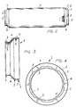
- Figure 1 is a side perspective view illustrating a pair of ring nuts according to the present invention;
- Figure 2 is a partially cross-sectioned view illustrating a printing cylinder and clearly showing the groove or rib arrangement including a plurality of ribs peripherally provided on the outer cylindric surface of the ring nut;
- Figures 3 and 4 are two different side views of a ring nut, provided with a ribbed or grooved arrangement at a peripheral cylindric portion thereof;
- Figure 5 is a partially cross-sectioned side view of the ring nut shown in figure 4, clearly showing the mentioned ribs;
and - Figure 6 illustrates the printing cylinder including a pair of supporting ring-nuts connected by glueing.
- With reference to the number references of the figures of the accompanying drawings, the ring nut according to the present invention, which has been generally indicated by the
reference number 1, comprises acylindric portion 2, connected to anend piece 3 by a taperingportion 4. - The
end piece 3 comprisesridges 5 for connection to the driving elements of the fabric printing apparatus, in a per se known manner. - The surface of the
cylindric portion 2 is provided for supporting afabric printing cylinder 6, schematically shown in figure 6, and comprises aflat portion 7 and acylindric portion 2. - On the
flat portion 7 are formed a plurality of grooves or ribs, directly during the die-casting of the aluminium or aluminium alloy material constituting the ring nut. - The above mentioned ribs are preferably formed on one or two
circumferential portions 9, and are specifically designed for facilitating the glueing operation of thecylinder 6. - In particular, the
ring nut 1 according to the present invention is made by a die-casting process, so as to allow conventional mechanical machining operations to be eliminated. - Thus, it is possible to obtain a making accuracy within limits of the order of about 7/100 mm (and probably also less) and, accordingly, much greater than that which can be conventionally obtained, which is of the order from 10 to 15/100 mm.
- Moreover, the die-cast ring nut according to the present invention is already provided with ribs and has a surface roughness allowing the conventionally used adhesive materials to provide a firm gripping.
- The elimination of any mechanical machining operations on the ring nuts, in addition to the already mentioned advantages, allows moreover to obtain a perfectly "clean" ring nut, free of any metal particles susceptible to adhere to the ring nut during a mechanical machining operation.
- These impurities would require to clean the ring nut by solvents before assembling the ring nut on the fabric printing cylinder, with a consequent loss of time.
- From the above disclosure it should be apparent that the invention fully achieves the intended aim and objects, since a ribbed ring nut has been provided, which can be made by a simple die-casting process of an aluminium or aluminium alloy material, the ring nut having mechanical properties much greater than those of conventionally made ring nuts.
Claims (4)
- A ring nut for supporting fabric printing cylinders, characterized in that said ring nut is directly made by die-casting an aluminium or aluminium alloy material, said ring nut being provided with a plurality of gripping peripheral ribs allowing the ring nut to be firmly connected to a fabric printing cylinder constituted by a thin nickel sheet, having a thickness of about 1/10 mm, without any subsequent mechanical machining operations, thereby greatly reducing the making cost and allowing to provide high accuracy fabric printing cylinders.
- A ring nut, according to Claim 1, characterized in that said die-casting process provides ring nuts having a peripherally ribbed cylindric portion and with tolerances from 5 to a maximum of 7/100 mm.
- A ring nut, according to Claim 1, characterized in that said ring nut has a surface roughness providing, jointly with the die-cast ribs thereof, a firm gripping of the glue materials used for connecting a pair of ring nuts to a fabric printing cylinder, thereby providing a very compact fabric printing cylinder and preventing the ring nuts from detaching from said fabric printing cylinder during the fabric printing operation, as well as the consequent loss of yield due to a forced stopping of the fabric printing rotary apparatus.
- A method for making an improved fabric printing cylinder by using ring nuts according to Claim 1, characterized in that said method comprises the steps of providing a pair of high precision ring nuts already provided with a plurality of gripping ribs and made by an aluminium or aluminium material die-casting process, and glueing, without any further mechanical machining operations, said ring nuts to a nickel cylinder which is glued, at the side end portions thereof, to the ribbed cylindric surfaces of said ring nuts so as to provide a high precision printing cylinder.
Applications Claiming Priority (2)
| Application Number | Priority Date | Filing Date | Title |
|---|---|---|---|
| ITMI951003A IT1274520B (en) | 1995-05-17 | 1995-05-17 | ALUMINUM RING NUTS FOR CYLINDERS FOR THE PRINTING OF FABRICS, OBTAINED DIRECTLY BY DIE-CASTING, WITHOUT ANY PROCESSING |
| ITMI951003 | 1995-05-17 |
Publications (2)
| Publication Number | Publication Date |
|---|---|
| EP0743180A2 true EP0743180A2 (en) | 1996-11-20 |
| EP0743180A3 EP0743180A3 (en) | 1996-11-27 |
Family
ID=11371618
Family Applications (1)
| Application Number | Title | Priority Date | Filing Date |
|---|---|---|---|
| EP96830264A Withdrawn EP0743180A3 (en) | 1995-05-17 | 1996-05-08 | Unmachined die-cast aluminium end ring for a cylindrical screen |
Country Status (2)
| Country | Link |
|---|---|
| EP (1) | EP0743180A3 (en) |
| IT (1) | IT1274520B (en) |
Cited By (2)
| Publication number | Priority date | Publication date | Assignee | Title |
|---|---|---|---|---|
| EP2607013A3 (en) * | 2011-12-22 | 2017-05-03 | MAGNA BDW technolgies GmbH | Method for manufacturing cylindrical components |
| CN109789698A (en) * | 2016-09-26 | 2019-05-21 | 小森公司 | Method for measuring varnish film thickness of printed matter and device for measuring varnish film thickness |
Family Cites Families (1)
| Publication number | Priority date | Publication date | Assignee | Title |
|---|---|---|---|---|
| US3858507A (en) * | 1973-04-09 | 1975-01-07 | Cranston Print Works Co | Cylindrical stencil with plastic end rings |
-
1995
- 1995-05-17 IT ITMI951003A patent/IT1274520B/en active IP Right Grant
-
1996
- 1996-05-08 EP EP96830264A patent/EP0743180A3/en not_active Withdrawn
Cited By (2)
| Publication number | Priority date | Publication date | Assignee | Title |
|---|---|---|---|---|
| EP2607013A3 (en) * | 2011-12-22 | 2017-05-03 | MAGNA BDW technolgies GmbH | Method for manufacturing cylindrical components |
| CN109789698A (en) * | 2016-09-26 | 2019-05-21 | 小森公司 | Method for measuring varnish film thickness of printed matter and device for measuring varnish film thickness |
Also Published As
| Publication number | Publication date |
|---|---|
| ITMI951003A1 (en) | 1996-11-17 |
| IT1274520B (en) | 1997-07-17 |
| EP0743180A3 (en) | 1996-11-27 |
| ITMI951003A0 (en) | 1995-05-17 |
Similar Documents
| Publication | Publication Date | Title |
|---|---|---|
| GB1582321A (en) | Clamping apparatus | |
| US5062363A (en) | Flexible printing plate attachment system | |
| US4471846A (en) | Clamping arrangement | |
| US4376414A (en) | Printing plate attachment arrangement | |
| CN216577682U (en) | Mounting tool for nut of supporting plate | |
| US6647879B1 (en) | Bridge sleeve for printing apparatus | |
| US3858507A (en) | Cylindrical stencil with plastic end rings | |
| US20040037638A1 (en) | Clamping mechanism | |
| US5188463A (en) | Bearing for the shaft of a canned motor pump | |
| JP3834159B2 (en) | Shaft fastening device for shaft coupling | |
| US4017022A (en) | Centrifuge arrangement and method of making a conical container therefor | |
| JPH06129936A (en) | Collet chuck for balance measurement | |
| GB2069660A (en) | Device for securing a cylinder drive gear to a shaft | |
| JP2880753B2 (en) | Chuck for torsional testing machine | |
| CN212858555U (en) | Roller shaft turning clamp | |
| JPH09174332A (en) | Blade built-in hob | |
| JP2005066758A (en) | Collet chuck | |
| JPH08145072A (en) | Connecting mechanism for roll shaft and universal coupling | |
| CN223656340U (en) | Frock is used in processing of monofilament head | |
| CN111002079B (en) | High-precision double-layer self-centering clamping fixture and clamping method | |
| JPH06315812A (en) | Copying cutting device such as beveling machine | |
| JPS6114749Y2 (en) | ||
| JP3028743U (en) | Fastening mechanism | |
| JP2004106838A (en) | Crank and crankshaft for bicycle | |
| CN217860002U (en) | Spring clearance-eliminating auxiliary positioning fixture for lead screw |
Legal Events
| Date | Code | Title | Description |
|---|---|---|---|
| PUAI | Public reference made under article 153(3) epc to a published international application that has entered the european phase |
Free format text: ORIGINAL CODE: 0009012 |
|
| PUAL | Search report despatched |
Free format text: ORIGINAL CODE: 0009013 |
|
| AK | Designated contracting states |
Kind code of ref document: A2 Designated state(s): DE ES FR GB NL |
|
| AK | Designated contracting states |
Kind code of ref document: A3 Designated state(s): DE ES FR GB NL |
|
| STAA | Information on the status of an ep patent application or granted ep patent |
Free format text: STATUS: THE APPLICATION IS DEEMED TO BE WITHDRAWN |
|
| 18D | Application deemed to be withdrawn |
Effective date: 19970528 |