EP0742441A1 - Current sensor - Google Patents
Current sensor Download PDFInfo
- Publication number
- EP0742441A1 EP0742441A1 EP96400906A EP96400906A EP0742441A1 EP 0742441 A1 EP0742441 A1 EP 0742441A1 EP 96400906 A EP96400906 A EP 96400906A EP 96400906 A EP96400906 A EP 96400906A EP 0742441 A1 EP0742441 A1 EP 0742441A1
- Authority
- EP
- European Patent Office
- Prior art keywords
- magnetoresistive
- ammeter
- conductor
- current
- ammeter according
- Prior art date
- Legal status (The legal status is an assumption and is not a legal conclusion. Google has not performed a legal analysis and makes no representation as to the accuracy of the status listed.)
- Withdrawn
Links
Images


Classifications
-
- G—PHYSICS
- G01—MEASURING; TESTING
- G01R—MEASURING ELECTRIC VARIABLES; MEASURING MAGNETIC VARIABLES
- G01R15/00—Details of measuring arrangements of the types provided for in groups G01R17/00 - G01R29/00, G01R33/00 - G01R33/26 or G01R35/00
- G01R15/14—Adaptations providing voltage or current isolation, e.g. for high-voltage or high-current networks
- G01R15/20—Adaptations providing voltage or current isolation, e.g. for high-voltage or high-current networks using galvano-magnetic devices, e.g. Hall-effect devices, i.e. measuring a magnetic field via the interaction between a current and a magnetic field, e.g. magneto resistive or Hall effect devices
- G01R15/205—Adaptations providing voltage or current isolation, e.g. for high-voltage or high-current networks using galvano-magnetic devices, e.g. Hall-effect devices, i.e. measuring a magnetic field via the interaction between a current and a magnetic field, e.g. magneto resistive or Hall effect devices using magneto-resistance devices, e.g. field plates
Definitions
- the invention relates to an ammeter and more particularly to an ammeter comprising a magnetosensitive element with planar Hall effect. It is also applicable to a differential circuit breaker.
- French patent application No. 93 15551 describes a weak magnetic field sensor based on a planar Hall effect magnetosensitive element.
- Such a sensor is based on the transverse measurement of the anisotropic magnetoresistance effect in a thin ferromagnetic film.
- Figure 1 shows the magnetosensitive layer.
- a current I flows in a direction XX 'of the layer and the resistivity is measured in the direction YY'.
- This resistivity varies as a function of the magnetization M applied to the sensor.
- planar Hall effect sensors compared to magnetoresistive sensors with longitudinal measurement are on the one hand a great simplification of the associated technology, on the other hand a reduction of approximately four orders of magnitude of the thermal drift, principal low frequency noise component (around 1Hz).
- this sensor can be made sensitive only to the component of the magnetic field perpendicular to its direction of supply. Its size can be reduced up to dimensions smaller than that of the magnetic domains, which eliminates the source of noise associated with wall movements.
- a substrate 5 carries an element 1, preferably square but possibly rectangular, in a thin layer of a magnetoresistive material making it possible to obtain a planar Hall effect.
- this material has an anisotropy oriented in the plane of the layer.
- the thickness of the layer is between 0.01 and 1 ⁇ m (0.02 ⁇ m for example) and the width and length of the element 1 are between 10 and 50 ⁇ m (20 ⁇ m for example).
- connection pads 2 ′, 2 ′′ for connecting a current supply device 2 allowing the circulation of a current i in the element 1.
- This current i is preferably continuous and constant.
- connection elements 3 'and 3 are connected on either side of the element 1 along an axis YY' perpendicular to the axis XX '. These connection elements make it possible to connect a device 3 for measuring voltage or resistivity.
- the connection areas 2 ', 2 "and 3', 3" are each the width of one side of the element 1. In addition, provision is made for a rapid increase in the width of these connection areas in order to reduce the related limitations. to Johnson noise as well as electrical dissipation.
- Element 1 is covered with an insulating layer 6.
- Means are provided on the insulating layer to allow the flow of a current I to be measured such as a conductor 4.
- the circulation of an electric current in the conductor 4 (direct or alternating) generates a transverse magnetic field (in the direction ZZ ') which can be detected by the sensor.
- a transverse magnetic field in the direction ZZ '
- the choice of insulator separating the conductor 4 from the layer 1 depends on the range of current to be measured. This insulator can either be a layer deposited on layer 1 or be a calibrated free space.
- the only constraint is that the wire must be parallel to the direction of supply of the sensor so that the magnetic field associated with the circulation of an electric current in this conductor has at least one transverse component at the level of the sensor. In particular, it is not necessary for this conductor to be located directly above the sensor as indicated in FIG. 2.
- a geometry 1 sensor will measure currents from 5 ⁇ A to 500mA.
- a sensor in geometry 2 will measure currents ranging from 300 ⁇ A to 30A.
- the curve in FIG. 3 represents an example of the response of an ammeter according to the invention.
- FIG. 4 represents an alternative embodiment according to the invention in which the conductor 4 is located on the face of the substrate 5 opposite to that carrying the element 1.
- the substrate must then be insulating and its thickness determines the distance D separating the element 1 of conductor 4.
- FIG. 5a provides on the rear face of the substrate opposite to the element 1, means making it possible to position along the axis ZZ ′, a conductor in which a current flows whose intensity I must be measured. These means positioning may be marks drawn on the substrate.
- a groove 7 has been provided in which the conductor is placed.
- bosses instead of the groove.
- FIG. 5b is a variant of FIG. 5a according to which the groove 7 is located in the layer of insulation 6.
- This improvement allows a more precise measurement of the current in the case of a wire whose size (diameter of the wire + sheath) is of the same order of magnitude as the distance between the wire and the sensor.
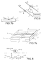
- FIG. 8 shows a particular example with three sensors C1, C2, C3 placed side by side on a substrate.
- the ammeter can be produced in the form of a clamp 7 such as an ammeter clamp (FIG. 5c), making it possible to place the conductor in front of the sensitive element 1 of the ammeter which is then located in a branch of the clamp near the conductor 4.
- a clamp 7 such as an ammeter clamp (FIG. 5c)
- the invention also relates to the differential measurement of two currents flowing in two conductors.
- FIG. 6 represents an ammeter making it possible to carry out a differential measurement of current in two conductors 4 and 4 ′, in which currents of intensities le and ls circulate, with the sensors C4 and C5.
- the intensities of the currents le and ls are measured separately, each using two sensors described above.
- the sensor output signals are then possibly amplified before being compared.
- the applications of this invention relate in particular to differential circuit breakers. Measuring the difference in intensity between the finish line (le) and the output outlet (ls) makes it possible to detect leaks and therefore cut off the flow of current.
- the invention is equally applicable to direct current installations (electronics, navigation) and / or alternating current installations.
- Figure 7a is a way of making a differential ammeter and is derived from the embodiment of Figure 2. It has on each side of the sensor, a conductor 4 and 4 '.
- the conductor 4 is located on the insulating layer 6 and the conductor 4 'is located on the face of the substrate 5 opposite to that carrying the sensitive element 1.
- the insulating layer 3 and the substrate 5 have the same thickness so that the conductors 4, 4 'are at the same distance from the element 1. Provision is made for the currents flowing in the conductors 4 and 4' to be in opposite directions and to be in phase. If these conditions are met, and the currents are equal, the magnetic fields induced by these currents cancel each other out in element 1. On the other hand, if they are not equal, the magnetic field of the strongest current predominates and a non-zero voltage is detected at terminals 3-3 '.
- a differential ammeter can also be produced by providing the conductors 4 and 4 'on the same face of the sensor, for example on the insulating layer 6. The conductors 4 and 4' are then positioned so as to be at the same distance from the sensitive element 1 of the sensor.
Landscapes
- Physics & Mathematics (AREA)
- General Physics & Mathematics (AREA)
- Measuring Instrument Details And Bridges, And Automatic Balancing Devices (AREA)
- Hall/Mr Elements (AREA)
- Measuring Magnetic Variables (AREA)
Abstract
Description
L'invention concerne un ampèremètre et plus particulièrement un ampèremètre comportant un élément magnétosensible à effet Hall planaire. Elle est applicable également à un disjoncteur différentiel.The invention relates to an ammeter and more particularly to an ammeter comprising a magnetosensitive element with planar Hall effect. It is also applicable to a differential circuit breaker.
La demande de brevet français n° 93 15551 décrit un senseur de champ magnétique faible à base d'un élément magnétosensible à effet Hall planaire.French patent application No. 93 15551 describes a weak magnetic field sensor based on a planar Hall effect magnetosensitive element.
Un tel senseur repose sur la mesure transverse de l'effet de magnétorésistance anisotrope dans un film mince ferromagnétique. La figure 1 représente la couche magnétosensible. Un courant I circule selon une direction XX' de la couche et on mesure la résistivité selon la direction YY'. Cette résistivité varie en fonction de l'aimantation M appliquée au senseur. De plus, elle est fonction de l'angle θ entre l'aimantation et la direction XX' du courant :![]()
![]()
Les deux principaux avantages des capteurs à effet Hall planaire par rapport aux capteurs magnétorésistifs à mesure longitudinale sont d'une part une grande simplification de la technologie associée, d'autre part une réduction d'environ quatre ordres de grandeur de la dérive thermique, principale composante de bruit à faible fréquence (autour de 1Hz). Par construction, ce capteur peut être rendu sensible uniquement à la composante du champ magnétique perpendiculaire à sa direction d'alimentation. Sa taille peut être réduite jusqu'à des dimensions inférieures à celle des domaines magnétiques, ce qui permet d'éliminer la source de bruit associée aux mouvements de parois. Nous avons mesuré, sur des prototypes de tels capteurs, une réponse linéaire sur quatre ordres de grandeurs (voir document A. Schuhl, F. Nguyen-Van-Dau and J.R. Childress, Applied Physics Letters, 66 15 Mai 1995).The two main advantages of planar Hall effect sensors compared to magnetoresistive sensors with longitudinal measurement are on the one hand a great simplification of the associated technology, on the other hand a reduction of approximately four orders of magnitude of the thermal drift, principal low frequency noise component (around 1Hz). By construction, this sensor can be made sensitive only to the component of the magnetic field perpendicular to its direction of supply. Its size can be reduced up to dimensions smaller than that of the magnetic domains, which eliminates the source of noise associated with wall movements. We have measured, on prototypes of such sensors, a linear response over four orders of magnitude (see document A. Schuhl, F. Nguyen-Van-Dau and J.R. Childress, Applied Physics Letters, 66 May 15, 1995).
L'invention concerne donc un ampèremètre comprenant :
- un élément en matériau magnétorésistif en couche mince situé sur une première face d'un substrat;
- des premiers moyens de connexion connectés à l'élément magnétorésistif en deux zones situées selon une première direction (XX') et permettant une alimentation en courant de l'élément ;
- des deuxièmes moyens de connexion connectés à l'élément magnétorésistif en deux zones situées selon une deuxième direction (YY') perpendiculaire à la première direction.
- an element made of magnetoresistive material in a thin layer located on a first face of a substrate;
- first connection means connected to the magnetoresistive element in two zones located in a first direction (XX ') and allowing a current supply of the element;
- second connection means connected to the magnetoresistive element in two zones located in a second direction (YY ') perpendicular to the first direction.
Les différents objets et caractéristiques de l'invention apparaîtront plus clairement dans la description qui va suivre et dans les figures annexées qui représentent:
- la figure 1, un dispositif à effet Hall planaire déjà décrit précédemment ;
- la figure 2, un exemple de réalisation d'un dispositif selon l'invention ;
- la figure 3, une courbe de réponse d'un ampèremètre selon l'invention ;
- la figure 4, une variante de l'ampèremètre de la figure 2 ;
- les figures 5a à 5c, des moyens de mise en position d'un conducteur dont on veut mesurer le courant ;
- la figure 6, un circuit d'ampèremètre différentiel ;
- les figures 7a et 7b, un ampèremètre différentiel plus compact appliquant l'ampèremètre selon l'invention ;
- la figure 8, un ampèremètre à plusieurs capteurs ne nécessitant pas de dispositif de mise en place du conducteur.
- Figure 1, a planar Hall effect device already described above;
- Figure 2, an embodiment of a device according to the invention;
- FIG. 3, a response curve of an ammeter according to the invention;
- Figure 4, a variant of the ammeter of Figure 2;
- Figures 5a to 5c, means for positioning a conductor whose current is to be measured;
- FIG. 6, a differential ammeter circuit;
- Figures 7a and 7b, a more compact differential ammeter applying the ammeter according to the invention;
- Figure 8, an ammeter with several sensors does not require a driver placement device.
En se reportant à la figure 2, on va donc décrire un exemple de réalisation d'un ampèremètre selon l'invention.Referring to Figure 2, we will therefore describe an embodiment of an ammeter according to the invention.
Un substrat 5 porte un élément 1, de préférence carré mais pouvant être rectangulaire, en couche mince d'un matériau magnétorésistif permettant d'obtenir un effet Hall planaire. De préférence, ce matériau présente une anisotropie orientée dans le plan de la couche. A titre d'exemple, l'épaisseur de la couche est comprise entre 0,01 et 1 µm (0,02 µm par exemple) et la largeur et la longueur de l'élément 1 sont comprises entre 10 et 50 µm (20 µm par exemple). Selon un axe XX' l'élément 1 possède à ces deux extrémités des plages de connexion 2', 2" permettant de connecter un appareil d'alimentation en courant 2 permettant la circulation d'un courant i dans l'élément 1. Ce courant i est de préférence continu et constant.A
Deux éléments de connexion 3' et 3" sont connectés de part et d'autre de l'élément 1 selon un axe YY' perpendiculaire à l'axe XX'. Ces éléments de connexion permettent de connecter un appareil de mesure 3 de tension ou de résistivité. Les plages de connexions 2', 2" et 3', 3" font chacune la largeur d'un côté de l'élément 1. De plus, on prévoit une augmentation rapide de la largeur de ces plages de connexion pour diminuer les limitations liées au bruit de Johnson ainsi que la dissipation électrique.Two
L'élément 1 est recouvert d'une couche d'isolant 6.
Sur la couche d'isolant est prévu des moyens pour permettre la circulation d'un courant I à mesurer tel qu'un conducteur 4.Means are provided on the insulating layer to allow the flow of a current I to be measured such as a
La circulation d'un courant électrique dans le conducteur 4 (continu ou alternatif) génère un champ magnétique transversal (selon la direction ZZ') qui peut être détecté par le capteur. Comme nous le verrons dans le calcul d'ordre de grandeur ci-dessous, il est avantageux de se placer dans la limite ou le conducteur est large vis-à-vis de la distance le séparant de la couche sensible 1 du capteur. Le choix de l'isolant séparant le conducteur 4 de la couche 1 dépend de la gamme de courant à mesurer. Cet isolant peut soit être une couche déposée sur la couche 1 soit être un espace libre calibré. La seule contrainte est que le fil doit être parallèle à la direction d'alimentation du capteur de telle manière que le champ magnétique associé à la circulation d'un courant électrique dans ce conducteur ait au moins une composante transversale au niveau du capteur. En particulier, il n'est pas nécessaire que ce conducteur soit situé à l'aplomb du capteur comme cela est indiqué sur la figure 2.The circulation of an electric current in the conductor 4 (direct or alternating) generates a transverse magnetic field (in the direction ZZ ') which can be detected by the sensor. As we will see in the order of magnitude calculation below, it is advantageous to place oneself within the limit where the conductor is large with respect to the distance separating it from the
Le calcul de l'amplitude du champ magnétique induit au niveau du capteur par un courant de mesure d'amplitude l, conduit à l'expression :![]()
![]()
-
L est la largeur du conducteur 4 transportant le courant à mesurer ;L is the width of the
conductor 4 carrying the current to be measured; -
D est la distance entre le conducteur 4 et la couche 1.D is the distance between
conductor 4 andlayer 1.
Lorsque L2D>>1, on a B∼µ0l/2L.When L2D >> 1, we have B∼µ 0 l / 2L.
Ainsi dans le cas limite où L » 2D la sensibilité de l'ampèremètre est indépendante de la distance entre la ligne de courant 4 et l'élément sensible 1.Thus in the borderline case where L 2D 2D the sensitivity of the ammeter is independent of the distance between the
Pour se rendre compte de l'intérêt de l'invention nous donnons ici deux exemples d'applications de l'invention correspondant à deux géométries distinctes avec un même élément sensible détectant des champs magnétiques compris entre 10 nT et 1 mT.To realize the interest of the invention here we give two examples of applications of the invention corresponding to two distinct geometries with the same sensitive element detecting magnetic fields between 10 nT and 1 mT.
A titre d'exemple, nous considérons ci-dessous deux configurations possibles :As an example, we consider below two possible configurations:
Géométrie 1 : L = 300 µm et D = 1 µm conduisent à B/I = 2.1 mT/A = 21 mG/mAGeometry 1: L = 300 µm and D = 1 µm lead to B / I = 2.1 mT / A = 21 mG / mA
Géométrie 2 : L = 1 cm et D = 1 mm conduisent à B/l = 3.15 10-5T/A = 0.315G/AGeometry 2: L = 1 cm and D = 1 mm lead to B / l = 3.15 10- 5 T / A = 0.315G / A
Un capteur dans la géométrie 1 mesurera des courants allant de 5µA à 500 mA. Un capteur dans la géométrie 2 mesurera des courants allant de 300 µA à 30A. Pour une sensibilité typique du capteur de 100 V/T.A et une alimentation de la couche 1 du capteur par un courant de 10 mA, on aboutit à une sensibilité de l'ampèremètre de 2,1 mV/A pour la géométrie 1 et 31.5 µV/A pour la géométrie 2.A
La courbe de la figure 3 représente un exemple de réponse d'un ampèremètre selon l'invention.The curve in FIG. 3 represents an example of the response of an ammeter according to the invention.
La figure 4 représente une variante de réalisation selon l'invention dans laquelle le conducteur 4 est située sur la face du substrat 5 opposée à celle portant l'élément 1. Le substrat doit alors être isolant et son épaisseur détermine la distance D séparant l'élément 1 du conducteur 4.FIG. 4 represents an alternative embodiment according to the invention in which the
On peut réaliser à l'aide d'un capteur à effet Hall planaire ainsi décrit un ampèremètre sans contact, c'est-à-dire un dispositif permettant de mesurer le courant circulant dans un élément de circuit électrique (par exemple un fil) sans avoir à se brancher sur celui-ci. Pour cela comme représenté en figures 5a et 5b, on prévoit un logement mécanique de l'élément de circuit 4 permettant une distance contrôlée du capteur. Par exemple, la figure 5a prévoit sur la face arrière du substrat opposée à l'élément 1, des moyens permettant de positionner selon l'axe ZZ', un conducteur dans lequel circule un courant dont on doit mesurer l'intensité I. Ces moyens de positionnement peuvent être des repères dessinés sur le substrat. Selon la figure 5a, on a prévu une gorge 7 dans laquelle on vient placer le conducteur. On aurait pu également prévoir des bossages au lieu de la gorge.It is possible to produce, using a planar Hall effect sensor thus described, a contactless ammeter, that is to say a device making it possible to measure the current flowing in an electrical circuit element (for example a wire) without have to plug into it. For this as shown in Figures 5a and 5b, there is provided a mechanical housing of the
La figure 5b est une variante de la figure 5a selon laquelle la gorge 7 est située dans la couche d'isolant 6.FIG. 5b is a variant of FIG. 5a according to which the
Le problème associé à la méconnaissance de la dimension transversale L de l'élément de circuit 4 ou au fait que cette dimension puisse ne pas être nettement supérieure à la distance entre l'élément et le capteur peut être résolu en disposant plusieurs capteurs transversalement par rapport à la circulation du courant à mesurer. La mesure effectuée sur chacun des capteurs et la connaissance de la distance les séparant permet de remonter aux deux inconnues : la dimension latérale de l'élément de circuit et l'intensité du courant.The problem associated with the ignorance of the transverse dimension L of the
Cette amélioration permet une mesure plus précise du courant dans le cas d'un fil dont la taille (diamètre du fil + gaine) est du même ordre de grandeur que la distance entre le fil et le capteur.This improvement allows a more precise measurement of the current in the case of a wire whose size (diameter of the wire + sheath) is of the same order of magnitude as the distance between the wire and the sensor.
La figure 8 montre un exemple particulier avec trois capteurs C1, C2, C3 placés côte à côte sur un substrat.FIG. 8 shows a particular example with three sensors C1, C2, C3 placed side by side on a substrate.
Le fonctionnement d'un tel dispositif est le suivant. On bouge l'ensemble de capteurs jusqu'à obtenir une réponse identique sur C1 et sur C3. Le courant l à mesurer est alors donné par :
Pour des questions de commodité d'utilisation, l'ampèremètre peut être réalisé sous forme d'une pince 7 telle qu'une pince ampèremétrique (figure 5c), permettant de mettre en place le conducteur devant l'élément sensible 1 de l'ampèremètre qui est alors situé dans une branche de la pince à proximité du conducteur 4.For convenience of use, the ammeter can be produced in the form of a
Selon une forme de réalisation plus générale et plus sommaire, on peut également ne pas prévoir de moyen de mise en position du conducteur dont on veut mesurer le courant. On se borne alors à mettre la partie sensible de l'ampèremètre (l'élément 1) à proximité du conducteur et on le fait tourner de façon à obtenir une valeur maximale de la tension (ou de la résistivité). Cette valeur maximale donnant la valeur de mesure.According to a more general and more summary embodiment, it is also possible not to provide means for positioning the conductor whose current is to be measured. We then limit ourselves to putting the sensitive part of the ammeter (element 1) close to the conductor and we rotate it so as to obtain a maximum value of the voltage (or resistivity). This maximum value giving the measurement value.
L'invention concerne aussi la mesure différentielle de deux courants circulant dans deux conducteurs.The invention also relates to the differential measurement of two currents flowing in two conductors.
La figure 6 représente un ampèremètre permettant de réaliser une mesure différentielle de courant dans deux conducteurs 4 et 4', dans lesquels circulent des courants d'intensités le et ls, avec les capteurs C4 et C5.FIG. 6 represents an ammeter making it possible to carry out a differential measurement of current in two
Les intensités des courants le et ls sont mesurées séparément, chacune à l'aide de deux capteurs décrits précédemment. Les signaux de sortie des capteurs sont alors éventuellement amplifiés avant d'être comparés.The intensities of the currents le and ls are measured separately, each using two sensors described above. The sensor output signals are then possibly amplified before being compared.
Les applications de cette invention concernent en particulier les disjoncteurs différentiels. La mesure de la différence d'intensité entre la ligne d'arrivée (le) et la sortie de sortie (ls) permet de détecter les fuites et donc de couper l'arrivée du courant.The applications of this invention relate in particular to differential circuit breakers. Measuring the difference in intensity between the finish line (le) and the output outlet (ls) makes it possible to detect leaks and therefore cut off the flow of current.
L'invention s'applique aussi bien aux installations en courant continu (électronique, navigation) et/ou installation en courant alternatif.The invention is equally applicable to direct current installations (electronics, navigation) and / or alternating current installations.
La figure 7a est une façon de réaliser un ampèremètre différentiel et est dérivé du mode de réalisation de la figure 2. ll comporte de chaque côté du capteur, un conducteur 4 et 4'. Le conducteur 4 est localisé sur la couche d'isolant 6 et le conducteur 4' est localisé sur la face du substrat 5 opposée à celle portant l'élément sensible 1. La couche d'isolant 3 et le substrat 5 ont même épaisseur pour que les conducteurs 4, 4' soient à la même distance de l'élément 1. On prévoit que les courants qui circulent dans les conducteurs 4 et 4' soient de sens opposés et soient en phase. Si ces conditions sont respectées, et que les courant sont égaux, les champs magnétiques induits par ces courants s'annulent dans l'élément 1. Par contre, s'ils ne sont pas égaux, le champ magnétique du courant le plus fort prédomine et une tension non nulle est détectée aux bornes 3-3'.Figure 7a is a way of making a differential ammeter and is derived from the embodiment of Figure 2. It has on each side of the sensor, a
Selon une variante de réalisation représenté en figure 7b, un ampèremètre différentiel peut être également réalisé en prévoyant les conducteurs 4 et 4' sur la même face du capteur, par exemple sur la couche d'isolant 6. Les conducteurs 4 et 4' sont alors positionnés de façon à être à une même distance de l'élément sensible 1 du capteur.According to an alternative embodiment shown in FIG. 7b, a differential ammeter can also be produced by providing the
Claims (14)
Applications Claiming Priority (2)
| Application Number | Priority Date | Filing Date | Title |
|---|---|---|---|
| FR9505659 | 1995-05-12 | ||
| FR9505659A FR2734058B1 (en) | 1995-05-12 | 1995-05-12 | AMMETER |
Publications (1)
| Publication Number | Publication Date |
|---|---|
| EP0742441A1 true EP0742441A1 (en) | 1996-11-13 |
Family
ID=9478926
Family Applications (1)
| Application Number | Title | Priority Date | Filing Date |
|---|---|---|---|
| EP96400906A Withdrawn EP0742441A1 (en) | 1995-05-12 | 1996-04-26 | Current sensor |
Country Status (4)
| Country | Link |
|---|---|
| US (1) | US5686879A (en) |
| EP (1) | EP0742441A1 (en) |
| JP (1) | JPH08304466A (en) |
| FR (1) | FR2734058B1 (en) |
Cited By (1)
| Publication number | Priority date | Publication date | Assignee | Title |
|---|---|---|---|---|
| WO2010082115A1 (en) | 2009-01-13 | 2010-07-22 | Seneca S.R.L. | Method for measuring an electrical current |
Families Citing this family (21)
| Publication number | Priority date | Publication date | Assignee | Title |
|---|---|---|---|---|
| EP0874244B1 (en) * | 1997-04-19 | 2002-01-30 | LUST ANTRIEBSTECHNIK GmbH | Procedure and apparatus for measuring electric currents in conductors |
| FR2771511B1 (en) | 1997-11-25 | 2000-02-04 | Thomson Csf | MAGNETIC FIELD SENSOR AND MANUFACTURING METHOD THEREOF |
| US6473220B1 (en) * | 1998-01-22 | 2002-10-29 | Trivium Technologies, Inc. | Film having transmissive and reflective properties |
| JP2001059851A (en) * | 1999-08-20 | 2001-03-06 | Yazaki Corp | Apparatus and method for detection of current |
| FR2809185B1 (en) | 2000-05-19 | 2002-08-30 | Thomson Csf | MAGNETIC FIELD SENSOR USING MAGNETO RESISTANCE, AND MANUFACTURING METHOD |
| FR2817077B1 (en) | 2000-11-17 | 2003-03-07 | Thomson Csf | VARIABLE VOLTAGE CONTROLABLE CAPACITY USING THE "COULOMB BLOCKING" PHENOMENON |
| DE10105186A1 (en) * | 2001-02-06 | 2002-08-29 | Bosch Gmbh Robert | Semiconductor device, ammeter and motor vehicle |
| FR2828001B1 (en) * | 2001-07-27 | 2003-10-10 | Thales Sa | DEVICE FOR CONTROLLING MAGNETIC DIRECTION WITHOUT EXTERNAL MAGNETIC FIELD |
| US7595934B2 (en) | 2002-03-26 | 2009-09-29 | Brilliant Film Llc | Integrated sub-assembly having a light collimating or transflecting device |
| US7259545B2 (en) * | 2003-02-11 | 2007-08-21 | Allegro Microsystems, Inc. | Integrated sensor |
| TW200506446A (en) * | 2003-05-20 | 2005-02-16 | Trivium Technologies Inc | Devices for use in non-emissive displays |
| US7684147B2 (en) * | 2003-12-15 | 2010-03-23 | Univ Bar Ilan | Magnetoelectronic devices based on colossal magnetoresistive thin films |
| FR2880131B1 (en) * | 2004-12-23 | 2007-03-16 | Thales Sa | METHOD FOR MEASURING LOW MAGNETIC FIELD AND MAGNETIC FIELD SENSOR WITH IMPROVED SENSITIVITY |
| US7768083B2 (en) * | 2006-01-20 | 2010-08-03 | Allegro Microsystems, Inc. | Arrangements for an integrated sensor |
| FR2911690B1 (en) | 2007-01-19 | 2009-03-06 | Thales Sa | MAGNETIC AMPLIFICATION DEVICE COMPRISING A MAGNETIC SENSOR WITH LONGITUDINAL SENSITIVITY |
| TW200946775A (en) | 2008-02-27 | 2009-11-16 | Brilliant Film Llc | Concentrators for solar power generating systems |
| AT506682B1 (en) * | 2008-04-17 | 2014-05-15 | Adaptive Regelsysteme Ges M B H | CURRENT MEASURING DEVICE AND METHOD FOR THE GALVANICALLY SEPARATED MEASUREMENT OF FLOWS |
| US7816905B2 (en) * | 2008-06-02 | 2010-10-19 | Allegro Microsystems, Inc. | Arrangements for a current sensing circuit and integrated current sensor |
| US9976876B2 (en) | 2015-11-24 | 2018-05-22 | Allegro Microsystems, Llc | Methods and apparatus for phase selection in ring magnet sensing |
| US10935612B2 (en) | 2018-08-20 | 2021-03-02 | Allegro Microsystems, Llc | Current sensor having multiple sensitivity ranges |
| US11567108B2 (en) | 2021-03-31 | 2023-01-31 | Allegro Microsystems, Llc | Multi-gain channels for multi-range sensor |
Citations (2)
| Publication number | Priority date | Publication date | Assignee | Title |
|---|---|---|---|---|
| US3693085A (en) * | 1971-07-15 | 1972-09-19 | Gen Motors Corp | System for calibrated high level current measurement using a magnetic field responsive transistor |
| US5172052A (en) * | 1990-07-23 | 1992-12-15 | Iimorrow, Inc. | Current sensor assembly and method |
Family Cites Families (5)
| Publication number | Priority date | Publication date | Assignee | Title |
|---|---|---|---|---|
| FR2666175B1 (en) * | 1990-08-21 | 1992-10-16 | Thomson Csf | SUPERCONDUCTING FIELD EFFECT TRANSISTOR. |
| FR2674067B1 (en) * | 1991-03-15 | 1993-05-28 | Thomson Csf | SEMICONDUCTOR DEVICE WITH JOSEPHSON EFFECT. |
| FR2675951B1 (en) * | 1991-04-23 | 1997-08-29 | Thomson Csf | JOSEPHSON JUNCTION STRUCTURE. |
| FR2685489B1 (en) * | 1991-12-23 | 1994-08-05 | Thomson Csf | LOW MAGNETIC FIELD SENSOR WITH MAGNETORESISTIVE EFFECT. |
| FR2702919B1 (en) * | 1993-03-19 | 1995-05-12 | Thomson Csf | Magnetoresistive transducer and production method. |
-
1995
- 1995-05-12 FR FR9505659A patent/FR2734058B1/en not_active Expired - Fee Related
-
1996
- 1996-04-26 EP EP96400906A patent/EP0742441A1/en not_active Withdrawn
- 1996-04-30 US US08/641,033 patent/US5686879A/en not_active Expired - Fee Related
- 1996-05-10 JP JP8116706A patent/JPH08304466A/en active Pending
Patent Citations (2)
| Publication number | Priority date | Publication date | Assignee | Title |
|---|---|---|---|---|
| US3693085A (en) * | 1971-07-15 | 1972-09-19 | Gen Motors Corp | System for calibrated high level current measurement using a magnetic field responsive transistor |
| US5172052A (en) * | 1990-07-23 | 1992-12-15 | Iimorrow, Inc. | Current sensor assembly and method |
Cited By (1)
| Publication number | Priority date | Publication date | Assignee | Title |
|---|---|---|---|---|
| WO2010082115A1 (en) | 2009-01-13 | 2010-07-22 | Seneca S.R.L. | Method for measuring an electrical current |
Also Published As
| Publication number | Publication date |
|---|---|
| US5686879A (en) | 1997-11-11 |
| FR2734058A1 (en) | 1996-11-15 |
| FR2734058B1 (en) | 1997-06-20 |
| JPH08304466A (en) | 1996-11-22 |
Similar Documents
| Publication | Publication Date | Title |
|---|---|---|
| EP0742441A1 (en) | Current sensor | |
| FR2752302A1 (en) | MAGNETIC FIELD SENSOR WITH MAGNETORESISTANCE BRIDGE | |
| EP0692098B1 (en) | Electric current measuring device with a magnetic flux sensor, in particular for electric vehicles | |
| FR2750769A1 (en) | THIN FILM MAGNETIC FIELD SENSOR | |
| FR2904425A1 (en) | Electric current e.g. direct electric current, measuring device for microelectronic device, has microsensor including magnetic circuit with cores, and detection coil producing inverse feedback magnetic field opposite to magnetic field | |
| EP0849799A1 (en) | Bispectral photoconductive detector | |
| EP1046021B1 (en) | Linear angular sensor with magnetoresistors | |
| FR2827962A1 (en) | Hall effect current sensor is chip with opposite bias sensors and calibration circuits | |
| EP0660128B1 (en) | Thin film magnetic field detector | |
| FR2746925A1 (en) | Sensor system for measuring electric current and voltage esp. for medium voltage conductor and ohmic voltage divider for voltage measurement also capacitive voltage divider | |
| FR2787197A1 (en) | MAGNETIC FIELD SENSOR WITH GIANT MAGNETORESISTANCE | |
| CA2227032A1 (en) | Hall-effect contactless position sensor | |
| EP2834658B1 (en) | Method and device for measuring a magnetic field and the temperature of a magneto-resistive transducer | |
| FR2826723A1 (en) | CAPACITIVE MEASUREMENT SYSTEM | |
| EP1692527B1 (en) | Current sensor with reduced sensitivity to stray magnetic fields | |
| WO2022090499A1 (en) | Device for detecting the capacitive coupling between an object and a detection surface | |
| EP2157402B1 (en) | Device for measuring the alignment of attached structures | |
| WO2021140043A1 (en) | Capacitive detection device comprising a module for biasing by induction | |
| FR2693797A1 (en) | Control system for pipes, especially bare or coated steel pipes. | |
| FR3006056A1 (en) | METHOD FOR MEASURING MAGNETIC EFFECT ELECTRIC CURRENT STRONG AND CORRESPONDING MEASURING DEVICE | |
| FR2504272A1 (en) | Integrated circuit transducer for measuring power in load - consists of diode bridge circuit of which diodes are positioned in magnetic field generated by load current | |
| FR2892762A1 (en) | Subsoil part, e.g. rock, magnetic imaging device, for e.g. gas reserve determination, has connecting unit mounting sensors in cooperation with shoes and arranged such that plane is constantly parallel to axis when tool moves in well | |
| EP0696720B1 (en) | Pendular sensor having unlimited rotation about its roll axis | |
| FR2644897A1 (en) | FLAME BEAM MICROMAGNETOMETER | |
| FR2782159A1 (en) | Device for detection of an attempt to break into a secure container has a system of wire type sensors connected to analysis electronics for determination of variations in resistance and hence break in attempts |
Legal Events
| Date | Code | Title | Description |
|---|---|---|---|
| PUAI | Public reference made under article 153(3) epc to a published international application that has entered the european phase |
Free format text: ORIGINAL CODE: 0009012 |
|
| AK | Designated contracting states |
Kind code of ref document: A1 Designated state(s): DE GB |
|
| 17P | Request for examination filed |
Effective date: 19970321 |
|
| RAP1 | Party data changed (applicant data changed or rights of an application transferred) |
Owner name: THALES |
|
| 17Q | First examination report despatched |
Effective date: 20030410 |
|
| STAA | Information on the status of an ep patent application or granted ep patent |
Free format text: STATUS: THE APPLICATION IS DEEMED TO BE WITHDRAWN |
|
| 18D | Application deemed to be withdrawn |
Effective date: 20060509 |