EP0742429B1 - Détecteur de fuite à gaz traceur - Google Patents
Détecteur de fuite à gaz traceur Download PDFInfo
- Publication number
- EP0742429B1 EP0742429B1 EP96400965A EP96400965A EP0742429B1 EP 0742429 B1 EP0742429 B1 EP 0742429B1 EP 96400965 A EP96400965 A EP 96400965A EP 96400965 A EP96400965 A EP 96400965A EP 0742429 B1 EP0742429 B1 EP 0742429B1
- Authority
- EP
- European Patent Office
- Prior art keywords
- signal
- detector
- leak
- test
- tracer gas
- Prior art date
- Legal status (The legal status is an assumption and is not a legal conclusion. Google has not performed a legal analysis and makes no representation as to the accuracy of the status listed.)
- Expired - Lifetime
Links
- 239000000700 radioactive tracer Substances 0.000 title claims description 12
- 238000012360 testing method Methods 0.000 claims description 27
- 238000005086 pumping Methods 0.000 claims description 19
- 238000005259 measurement Methods 0.000 claims 2
- 239000001307 helium Substances 0.000 description 17
- 229910052734 helium Inorganic materials 0.000 description 17
- SWQJXJOGLNCZEY-UHFFFAOYSA-N helium atom Chemical compound [He] SWQJXJOGLNCZEY-UHFFFAOYSA-N 0.000 description 16
- 239000007789 gas Substances 0.000 description 10
- 230000004044 response Effects 0.000 description 8
- 230000035945 sensitivity Effects 0.000 description 5
- 238000001514 detection method Methods 0.000 description 4
- 238000010586 diagram Methods 0.000 description 4
- 230000004907 flux Effects 0.000 description 3
- 230000006870 function Effects 0.000 description 3
- 238000005507 spraying Methods 0.000 description 3
- 230000000694 effects Effects 0.000 description 2
- 238000002347 injection Methods 0.000 description 2
- 239000007924 injection Substances 0.000 description 2
- 239000000523 sample Substances 0.000 description 2
- 230000006835 compression Effects 0.000 description 1
- 238000007906 compression Methods 0.000 description 1
- 230000007423 decrease Effects 0.000 description 1
- 230000003247 decreasing effect Effects 0.000 description 1
- 238000007872 degassing Methods 0.000 description 1
- 230000008034 disappearance Effects 0.000 description 1
- 230000008030 elimination Effects 0.000 description 1
- 238000003379 elimination reaction Methods 0.000 description 1
- 150000002371 helium Chemical class 0.000 description 1
- 230000008447 perception Effects 0.000 description 1
- 230000009467 reduction Effects 0.000 description 1
- 238000007789 sealing Methods 0.000 description 1
- 239000007787 solid Substances 0.000 description 1
- 239000013589 supplement Substances 0.000 description 1
- 230000001629 suppression Effects 0.000 description 1
Images


Classifications
-
- G—PHYSICS
- G01—MEASURING; TESTING
- G01M—TESTING STATIC OR DYNAMIC BALANCE OF MACHINES OR STRUCTURES; TESTING OF STRUCTURES OR APPARATUS, NOT OTHERWISE PROVIDED FOR
- G01M3/00—Investigating fluid-tightness of structures
- G01M3/02—Investigating fluid-tightness of structures by using fluid or vacuum
- G01M3/04—Investigating fluid-tightness of structures by using fluid or vacuum by detecting the presence of fluid at the leakage point
- G01M3/20—Investigating fluid-tightness of structures by using fluid or vacuum by detecting the presence of fluid at the leakage point using special tracer materials, e.g. dye, fluorescent material, radioactive material
- G01M3/202—Investigating fluid-tightness of structures by using fluid or vacuum by detecting the presence of fluid at the leakage point using special tracer materials, e.g. dye, fluorescent material, radioactive material using mass spectrometer detection systems
Definitions
- the present invention relates to a tracer gas leak detector comprising a mass spectrometer providing a signal q proportional to the partial pressure of tracer gas in the spectrometer.
- the invention proposes to carry out a processing of the signal q which is currently the one provided by the detector and displayed on an analog dial or digital processing intended to improve the performance of the detector by providing an output signal with better response time in case of leakage as well as better sensitivity.
- gain A is adjusted according to the type of test carried out: sniffing, vacuum, etc ...
- Figure 1 is a block diagram showing a gas leak detector tracer according to the invention.
- Figure 2 is a diagram illustrating a sniffing test.
- FIG. 3 is a graph showing on the one hand the signal q supplied by a prior art detector working in sniffing according to Figure 2 during the detection of a leak, and on the other hand the signal qt supplied in the same conditions by a detector according to the invention equipped with the means shown on the figure 1.
- Figure 4 is a diagram illustrating a detector performing a test under empty.
- FIG. 6 is a diagram illustrating the case of a detector performing a test of a part located inside a sealed enclosure.
- FIG. 7 shows the theoretical curves of the signal of the background noise q He and of the signal of the processed background noise q Het .
- Figure 8 shows the practical background noise curves.
- FIG. 9 shows the curves q and q t in the case of FIG. 6 combining the background noise with a leak.
- a leak detector which conventionally comprises a pumping group 1 of a spectrometer of ground 2 which outputs a signal q.
- This signal q is proportional to the partial pressure of the gas for which the spectrometer is set, present in the spectrometer.
- Pumping group 1 is that of any detector known and operating according to known modes of leak detection: sniffing, vacuum, etc.
- the signal q is sent on the one hand to a first input 3 of a summing circuit 4, and on the other hand to a differentiating circuit 5.
- the derived signal is then amplified by an amplifier 6 of gain A and sent, after passing through a low-pass filter 7 in order to eliminate the high frequencies not characteristic of a leak, towards a second input 8 of the summator 4 at the output of which the output signal q t is obtained.
- This signal in known manner, is sent to an analog or digital display device.
- Amplifier gain A is adjustable and is adjusted according to the test performed and the desired effect.
- Figures 2 and 3 show the application of the invention in the case of a test in sniffing: we see in Figure 2, an enclosure 9 to control which has been previously pressurized into tracer gas, such as helium for example.
- a detector 10 such as that of FIG. 1, is used in sniffing mode with a pipe 11 and a probe 12. When the probe passes in front of a leak, the output is obtained from spectrometer 2 (FIG. 1) a signal q, as a function of time t, which is of the type shown in Figure 3 (solid line curve referenced q).
- the value q o of the curve q, before time t 1 and after time t 7 corresponds to the value of signal q in the absence of leakage, due to the presence of helium in the atmosphere. This part of the signal is called background noise.
- the presence of this background noise, intrinsic to the sniffing detection mode, is a major drawback of this detection mode by its less good sensitivity compared to the vacuum test.
- This signal q is the output signal from a detector of the known prior art.
- the detector of the invention makes it possible to significantly increase the performance of a sniffing test, both in response time (at the appearance and disappearance of the signal) only in sensitivity by amplifying the regimes transients characteristic of a leak.
- the gain A of the amplifier 6 can be automatically variable as a function of the sign of the value of the derivative of the signal q or even of its absolute value.
- the negative value of the signal qt can be limited or avoided by reducing this gain A when, after time t 4 , the derivative of the signal q becomes negative.
- Filter 7 ( Figure 1) is used to eliminate frequency signals high, such as electrical noise, which is not characteristic of flight.
- FIG. 4 shows a test piece 13 connected by a pipe 14 to a detector comprising a spectrometer 15 equipped with means for processing the signal q to obtain the signal q t of the invention as an output.
- the spectrometer 15 is pumped by a pumping group comprising a secondary pump 16 and a primary pump 17. Valves 18, 19 and 20 supplement the detector in a conventional manner.
- valves 19 and 20 After the preliminary vacuum in room 13 to be tested by the pump primary 17, the valves 19 and 20 being closed and the valve 18 being open, goes into test phase either direct mode, the valves 19 and 20 being open and the valve 18 closed either in counter-current mode, valve 20 being closed and the valves 18 and 19 being open.
- the leakage flow q passes through point 21 where the pumping speed is S 1 .
- the leakage flow q passes through point 22 where the pumping speed is S 2 .
- the partial pressure of helium at 21, that is to say in the spectrometer 15 is equal to that at 22 divided by the compression ratio of the pump 16.
- the pumping speed S 2 of the pump primary is constant, which is approximately the case, the partial pressure of helium measured by the spectrometer is here also proportional to the leakage flux q.
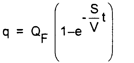
- the part 13 has an internal volume V and is evacuated by a vacuum pump with pumping speed S and if, having a leak, it is sprayed with tracer gas, the gas flow q measured by the spectrometer 15 will follow the relationship : Q F being the final value of the flux.
- V / S ⁇ is homogeneous at one time.
- the processed signal qt is immediately equal to the final value Q F.
- the processed signal q t immediately returns to 0 as soon as the leaking part has been sprayed.
- This output signal q t of the detector of the invention is shown in dotted lines in FIG. 5.
- the pumping speed S is generally known, and we can generally, at least approximately, know the volume V of the part to test.
- V be the volume of enclosure 24 (not including the volume of room 23) and let S be the pumping speed at point 27 and P i the initial air pressure in enclosure 24.
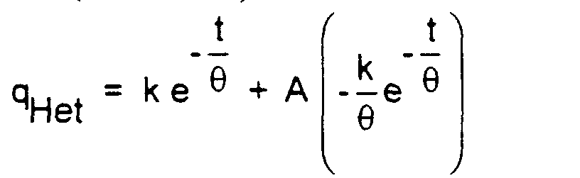
- This background noise is shown in solid lines in FIG. 7 in which the abscissa axis represents time, and the log q He ordinate axis.
- FIG. 9 shows the signal q and the signal q t (logq and logq t ) supplied by the invention at the output of the summator 4.
Landscapes
- Physics & Mathematics (AREA)
- General Physics & Mathematics (AREA)
- Examining Or Testing Airtightness (AREA)
Description

donc


on a : qHet = O

- suppression du bruit de fond dû à l'hélium de l'air de l'enceinte 24,
- apparition immédiate du bruit de fond résiduel final qr,
- apparition, dès l'instant t1 d'injection du gaz traceur (He) dans la pièce à tester 23, du signal final QF = qr + qfuite finale
- un gain de cadence,
- une réduction de la puissance, et donc des coûts des systèmes de pompage,
- une mesure plus fiable,
- la possibilité d'exploiter au maximum les possibilités de test sous vide à haute pression par le fait qu'on élimine le bruit de fond,
- une amélioration du temps de réponse et de la sensibilité en test par reniflage,
- l'extension des capacités de test des détecteurs à de plus gros volumes sans pompage supplémentaire.
Claims (3)
- Détecteur de fuite à gaz traceur comportant un spectromètre de masse (2) fournissant un signal q proportionnel à la pression partielle de gaz traceur dans le spectromètre, caractérisé en ce qu'il comprend en outre des moyens (5, 6) pour obtenir à partir de ce signal q un signal q' = A dq / dt, A étant un coefficient amplificateur réglable et dq / dt la dérivée par rapport au temps du signal q, et des moyens (4) pour obtenir un signal de sortie appelé signal traité qt = q + q'.
- Détecteur de fuite selon la revendication 1 utilisé pour effectuer un test d'étanchéité sur une pièce (13) de volume interne V qui, au moment de la mesure, est relié à une pompe à vide (19 ou 21) du détecteur ayant à l'aspiration une vitesse de pompage S (S2 ou S1), l'aspiration de ladite pompe étant en outre reliée directement, ou par l'intermédiaire d'une ou plusieurs autres pompes en série, audit spectromètre de masse (15), caractérisé en ce que ledit coefficient A est choisi égal à V / S.
- Détecteur de fuite selon la revendication 1 utilisé pour effectuer un test d'étanchéité sur une pièce (23) pressurisée en gaz traceur et placée dans une enceinte étanche (24) de volume interne, hors ladite pièce, égale à V qui, au moment de la mesure, est reliée à une pompe à vide (25) du détecteur ayant à l'aspiration une vitesse de pompage S, l'aspiration de ladite pompe étant en outre reliée, directement ou par l'intermédiaire d'une ou plusieurs autres pompes en série, audit spectromètre de masse (26), caractérisé en ce que ledit coefficient A est choisi égal à V / S.
Applications Claiming Priority (2)
| Application Number | Priority Date | Filing Date | Title |
|---|---|---|---|
| FR9505671A FR2734053B1 (fr) | 1995-05-12 | 1995-05-12 | Detecteur de fuite a gaz traceur |
| FR9505671 | 1995-05-12 |
Publications (2)
| Publication Number | Publication Date |
|---|---|
| EP0742429A1 EP0742429A1 (fr) | 1996-11-13 |
| EP0742429B1 true EP0742429B1 (fr) | 2001-08-08 |
Family
ID=9478937
Family Applications (1)
| Application Number | Title | Priority Date | Filing Date |
|---|---|---|---|
| EP96400965A Expired - Lifetime EP0742429B1 (fr) | 1995-05-12 | 1996-05-06 | Détecteur de fuite à gaz traceur |
Country Status (5)
| Country | Link |
|---|---|
| US (1) | US5681983A (fr) |
| EP (1) | EP0742429B1 (fr) |
| JP (1) | JPH08304218A (fr) |
| DE (1) | DE69614307T2 (fr) |
| FR (1) | FR2734053B1 (fr) |
Cited By (1)
| Publication number | Priority date | Publication date | Assignee | Title |
|---|---|---|---|---|
| CN104931532A (zh) * | 2014-03-18 | 2015-09-23 | 中国科学院高能物理研究所 | 一种用于气体探测器的读出asic芯片以及气体探测器 |
Families Citing this family (16)
| Publication number | Priority date | Publication date | Assignee | Title |
|---|---|---|---|---|
| AU2900399A (en) * | 1998-03-11 | 1999-09-27 | True Technology, Inc. | Method and apparatus for detection of leaks in hermetic packages |
| FR2787192B1 (fr) | 1998-12-10 | 2001-01-05 | Cit Alcatel | Vitesse variable sur le pompage primaire d'un detecteur de fuites par gaz traceur |
| WO2004040256A2 (fr) * | 2002-07-10 | 2004-05-13 | Vista Engineering Technologies L.L.C. | Procede de detection et de caracterisation de contaminants dans des tuyaux et dans des conduits au moyen de traceurs interactifs |
| WO2005081696A2 (fr) * | 2003-10-06 | 2005-09-09 | Vista Engineering Technologies, L.L.C. | Procede et appareil de detection et de localisation de substances explosives, biologiques et chimiques dans des conduites et structures au moyen de traceurs |
| US7168297B2 (en) * | 2003-10-28 | 2007-01-30 | Environmental Systems Products Holdings Inc. | System and method for testing fuel tank integrity |
| DE102004050762A1 (de) * | 2004-10-16 | 2006-04-20 | Inficon Gmbh | Verfahren zur Lecksuche |
| US20110048111A1 (en) * | 2009-08-31 | 2011-03-03 | United Technologies Corporation | Method of leak testing aerospace components |
| EP2686657B1 (fr) * | 2011-03-16 | 2019-11-27 | Norden Machinery Ab | Procédé et ensemble de détection de fuite |
| TWI449907B (zh) * | 2011-12-29 | 2014-08-21 | Ind Tech Res Inst | 氣體洩漏判別方法及系統 |
| US10408763B2 (en) | 2015-01-30 | 2019-09-10 | Mécanique Analytique Inc. | Systems and methods for testing for a gas leak through a gas flow component |
| AU2017268056B2 (en) * | 2016-05-18 | 2021-08-05 | Lineriders Inc. | Apparatus and methodologies for leak detection using gas and infrared thermography |
| FR3068781A1 (fr) | 2017-07-06 | 2019-01-11 | Ateq | Procede de detection de fuite d'une piece creuse et installation pour la mise en œuvre d'un tel procede |
| FR3073288B1 (fr) * | 2017-11-06 | 2019-11-01 | Ateq | Procede de controle de l'etancheite d'un objet a tester par detection d'un gaz traceur par une sonde de reniflage. |
| FR3073623B1 (fr) | 2017-11-16 | 2019-11-08 | Ateq | Installation et procede de detection et de localisation de fuite dans un circuit de transport d'un fluide, notamment d'un aeronef |
| FR3092171B1 (fr) * | 2019-01-29 | 2021-04-30 | Ateq | Système de détection de fuite par gaz traceur et utilisation correspondante. |
| DE102021119302A1 (de) | 2021-07-26 | 2023-01-26 | Inficon Gmbh | Auswertung des Messsignals eines Vakuumlecksuchers |
Family Cites Families (2)
| Publication number | Priority date | Publication date | Assignee | Title |
|---|---|---|---|---|
| CH594239A5 (fr) * | 1975-06-18 | 1977-12-30 | Balzers Patent Beteilig Ag | |
| DE3038089A1 (de) * | 1980-10-09 | 1982-05-19 | Messer Griesheim Gmbh, 6000 Frankfurt | Verfahren zum ermitteln der stationaeren leckrate |
-
1995
- 1995-05-12 FR FR9505671A patent/FR2734053B1/fr not_active Expired - Fee Related
-
1996
- 1996-05-06 DE DE69614307T patent/DE69614307T2/de not_active Expired - Fee Related
- 1996-05-06 EP EP96400965A patent/EP0742429B1/fr not_active Expired - Lifetime
- 1996-05-10 US US08/644,581 patent/US5681983A/en not_active Expired - Fee Related
- 1996-05-10 JP JP8116844A patent/JPH08304218A/ja not_active Withdrawn
Cited By (1)
| Publication number | Priority date | Publication date | Assignee | Title |
|---|---|---|---|---|
| CN104931532A (zh) * | 2014-03-18 | 2015-09-23 | 中国科学院高能物理研究所 | 一种用于气体探测器的读出asic芯片以及气体探测器 |
Also Published As
| Publication number | Publication date |
|---|---|
| JPH08304218A (ja) | 1996-11-22 |
| US5681983A (en) | 1997-10-28 |
| DE69614307D1 (de) | 2001-09-13 |
| EP0742429A1 (fr) | 1996-11-13 |
| DE69614307T2 (de) | 2002-05-02 |
| FR2734053A1 (fr) | 1996-11-15 |
| FR2734053B1 (fr) | 1997-06-13 |
Similar Documents
| Publication | Publication Date | Title |
|---|---|---|
| EP0742429A1 (fr) | Détecteur de fuite à gaz traceur | |
| EP0268777B1 (fr) | Installation de fuite à gaz traceur et procédé d'utilisation | |
| EP0534825B1 (fr) | Détecteur de fuite à hélium | |
| JPH0478936B2 (fr) | ||
| EP0869344B1 (fr) | Détecteur de fuite à gaz traceur | |
| EP0464292B1 (fr) | Ensemble mécanique de pompage pour vide secondaire et installation de détection de fuite utilisant un tel ensemble | |
| FR3072774A1 (fr) | Detecteur de fuites pour le controle de l'etancheite d'un objet a tester | |
| EP0475246B1 (fr) | Détecteur de fuite haut flux à trois filtres moléculaires | |
| FR2921488A1 (fr) | Dispositif et procede pour la detection de fuites a haute pression pr gaz traceur dans une piece a tester. | |
| FR2653558A1 (fr) | Systeme de detection de fuites a gaz traceur. | |
| EP1008841B1 (fr) | Vitesse variable sur le pompage primaire d'un détecteur de fuites par gaz traceur | |
| CA2045046A1 (fr) | Dispositif de mesure de l'effet multipactor par bruit de phase | |
| FR3121749A1 (fr) | Système de détection de fuites perfectionné par reniflage | |
| EP0716296B1 (fr) | Détecteur de fuite | |
| EP1942327B1 (fr) | Dispositif et procédé de détection rapide de fuites | |
| CA2034143A1 (fr) | Installation de detection de fuite a pompe holweck a prise intermediaire | |
| EP3795972B1 (fr) | Module de détection de fuites et procédé de contrôle de l'étanchéité d'un objet à tester par gaz traceur | |
| FR3136551A1 (fr) | Installation de détection de fuites et procédé de contrôle de l’étanchéité | |
| FR3121750A1 (fr) | Système de détection de fuites perfectionné par aspersion | |
| JP3371924B2 (ja) | 逆拡散測定によるヘリウムリーク量検出方法 | |
| EP0288339B1 (fr) | Procédé pour tester l'étanchéité d'une cavité | |
| FR3073288B1 (fr) | Procede de controle de l'etancheite d'un objet a tester par detection d'un gaz traceur par une sonde de reniflage. | |
| WO2026046641A1 (fr) | Procédé de contrôle de dérive d'un détecteur de fuites et équipement associé | |
| FR3154804A1 (fr) | Ensemble de détection de fuites | |
| EP0753731A1 (fr) | Procédé de contrÔle d'un débit de fuite et application du procédé à la mesure du taux de gaz dans un liquide |
Legal Events
| Date | Code | Title | Description |
|---|---|---|---|
| PUAI | Public reference made under article 153(3) epc to a published international application that has entered the european phase |
Free format text: ORIGINAL CODE: 0009012 |
|
| AK | Designated contracting states |
Kind code of ref document: A1 Designated state(s): CH DE GB IT LI |
|
| 17P | Request for examination filed |
Effective date: 19970513 |
|
| GRAG | Despatch of communication of intention to grant |
Free format text: ORIGINAL CODE: EPIDOS AGRA |
|
| 17Q | First examination report despatched |
Effective date: 20000810 |
|
| GRAG | Despatch of communication of intention to grant |
Free format text: ORIGINAL CODE: EPIDOS AGRA |
|
| GRAH | Despatch of communication of intention to grant a patent |
Free format text: ORIGINAL CODE: EPIDOS IGRA |
|
| GRAH | Despatch of communication of intention to grant a patent |
Free format text: ORIGINAL CODE: EPIDOS IGRA |
|
| RAP1 | Party data changed (applicant data changed or rights of an application transferred) |
Owner name: ALCATEL |
|
| GRAA | (expected) grant |
Free format text: ORIGINAL CODE: 0009210 |
|
| AK | Designated contracting states |
Kind code of ref document: B1 Designated state(s): CH DE GB IT LI |
|
| REG | Reference to a national code |
Ref country code: CH Ref legal event code: EP |
|
| GBT | Gb: translation of ep patent filed (gb section 77(6)(a)/1977) |
Effective date: 20010808 |
|
| REG | Reference to a national code |
Ref country code: CH Ref legal event code: NV Representative=s name: CABINET ROLAND NITHARDT CONSEILS EN PROPRIETE INDU |
|
| REF | Corresponds to: |
Ref document number: 69614307 Country of ref document: DE Date of ref document: 20010913 |
|
| REG | Reference to a national code |
Ref country code: GB Ref legal event code: IF02 |
|
| PLBE | No opposition filed within time limit |
Free format text: ORIGINAL CODE: 0009261 |
|
| STAA | Information on the status of an ep patent application or granted ep patent |
Free format text: STATUS: NO OPPOSITION FILED WITHIN TIME LIMIT |
|
| 26N | No opposition filed |
Opponent name: KONINKLIJKE PHILIPS ELECTRONICS N.V. |
|
| PGFP | Annual fee paid to national office [announced via postgrant information from national office to epo] |
Ref country code: CH Payment date: 20030422 Year of fee payment: 8 |
|
| PGFP | Annual fee paid to national office [announced via postgrant information from national office to epo] |
Ref country code: DE Payment date: 20030514 Year of fee payment: 8 |
|
| PGFP | Annual fee paid to national office [announced via postgrant information from national office to epo] |
Ref country code: GB Payment date: 20040504 Year of fee payment: 9 |
|
| PG25 | Lapsed in a contracting state [announced via postgrant information from national office to epo] |
Ref country code: LI Free format text: LAPSE BECAUSE OF NON-PAYMENT OF DUE FEES Effective date: 20040531 Ref country code: CH Free format text: LAPSE BECAUSE OF NON-PAYMENT OF DUE FEES Effective date: 20040531 |
|
| PG25 | Lapsed in a contracting state [announced via postgrant information from national office to epo] |
Ref country code: DE Free format text: LAPSE BECAUSE OF NON-PAYMENT OF DUE FEES Effective date: 20041201 |
|
| REG | Reference to a national code |
Ref country code: CH Ref legal event code: PL |
|
| PG25 | Lapsed in a contracting state [announced via postgrant information from national office to epo] |
Ref country code: IT Free format text: LAPSE BECAUSE OF NON-PAYMENT OF DUE FEES Effective date: 20050506 Ref country code: GB Free format text: LAPSE BECAUSE OF NON-PAYMENT OF DUE FEES Effective date: 20050506 |
|
| GBPC | Gb: european patent ceased through non-payment of renewal fee |
Effective date: 20050506 |