EP0741631B1 - Positive radial location of wheels on spindles - Google Patents
Positive radial location of wheels on spindles Download PDFInfo
- Publication number
- EP0741631B1 EP0741631B1 EP95906427A EP95906427A EP0741631B1 EP 0741631 B1 EP0741631 B1 EP 0741631B1 EP 95906427 A EP95906427 A EP 95906427A EP 95906427 A EP95906427 A EP 95906427A EP 0741631 B1 EP0741631 B1 EP 0741631B1
- Authority
- EP
- European Patent Office
- Prior art keywords
- wheel
- spindle
- flange
- balls
- ball race
- Prior art date
- Legal status (The legal status is an assumption and is not a legal conclusion. Google has not performed a legal analysis and makes no representation as to the accuracy of the status listed.)
- Expired - Lifetime
Links
Images


Classifications
-
- F—MECHANICAL ENGINEERING; LIGHTING; HEATING; WEAPONS; BLASTING
- F16—ENGINEERING ELEMENTS AND UNITS; GENERAL MEASURES FOR PRODUCING AND MAINTAINING EFFECTIVE FUNCTIONING OF MACHINES OR INSTALLATIONS; THERMAL INSULATION IN GENERAL
- F16D—COUPLINGS FOR TRANSMITTING ROTATION; CLUTCHES; BRAKES
- F16D1/00—Couplings for rigidly connecting two coaxial shafts or other movable machine elements
- F16D1/06—Couplings for rigidly connecting two coaxial shafts or other movable machine elements for attachment of a member on a shaft or on a shaft-end
- F16D1/08—Couplings for rigidly connecting two coaxial shafts or other movable machine elements for attachment of a member on a shaft or on a shaft-end with clamping hub; with hub and longitudinal key
- F16D1/0829—Couplings for rigidly connecting two coaxial shafts or other movable machine elements for attachment of a member on a shaft or on a shaft-end with clamping hub; with hub and longitudinal key with radial loading of both hub and shaft by an intermediate ring or sleeve
-
- B—PERFORMING OPERATIONS; TRANSPORTING
- B24—GRINDING; POLISHING
- B24B—MACHINES, DEVICES, OR PROCESSES FOR GRINDING OR POLISHING; DRESSING OR CONDITIONING OF ABRADING SURFACES; FEEDING OF GRINDING, POLISHING, OR LAPPING AGENTS
- B24B45/00—Means for securing grinding wheels on rotary arbors
-
- B—PERFORMING OPERATIONS; TRANSPORTING
- B24—GRINDING; POLISHING
- B24D—TOOLS FOR GRINDING, BUFFING OR SHARPENING
- B24D5/00—Bonded abrasive wheels, or wheels with inserted abrasive blocks, designed for acting only by their periphery; Bushings or mountings therefor
- B24D5/16—Bushings; Mountings
-
- F—MECHANICAL ENGINEERING; LIGHTING; HEATING; WEAPONS; BLASTING
- F16—ENGINEERING ELEMENTS AND UNITS; GENERAL MEASURES FOR PRODUCING AND MAINTAINING EFFECTIVE FUNCTIONING OF MACHINES OR INSTALLATIONS; THERMAL INSULATION IN GENERAL
- F16D—COUPLINGS FOR TRANSMITTING ROTATION; CLUTCHES; BRAKES
- F16D1/00—Couplings for rigidly connecting two coaxial shafts or other movable machine elements
- F16D1/06—Couplings for rigidly connecting two coaxial shafts or other movable machine elements for attachment of a member on a shaft or on a shaft-end
- F16D1/076—Couplings for rigidly connecting two coaxial shafts or other movable machine elements for attachment of a member on a shaft or on a shaft-end by clamping together two faces perpendicular to the axis of rotation, e.g. with bolted flanges
-
- F—MECHANICAL ENGINEERING; LIGHTING; HEATING; WEAPONS; BLASTING
- F16—ENGINEERING ELEMENTS AND UNITS; GENERAL MEASURES FOR PRODUCING AND MAINTAINING EFFECTIVE FUNCTIONING OF MACHINES OR INSTALLATIONS; THERMAL INSULATION IN GENERAL
- F16D—COUPLINGS FOR TRANSMITTING ROTATION; CLUTCHES; BRAKES
- F16D1/00—Couplings for rigidly connecting two coaxial shafts or other movable machine elements
- F16D1/06—Couplings for rigidly connecting two coaxial shafts or other movable machine elements for attachment of a member on a shaft or on a shaft-end
- F16D1/08—Couplings for rigidly connecting two coaxial shafts or other movable machine elements for attachment of a member on a shaft or on a shaft-end with clamping hub; with hub and longitudinal key
- F16D1/09—Couplings for rigidly connecting two coaxial shafts or other movable machine elements for attachment of a member on a shaft or on a shaft-end with clamping hub; with hub and longitudinal key with radial clamping due to axial loading of at least one pair of conical surfaces
-
- F—MECHANICAL ENGINEERING; LIGHTING; HEATING; WEAPONS; BLASTING
- F16—ENGINEERING ELEMENTS AND UNITS; GENERAL MEASURES FOR PRODUCING AND MAINTAINING EFFECTIVE FUNCTIONING OF MACHINES OR INSTALLATIONS; THERMAL INSULATION IN GENERAL
- F16D—COUPLINGS FOR TRANSMITTING ROTATION; CLUTCHES; BRAKES
- F16D1/00—Couplings for rigidly connecting two coaxial shafts or other movable machine elements
- F16D1/06—Couplings for rigidly connecting two coaxial shafts or other movable machine elements for attachment of a member on a shaft or on a shaft-end
- F16D1/08—Couplings for rigidly connecting two coaxial shafts or other movable machine elements for attachment of a member on a shaft or on a shaft-end with clamping hub; with hub and longitudinal key
- F16D1/09—Couplings for rigidly connecting two coaxial shafts or other movable machine elements for attachment of a member on a shaft or on a shaft-end with clamping hub; with hub and longitudinal key with radial clamping due to axial loading of at least one pair of conical surfaces
- F16D1/092—Couplings for rigidly connecting two coaxial shafts or other movable machine elements for attachment of a member on a shaft or on a shaft-end with clamping hub; with hub and longitudinal key with radial clamping due to axial loading of at least one pair of conical surfaces the pair of conical mating surfaces being provided on the coupled hub and shaft
Definitions
- This invention relates to a method of and an apparatus for effecting the positive radial location of wheels on spindles, more especially the location of grinding wheels, for example diamond and cubic boron nitride (CBN) grinding wheels, on the spindle of a grinding machine.
- grinding wheels for example diamond and cubic boron nitride (CBN) grinding wheels
- the progressive movement of the wheel towards the flange serves to centre the wheel on the spindle axis to an accuracy determined by the identity of the diameters of the balls forming the ball race. Since these can be manufactured to a very high tolerance, the invention allows a very simple and accurate centering of the wheel on the spindle.
- apparatus for mounting a wheel on a spindle for effecting positive radial, centralised location thereon, as per independent claim 2.
- the balls of the ball race are closely matched for diameter and roundness to provide the correct outside diameter for the ball race, such that in the fully tightened condition there is an interference fit between the wheel and the balls and the spindle.
- the balls roll into the positions appropriate to a true centering of the wheel on the spindle, and, together with the hardened surfaces, act to absorb interference.
- the trueness of the fit of the wheel is affected only by the tolerance in manufacture of the wheel and the tolerance of the ball diameter.
- the invention specifically enables the mounting of grinding wheels, for example diamond and CBN grinding wheels, on the spindles of grinding machines.
- the invention optionally lies in a grinding machine having a drive spindle for a grinding wheel and means for attaching the grinding wheel thereto as provided by the invention.
- a grinding machine drive spindle 10 includes a radial flange 12 to provide an axial stop for a grinding wheel when fitted on the spindle, and a reduced diameter end 14 beyond the flange, for receiving the wheel.
- the surface 16 of the spindle end 14 is surface hardened.
- a ball cage 18 for retaining a plurality of balls 20 to form a ball race circularly around the spindle end 14.
- balls 20 there are 36 balls in the race and they are formed from hardened steel.
- the internal surface 28 of the central aperture of the grinding wheel 26 tapers axially from an entrance 30 in one face of the wheel and is surface hardened to provide the external running surface for the ball race 20. Axially beyond the entrance region 30 the internal surface of the central aperture is cylindrical. A clamping plate 32 is forced in an axial direction by tightening centre bolt 34 so as to clamp the grinding wheel 26 between the plate 32 and the flange 12.
- the balls 20 automatically centre the wheel on the spindle and the wheel is forced thereover, the tapered opening 30 facilitating the introduction of the wheel over the ball race and the cylindrical region of the internal aperture of the wheel producing a zero clearance, low interference fit between the balls 20 and the hardened surface 28, interference being absorbed as the wheel 26 is drawn into its final clamped position.
- the wheel 26 is shown clamped against the flange 12 in the upper part of the figure.
- the balls 20 are carefully matched as regards size, so that the outside diameter of the balls is "identical" to within a very small tolerance.
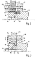
- FIG. 2 A modified arrangement is shown in Figure 2 in which similar reference numerals have been employed to indicate similar parts.
- balls 20 are retained in place by a retaining ring 36, which is secured to the spindle 10 by bolt 38.
- An outer ring 40 can be tightened in a similar manner to item 32, to force the balls into position, using bolts 42, there being a number of such bolts equally angularly spaced around the ring 40.
- the trueing effect produced during tightening is similar to that described with reference to Figure 1, and preferably the bolts 42 are tightened progressively, working around the ring.
- the Figure 1 arrangement has the advantage of single point tightening.
- the arrangements of Figures 2 also require exactly matched balls, selected as to size and roundness, to provide the appropriate and correct outside diameter of the ball race to achieve the accurate centering of the wheel on the spindle.
- a machine spindle 66 similarly has a flange 68 and a reduced diameter end 70 which is surface hardened to provide a very hard circumferential surface 72.
- a ball race comprising a cage 74 containing 36 balls 76.
- the assembly is shown in its unclamped condition in the lower part of Figure 4 and in its clamped condition in the upper part of the figure.
- the ball cage 74 retains the balls 76 in position so as to centre the grinding wheel 78.
- the latter is sleeved internally with a hardened ring 79 typically of hardened steel or the like.
- a central bolt 80 allows plate 82 to be clamped directly onto the grinding wheel 78. As the grinding wheel 78 is shifted to the right by turning the bolt 80, the balls 76 are also forced to the right against springs such as 84. As previously described, this centres the grinding wheel 78 about the spindle 66.
- Drive pins 86 extend between the wheel and the flange to transmit drive between the flange and the grinding wheel 78.
- Seals 88, 90 are provided to seal the gap between the ball cage 74 and the grinding wheel 78 and any gap between the grinding wheel 78 and the flange 68.
- the seals 88, 90 prevent the entry of coolant and/or dirt into the space containing the balls 76. This protects the balls and extends the life of the ball race.
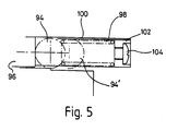
- FIG. 5 is an enlarged detail of the area 92 in Figure 4.
- Each ball 94 is moveable between its position shown by 94 and that denoted by 94'. Tightening of the bolt 80 as shown in Figure 4, causes axial movement of the ball cage 96 so as to move the balls from their unclamped condition 94 to their clamped position at 94'.
- Springs 98 locate the balls 94 within the slots 100 and a cylindrical end stop 102 and screw 104 serve to retain the balls and springs in their slots.
- the inner end of the hardened steel ring 79 may be tapered or simply formed with an enlarged diameter region as shown simply to facilitate the fitting of the ring over the ball race.
- the action of tightening the clamping plate 82 first of all forces the balls against their springs and then creates an interference fit as the balls are forced into the smaller diameter cylindrical region of the ring 79 to lie between the two cylindrical surfaces of the ring 79 and the spindle end.
Landscapes
- Engineering & Computer Science (AREA)
- General Engineering & Computer Science (AREA)
- Mechanical Engineering (AREA)
- Constituent Portions Of Griding Lathes, Driving, Sensing And Control (AREA)
- Rolling Contact Bearings (AREA)
- Grinding Of Cylindrical And Plane Surfaces (AREA)
Description
Claims (17)
- A method of mounting a wheel (26) on a drive spindle (10) so as to achieve positive radial centralised location of the wheel thereon, according to which the spindle is provided with a flange (12) adjacent a surface hardened end region (14) thereof over which a central aperture (28) of the wheel will fit, comprising the step of mounting a ball race (18) of closely matched balls (20) over the spindle near to the flange, characterised by the step of axially displacing the wheel towards the flange so as to progressively squeeze a cylindrical non-tapered region of the wheel aperture (28) over the ball race to create an all-round interference fit between the wheel and the balls and the balls and the end region of the spindle, the progressive movement of the wheel towards the flange serving to centre the wheel on the spindle (10), wherein the wheel aperture is tapered (30) so as to facilitate the fitting of the wheel to the spindle.
- Apparatus for mounting a wheel (26) on a spindle (10) for effecting positive radial, centralised location thereon, comprising spindle with a flange (12) against which the wheel can be axially located, a ball race (18) of closely matched balls (20) around the spindle on the same side of the flange as the wheel, characterised by a tapered aperture (30) in the wheel to allow it to be pushed over the ball race, and axial drive means including a thrust plate (32) for axially displacing the wheel relative to the spindle so as to progressively squeeze a cylindrical non-tapered region of the wheel aperture over the ball race into an all-round interference fit with the spindle and into contact with the flange.
- Apparatus according to claim 2, wherein the aperture (30) in the wheel is enlarged at the end which opens onto the face which is to contact the flange (12), to facilitate the fitting of the wheel (26) to the ball race (18), the remainder of the aperture in the wheel being of a cylindrical section (28).
- Apparatus according to claim 2 or claim 3, wherein the thrust plate (32) serves to force the ball race (18) as well as the wheel (26) in an axial sense towards the flange (12).
- Apparatus according to claim 2 or claim 3, wherein the drive means comprises a first thrust plate (36) to act on the ball race and a second thrust plate (40) to act on the wheel (26), the two thrust plates being independently movable to effect their respective clamping.
- Apparatus according to any one of claims 2 to 5, wherein the aperture in the wheel tapers from an enlarged end (30) towards a cylindrical section (28).
- Apparatus according to any one of claims 2 to 5, wherein a step is formed between the enlarged end and the cylindrical section which is to form the interference fit with the ball race, the step itself being tapered to facilitate the forcing of the balls into the cylindrical section.
- Apparatus according to any one of claims 2 to 7, wherein the opposed faces of the wheel aperture and the spindle are surface hardened to provide resistance to wear.
- Apparatus according to any one of claims 2 to 8, wherein the drive means includes bolt means (34) for clamping the parts together and which acts directly between a clamping plate (32) and the spindle end (14).
- Apparatus according to any one of claims 2 to 8, wherein first bolt means (38) serves to clamp a first ring member (36) in place to retain the balls (20) in position, and a second ring member (40) and associated bolt means (42) serve to clamp the wheel (26) to the flange (10).
- Apparatus according to any one of claims 2 to 8, wherein a first bolt means (62) serves to clamp a ball race end closure to the spindle end (48) and a second bolt means (42) serves to secure a thrust plate (40) to the spindle end which, upon being tightened towards the spindle end, engages the end face of the wheel (54) and forces the wheel axially so as to engage the ball race and finally become clamped against the flange (46).
- Apparatus according to any one of claims 2 to 11, wherein an end clamping plate (32) is employed to clamp the wheel (26) against the flange and the interference fit between the clamping plate and the flange is sufficient to transmit drive to the wheel.
- Apparatus according to any one of claims 2 to 11, wherein drive pins (86) extend between the wheel and the flange.
- Apparatus according to any of claims 2 to 13, wherein the balls are retained in a cage (74) or are retained in the spindle end in axial or radial grooves with reduced width openings to prevent the balls from leaving radially.
- Apparatus according to claim 19, wherein the balls are resiliently urged axially by springs (84) in an opposite sense to the direction in which the tightening will cause them to move.
- Apparatus according to any one of claims 2 to 15, wherein the wheel is a grinding wheel.
- A grinding machine having a drive spindle for a grinding wheel and means for attaching the grinding wheel thereto according to any one of claims 2 to 15.
Priority Applications (1)
| Application Number | Priority Date | Filing Date | Title |
|---|---|---|---|
| EP98100761A EP0849042A1 (en) | 1994-01-25 | 1995-01-25 | Positive radial location of wheels on spindles |
Applications Claiming Priority (3)
| Application Number | Priority Date | Filing Date | Title |
|---|---|---|---|
| GB9401395 | 1994-01-25 | ||
| GB9401395A GB9401395D0 (en) | 1994-01-25 | 1994-01-25 | Positive radial location of wheels on shafts |
| PCT/GB1995/000147 WO1995019870A1 (en) | 1994-01-25 | 1995-01-25 | Positive radial location of wheels on spindles |
Related Child Applications (1)
| Application Number | Title | Priority Date | Filing Date |
|---|---|---|---|
| EP98100761A Division EP0849042A1 (en) | 1994-01-25 | 1995-01-25 | Positive radial location of wheels on spindles |
Publications (2)
| Publication Number | Publication Date |
|---|---|
| EP0741631A1 EP0741631A1 (en) | 1996-11-13 |
| EP0741631B1 true EP0741631B1 (en) | 1999-04-28 |
Family
ID=10749286
Family Applications (2)
| Application Number | Title | Priority Date | Filing Date |
|---|---|---|---|
| EP95906427A Expired - Lifetime EP0741631B1 (en) | 1994-01-25 | 1995-01-25 | Positive radial location of wheels on spindles |
| EP98100761A Withdrawn EP0849042A1 (en) | 1994-01-25 | 1995-01-25 | Positive radial location of wheels on spindles |
Family Applications After (1)
| Application Number | Title | Priority Date | Filing Date |
|---|---|---|---|
| EP98100761A Withdrawn EP0849042A1 (en) | 1994-01-25 | 1995-01-25 | Positive radial location of wheels on spindles |
Country Status (6)
| Country | Link |
|---|---|
| EP (2) | EP0741631B1 (en) |
| AU (1) | AU1462395A (en) |
| DE (1) | DE69509364T2 (en) |
| ES (1) | ES2132627T3 (en) |
| GB (2) | GB9401395D0 (en) |
| WO (1) | WO1995019870A1 (en) |
Families Citing this family (3)
| Publication number | Priority date | Publication date | Assignee | Title |
|---|---|---|---|---|
| DE19650623A1 (en) * | 1996-12-06 | 1998-06-18 | Naxos Union Schleifmittel | Tool holder on machine-tool spindle |
| US6277012B1 (en) * | 1998-01-14 | 2001-08-21 | Norton Company | Disk locking device |
| CN104191368B (en) * | 2014-09-05 | 2016-08-17 | 郑州磨料磨具磨削研究所有限公司 | A kind of method of point contact type fine adjustment emery wheel and mechanism |
Family Cites Families (4)
| Publication number | Priority date | Publication date | Assignee | Title |
|---|---|---|---|---|
| GB633169A (en) * | 1946-08-09 | 1949-12-12 | Hugo Allemann | An improved rotary arbor to which a grinding wheel is fixed |
| GB667627A (en) * | 1949-03-04 | 1952-03-05 | Philips Electrical Ind Ltd | Improvements in or relating to mechanical joints |
| AT357843B (en) * | 1978-11-23 | 1980-08-11 | Linsinger Ernst Dipl Ing Dr | QUICK CLAMPING DEVICE FOR FASTENING ROTATING TOOLS ON THE SPINDLE OF A MACHINE TOOL |
| DE3823591A1 (en) * | 1987-12-23 | 1989-07-06 | Fortuna Werke Maschf Ag | GRINDING WHEEL |
-
1994
- 1994-01-25 GB GB9401395A patent/GB9401395D0/en active Pending
-
1995
- 1995-01-25 DE DE69509364T patent/DE69509364T2/en not_active Expired - Fee Related
- 1995-01-25 EP EP95906427A patent/EP0741631B1/en not_active Expired - Lifetime
- 1995-01-25 EP EP98100761A patent/EP0849042A1/en not_active Withdrawn
- 1995-01-25 AU AU14623/95A patent/AU1462395A/en not_active Abandoned
- 1995-01-25 WO PCT/GB1995/000147 patent/WO1995019870A1/en not_active Ceased
- 1995-01-25 ES ES95906427T patent/ES2132627T3/en not_active Expired - Lifetime
- 1995-01-25 GB GB9501414A patent/GB2285846B/en not_active Expired - Fee Related
Also Published As
| Publication number | Publication date |
|---|---|
| EP0849042A1 (en) | 1998-06-24 |
| AU1462395A (en) | 1995-08-08 |
| DE69509364D1 (en) | 1999-06-02 |
| ES2132627T3 (en) | 1999-08-16 |
| EP0741631A1 (en) | 1996-11-13 |
| DE69509364T2 (en) | 1999-08-26 |
| GB2285846A (en) | 1995-07-26 |
| WO1995019870A1 (en) | 1995-07-27 |
| GB9401395D0 (en) | 1994-03-23 |
| GB9501414D0 (en) | 1995-03-15 |
| GB2285846B (en) | 1998-02-25 |
Similar Documents
| Publication | Publication Date | Title |
|---|---|---|
| EP2563639B1 (en) | Apparatus for final finishing a wheel hub of a knuckle assembly and related method | |
| EP1736326B1 (en) | Bearing unit for wheel and manufacturing method thereof | |
| EP0857880B1 (en) | Method of processing a shaft for hub unit | |
| US5937499A (en) | Machining brake disc without moment load on bearing | |
| US9839962B2 (en) | Processing method for brake rotor-equipped wheel bearing devices | |
| EP1196261B1 (en) | A method of machining a hub bearing unit for a wheel of a motor vehicle | |
| US5915502A (en) | Brake disc assembly and a method for fabricating brake disc | |
| US20060110087A1 (en) | Bearing unit for wheel and method of fabricating the same | |
| CN108381340A (en) | A kind of asymmetric connecting shaft combination bearing, mill machining tool, mill processing method | |
| US7650696B2 (en) | Manufacturing method for bearing unit for support wheel | |
| US8109578B2 (en) | Hub wheel, hub unit, and method of working hub wheel | |
| US6062737A (en) | Wheel hub retention apparatus | |
| EP0849042A1 (en) | Positive radial location of wheels on spindles | |
| US3665657A (en) | Apparatus for mounting disc brake rotors during truing | |
| CN110773759B (en) | Connecting disc subassembly and have its numerical control lathe electricity main shaft | |
| US3623742A (en) | Jaw chuck | |
| CN210879219U (en) | Grinding machine is with preventing spheroid location frock with adjustable crushing wound | |
| CN208409491U (en) | A kind of asymmetric connecting shaft combination bearing, mill machining tool | |
| US7117600B1 (en) | Process of manufacturing a corner assembly | |
| US4726214A (en) | Shrink forming apparatus | |
| KR20200022763A (en) | A machining apparatus for rotating a housing to machine a hub of a hub bearing | |
| JP2003240029A (en) | Wheel bearing unit and manufacturing method thereof | |
| JP2000033564A (en) | Spindle fitting device of rotary grinding wheel |
Legal Events
| Date | Code | Title | Description |
|---|---|---|---|
| PUAI | Public reference made under article 153(3) epc to a published international application that has entered the european phase |
Free format text: ORIGINAL CODE: 0009012 |
|
| 17P | Request for examination filed |
Effective date: 19960321 |
|
| AK | Designated contracting states |
Kind code of ref document: A1 Designated state(s): DE ES FR IT |
|
| 17Q | First examination report despatched |
Effective date: 19970523 |
|
| GRAG | Despatch of communication of intention to grant |
Free format text: ORIGINAL CODE: EPIDOS AGRA |
|
| GRAG | Despatch of communication of intention to grant |
Free format text: ORIGINAL CODE: EPIDOS AGRA |
|
| GRAH | Despatch of communication of intention to grant a patent |
Free format text: ORIGINAL CODE: EPIDOS IGRA |
|
| RAP1 | Party data changed (applicant data changed or rights of an application transferred) |
Owner name: UNOVA U.K. LIMITED |
|
| GRAH | Despatch of communication of intention to grant a patent |
Free format text: ORIGINAL CODE: EPIDOS IGRA |
|
| ITF | It: translation for a ep patent filed | ||
| GRAA | (expected) grant |
Free format text: ORIGINAL CODE: 0009210 |
|
| AK | Designated contracting states |
Kind code of ref document: B1 Designated state(s): DE ES FR IT |
|
| REF | Corresponds to: |
Ref document number: 69509364 Country of ref document: DE Date of ref document: 19990602 |
|
| REG | Reference to a national code |
Ref country code: ES Ref legal event code: FG2A Ref document number: 2132627 Country of ref document: ES Kind code of ref document: T3 |
|
| ET | Fr: translation filed | ||
| PLBE | No opposition filed within time limit |
Free format text: ORIGINAL CODE: 0009261 |
|
| STAA | Information on the status of an ep patent application or granted ep patent |
Free format text: STATUS: NO OPPOSITION FILED WITHIN TIME LIMIT |
|
| 26N | No opposition filed | ||
| PGFP | Annual fee paid to national office [announced via postgrant information from national office to epo] |
Ref country code: FR Payment date: 20060117 Year of fee payment: 12 |
|
| PGFP | Annual fee paid to national office [announced via postgrant information from national office to epo] |
Ref country code: ES Payment date: 20060126 Year of fee payment: 12 |
|
| PGFP | Annual fee paid to national office [announced via postgrant information from national office to epo] |
Ref country code: IT Payment date: 20060131 Year of fee payment: 12 |
|
| PGFP | Annual fee paid to national office [announced via postgrant information from national office to epo] |
Ref country code: DE Payment date: 20060228 Year of fee payment: 12 |
|
| REG | Reference to a national code |
Ref country code: FR Ref legal event code: TP |
|
| PG25 | Lapsed in a contracting state [announced via postgrant information from national office to epo] |
Ref country code: DE Free format text: LAPSE BECAUSE OF NON-PAYMENT OF DUE FEES Effective date: 20070801 |
|
| REG | Reference to a national code |
Ref country code: ES Ref legal event code: PC2A |
|
| REG | Reference to a national code |
Ref country code: FR Ref legal event code: ST Effective date: 20070930 |
|
| REG | Reference to a national code |
Ref country code: ES Ref legal event code: FD2A Effective date: 20070126 |
|
| PG25 | Lapsed in a contracting state [announced via postgrant information from national office to epo] |
Ref country code: FR Free format text: LAPSE BECAUSE OF NON-PAYMENT OF DUE FEES Effective date: 20070131 |
|
| PG25 | Lapsed in a contracting state [announced via postgrant information from national office to epo] |
Ref country code: ES Free format text: LAPSE BECAUSE OF NON-PAYMENT OF DUE FEES Effective date: 20070126 |
|
| PG25 | Lapsed in a contracting state [announced via postgrant information from national office to epo] |
Ref country code: IT Free format text: LAPSE BECAUSE OF NON-PAYMENT OF DUE FEES Effective date: 20070125 |