EP0740944A2 - Halteelement für Defibrillatorelektroden unter Verwendung von Drehzapfen - Google Patents
Halteelement für Defibrillatorelektroden unter Verwendung von Drehzapfen Download PDFInfo
- Publication number
- EP0740944A2 EP0740944A2 EP96302194A EP96302194A EP0740944A2 EP 0740944 A2 EP0740944 A2 EP 0740944A2 EP 96302194 A EP96302194 A EP 96302194A EP 96302194 A EP96302194 A EP 96302194A EP 0740944 A2 EP0740944 A2 EP 0740944A2
- Authority
- EP
- European Patent Office
- Prior art keywords
- retainer assembly
- back plate
- paddle
- back wall
- tool
- Prior art date
- Legal status (The legal status is an assumption and is not a legal conclusion. Google has not performed a legal analysis and makes no representation as to the accuracy of the status listed.)
- Granted
Links
Images



Classifications
-
- B—PERFORMING OPERATIONS; TRANSPORTING
- B25—HAND TOOLS; PORTABLE POWER-DRIVEN TOOLS; MANIPULATORS
- B25H—WORKSHOP EQUIPMENT, e.g. FOR MARKING-OUT WORK; STORAGE MEANS FOR WORKSHOPS
- B25H3/00—Storage means or arrangements for workshops facilitating access to, or handling of, work tools or instruments
- B25H3/006—Storage means specially adapted for one specific hand apparatus, e.g. an electric drill
-
- A—HUMAN NECESSITIES
- A61—MEDICAL OR VETERINARY SCIENCE; HYGIENE
- A61N—ELECTROTHERAPY; MAGNETOTHERAPY; RADIATION THERAPY; ULTRASOUND THERAPY
- A61N1/00—Electrotherapy; Circuits therefor
- A61N1/18—Applying electric currents by contact electrodes
- A61N1/32—Applying electric currents by contact electrodes alternating or intermittent currents
- A61N1/38—Applying electric currents by contact electrodes alternating or intermittent currents for producing shock effects
- A61N1/39—Heart defibrillators
- A61N1/3904—External heart defibrillators [EHD]
Definitions
- This invention relates in general to holders for retaining hand-held devices. Particularly, this invention is a retainer for holding a defibrillator paddle.
- a defibrillator is a device for applying an electrical shock to the chest area of a human to initiate heart beat.
- Defibrillators have electronic circuitry within a housing and two paddles connected by electrical cords. The paddles are retained in pockets on the housing by mechanisms which allow fast and easy withdrawal because the paddles are often used under emergency conditions.
- Defibrillators may either be mounted to a cart or they may be of a hand carried type.
- a typical prior art defibrillator paddle pocket has a back wall with a pair of parallel retainer brackets for receiving a portion of the paddle base.
- a spring engages the base, pressing it against the retainer plates to frictionally hold the paddle in the slot.
- the paddle is removed by a straight outward pull parallel to the back wall.
- the spring is sized so that the retention force is not very high, and preferably equal to the force required to withdraw the paddle.
- the withdrawal force In the case of a hand carried defibrillator, the withdrawal force must be less than the weight of the defibrillator to prevent picking up the entire product when the paddles are removed. Keeping the withdrawal force low has forced the retention force to also be low. This prevents the paddles from being securely retained. This is especially a problem in environments where defibrillators have to be hand carried. Paddles which are not securely retained can easily fall out as the defibrillator is jostled during transport.
- a defibrillator paddle retainer assembly has a resilient retainer back plate that is pivotally secured to the back wall of the pocket.
- a pair of brackets are located on the back plate, defining a slot for receiving an edge of the base of the defibrillator paddle.
- a lip is also located on the retainer back plate for snapping over an opposite edge of the paddle base to retain the paddle in the slot.
- a pull of sufficient force in the withdrawal direction on the handle causes the retainer back plate to resiliently flex.
- the portion of the retainer containing the brackets moves away from the back wall in one direction while the lip is forced in the opposite direction, rotating about the pivot point. This releases the lip from engagement with the edge of the paddle base, allowing the paddle to be removed.
- the retainer assembly provides a low withdrawal force and a high retention force for the paddles.
- Figure 1 is a perspective view illustrating a prior art defibrillator.
- Figure 2 is a partial sectional view of the defibrillator of Figure 1 taken along the line 2-2 of Figure 1.
- Figure 3 is a perspective view of a defibrillator paddle retainer assembly of the preferred embodiment of the invention.
- Figure 4 is a front elevational view of the retainer assembly of Figure 3.
- Figure 5 is an exploded perspective view of the retainer assembly of Figure 3.
- Figure 6 is a perspective view of the retainer assembly of Figure 3 and showing a defibrillator paddle located therein.
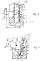
- Figure 7 is a sectional view of the retainer assembly of Figure 3 taken along the line 7-7 of Figure 4 and shown with a defibrillator paddle in the storage position.
- Figure 8 is a sectional view similar to Figure 7 of the retainer assembly of Figure 3, but showing the defibrillator paddle in the process of being removed.
- Figure 9 is a sectional view of the retainer assembly of Figure 3 taken along the line 9-9 of Figure 4 and shown with a defibrillator paddle in the process of being removed.
- Figure 10 is a perspective view illustrating a defibrillator having paddle retainer assemblies of the preferred embodiment of the invention.
- Defibrillator 11 is of a hand carried type, having a housing 13 and a handle 15. A pair of pockets 17 are formed on opposite sides of housing 13. A paddle 19 is carried in each pocket 17. Each paddle 19 is a tool which has a flat base 21 and a handle 23 that extends from base 21 perpendicular to the plane of base 21.
- a back wall 25 of pocket 17 has a pair of stationarily mounted brackets 27 (only one shown) for receiving a portion of paddle base 21.
- a spring 29 engages base 21 to frictionally hold paddle 19 in the slot formed by brackets 27.
- Figure 2 illustrates with arrows a retention force F R and a withdrawal force F W .
- F W and F R shown upward in the drawing, is considered herein to be “outward", while the opposite or downward direction is “inward”.
- the direction which back wall 25 is facing will be considered the "forward" direction, while the opposite direction will be considered the "rearward” direction.
- the friction spring 29 is sized so that the retention force F R is not very high, and generally equal to the withdrawal force F W .
- the retention force F R is the force required to dislodge paddle 19 out of pocket 17 when housing 13 is impacted while being carried, and it acts through the center of mass, as shown.
- the withdrawal force is the force required to remove paddle 19 during normal use, and it is generated as paddle 19 is lifted straight outward by a user grasping the handle 23.
- the withdrawal force F W acts through the centerline of handle 23.
- the withdrawal force F W must be less than the weight of the defibrillator 11 to prevent picking up the entire product when the paddles 19 are removed as illustrated by the arrows in Figure 1. This necessarily has resulted in a low retention force F R , which has the disadvantage of the paddles 19 possibly becoming dislodged while the defibrillator 11 is being carried.
- the defibrillator has a housing 30 with a pair of pockets 31 formed on opposite sides of housing 30.
- the paddles 19 shown are identical to paddles 19 of the prior art defibrillator 11 shown in Figures 1 and 2.
- pocket 31 is a cavity that has a pair of lateral, parallel opposed walls 33. Walls 33 extend in an outward direction from inner wall 35.
- pocket 31 has a back wall 37 that is perpendicular to inner wall 35 and also to the lateral walls 33.
- Back wall 37 has an outer ledge 38 and a central recess 39.
- Recess 39 extends from outer ledge 38 toward inner wall 35, terminating in a ledge 41 about one-half the distance to inner wall 35.
- An electrical strip slot 43 extends from recess ledge 41 to inner wall 35.
- Recess 39 and electrical strip slot 43 are rectangular.
- Recess 39 has a greater width than electrical strip slot 43, and the depth of recess 39 is greater than the depth of electrical strip slot 43.
- An electrical strip 45 which is a flat, resilient, conductive metal strip, locates in electrical strip slot 43.
- Electrical strip 45 has an outer end that is bent at 90° to overlie ledge 41, where it is secured by screw 47.
- the inner portion of electrical contact slot 43 has an electrical contact 46 in the shape of a clip.
- An electrical wire is attached to screw 47 for electrically testing paddle 19 when it is located in pocket 31.
- a retainer back plate 51 mounts to back wall 37.
- Back plate 51 has dimensions substantially the same as back wall 37.
- Back plate 51 has an outer flange 53 on its outer edge which is at an 90° angle relative to the remaining portion of back plate 51.
- Outer flange 53 overlies back wall outer ledge 38.
- a pair of parallel slits 55 extend from outer flange 53 toward inner wall 35.
- Slits 55 are laterally spaced apart so as to divide the outer portion of back plate 51 into approximately equal thirds from one lateral edge 63 to the other lateral edge of back plate 51.
- Slits 55 are perpendicular to outer flange 53 and extend approximately half the distance toward inner edge 57 of back plate 51. This defines a tab 56 between slits 55 and stationary side portions 58 on each lateral side of tab 56.
- Back plate 51 is of a resilient flexible material such as a plastic, which enables tab 56 to flex in a rearward direction relative to side portions 58.
- a lip 59 locates at the outer edge of tab 56, extending the full width of tab 56. Lip 59 extends in a forward direction a short distance.
- Tab 56 has a width that is substantially the same as the width of recess 39 in back wall 37 so that tab 56 can flex rearward into recess 39, as illustrated in Figure 8. When tab 56 is deflected in a rearward direction sufficiently, lip 59 will recess to a position substantially flush with side portions 58.
- a pair of braces or brackets 61 are integrally formed with back plate 51, each bracket 61 being located at each side edge 63 and extending forward a short distance from back plate 51.
- Each bracket 61 extends from inner edge 57 toward outer ledge 53 a distance that is somewhat less than one-half the total distance from inner edge 57 to outer ledge 53.
- Each bracket 61 extends forward from back plate 51 and has a guide portion 64 on its outer end that inclines forward at a 45 degree angle.
- Bracket 61 provides a slot for receiving an inner portion of the base 21 of paddle 19 as shown in Figure 7.
- Each bracket 61 has a supporting portion at inner edge 57 that provides support for paddle base 21.
- Back plate 51 is pivotally mounted to back wall 37 by a pair of fasteners 67, which are shown to be screws. Fasteners 67 extend through holes 69 in back plate 51 into back wall 37. Holes 69 are located in the side portions 58 approximately in a midsection between inner edge 57 and outer ledge 53, but slightly closer to outer ledge 53 than inner edge 57.
- the inner portion of back plate 51 which is the portion extending from inner edge 57 to approximately the base of each slit 55, is completely free of any attachment to back wall 37 so that it will deflect in a forward direction as shown in Figure 8.
- the outer portion of back plate 51 which extends from outer ledge 53 to approximately the bases of slits 55, is fastened to back wall 37 only by the fasteners 67.
- a pivot point for the inner portion of back plate 51 is approximately at the midpoint of back plate 51, slightly below fasteners 67.
- the pivot point is not a precise single point, but comprises a gradual curved radius when the inner portion of back plate 51 bends relative to the side portions 58 as shown in Figure 9.
- electrical strip 45 is secured in electrical strip slot 43 by screw 47.
- Back plate 51 is placed in contact with back wall 37 and secured by screws 67.
- the electrical contact 46 of electrical strip 45 will slide over a small tab or brace 72 provided in an aperture 71 at inner edge 57 of back plate 51.
- Brace 72 causes electrical contact 46 to remain stationary relative to aperture 71 when back plate 51 is deflected.
- paddle 19 is placed in pocket 31 by orienting the base 21 generally parallel to back plate 51 and sliding it inward. The inner portion of base 21 will slide into the slot formed by brackets 61. While sliding inward, back plate 51 will deflect about the pivot point, and the lip 59 will move into recess 39. Once paddle 19 has moved into its storage position, as shown in Figure 6, lip 59 will snap forward and overlie an outer edge of base 21. The electrical contact 46 will frictionally engage the conductive base 21 of paddle 19. This allows the paddle 19 to be electrically tested while in pocket 31 by supplying test voltage to metal strip 45.
- paddle 19 is securely retained from outward movement by lip 59 and the resiliency of back plate 51. Electrical contact 46 exerts very little friction force for retaining paddle 19 in the slot.
- the handle 23 protrudes in a forward direction out of pocket 31.
- An axis of paddle 19 extends perpendicular to base 21 in a forward direction through handle 23.
- Numeral 73 indicates the centerline of the handle 23, while the numeral 75 indicates the center of mass of the paddle 19.
- Dimension X is the distance from the center of mass 75 to back wall 37.
- the dimension Y is the distance from the handle centerline 73 to back wall 37.
- the distance Z is the distance from the pivot point to the inner edge 57 of back plate 51.
- F S indicates the force of resiliency of the back plate 51, tending to resist the deflection illustrated in Figure 8.
- F S acts in a rearward direction.
- F R is the retention force tending to dislodge the paddle 19 from pocket 31 by impact on the defibrillator housing 30 (Fig. 10), and it acts through the center of mass 75.
- the withdrawal force F W which also acts in the outward direction, acts through the handle centerline 73.
- the side portions 58 above fasteners 67 remain stationary because they are in overlying stationary contact with the outer portion of back wall 37 on each side of recess 39.
- the inner portion of back plate 51 from inner edge 57 to fasteners 67 curves at fasteners 67 and deflects forward as shown in Figure 9.
- the deflection of tab 56 causes lip 59 to recess to a point wherein its forward edge is flush with side portions 58. This removes lip 59 from its overlying contact with the outer edge of base 21, allowing paddle 19 to be freely removed.
- the electrical contact 46 moves forward with the back plate inner edge 57 and metal strip 45 flexes, moving forward from electrical contact slot 43.
- retainer assemblies as described may be used for retaining other types of tools, such as cordless screwdrivers, drills, and the like.
Landscapes
- Health & Medical Sciences (AREA)
- Engineering & Computer Science (AREA)
- Cardiology (AREA)
- Radiology & Medical Imaging (AREA)
- Biomedical Technology (AREA)
- Nuclear Medicine, Radiotherapy & Molecular Imaging (AREA)
- Heart & Thoracic Surgery (AREA)
- Life Sciences & Earth Sciences (AREA)
- Animal Behavior & Ethology (AREA)
- General Health & Medical Sciences (AREA)
- Public Health (AREA)
- Veterinary Medicine (AREA)
- Mechanical Engineering (AREA)
- Electrotherapy Devices (AREA)
Applications Claiming Priority (2)
| Application Number | Priority Date | Filing Date | Title |
|---|---|---|---|
| US432998 | 1995-05-02 | ||
| US08/432,998 US5690684A (en) | 1995-05-02 | 1995-05-02 | Pivot assisted defibrillator paddle retainer |
Publications (3)
| Publication Number | Publication Date |
|---|---|
| EP0740944A2 true EP0740944A2 (de) | 1996-11-06 |
| EP0740944A3 EP0740944A3 (de) | 1997-03-12 |
| EP0740944B1 EP0740944B1 (de) | 2004-07-21 |
Family
ID=23718437
Family Applications (1)
| Application Number | Title | Priority Date | Filing Date |
|---|---|---|---|
| EP96302194A Expired - Lifetime EP0740944B1 (de) | 1995-05-02 | 1996-03-28 | Halteelement mit drehbarem Teil und Defibrillator mit solchem Halteelement |
Country Status (4)
| Country | Link |
|---|---|
| US (1) | US5690684A (de) |
| EP (1) | EP0740944B1 (de) |
| JP (1) | JP3933220B2 (de) |
| DE (1) | DE69632935T2 (de) |
Families Citing this family (12)
| Publication number | Priority date | Publication date | Assignee | Title |
|---|---|---|---|---|
| US6935518B2 (en) * | 2002-01-23 | 2005-08-30 | Ss3 Storage Systems, L.L.C. | System and apparatus for holding an item in storage |
| US6581788B1 (en) * | 2002-01-23 | 2003-06-24 | Eye Designs Llc | Shelf and bracket assembly |
| USD491449S1 (en) | 2003-09-17 | 2004-06-15 | Eye Designs Llc | Shelf bracket |
| USD494457S1 (en) | 2003-09-17 | 2004-08-17 | Eye Designs Llc | Shelf bracket |
| USD509393S1 (en) | 2003-10-20 | 2005-09-13 | Ss3 Storage Systems, Llc | Shelf |
| USD502638S1 (en) | 2003-10-20 | 2005-03-08 | Ss3 Storage Systems, Llc | Tool spindle |
| USD519303S1 (en) | 2003-10-20 | 2006-04-25 | Ss3 Storage Systems L.L.C. | Shelf |
| US7353957B2 (en) * | 2004-04-28 | 2008-04-08 | Ss3 Storage Systems, L.L.C. | Pegboard with through peg-hole mounting |
| US20070251904A1 (en) * | 2006-04-19 | 2007-11-01 | Ss3 Storage Systems, L.L.C. | System and apparatus for holding an item in storage |
| CN106267564B (zh) * | 2016-08-26 | 2018-12-18 | 广州三得医疗科技有限公司 | 一种电磁治疗仪用的机箱及与之适配的电磁治疗仪 |
| WO2022128147A1 (de) * | 2020-12-14 | 2022-06-23 | Sew-Eurodrive Gmbh & Co. Kg | Anlage mit halteteil |
| JP7644662B2 (ja) * | 2021-06-11 | 2025-03-12 | フクダ電子株式会社 | 体外式除細動器 |
Family Cites Families (10)
| Publication number | Priority date | Publication date | Assignee | Title |
|---|---|---|---|---|
| US1002759A (en) * | 1911-04-20 | 1911-09-05 | William Anderson Rindge | Sign-holding device. |
| US3162415A (en) * | 1962-01-04 | 1964-12-22 | Albert R Zicardi | Iron holder |
| USD252821S (en) | 1978-09-11 | 1979-09-04 | Physio-Control Corporation | Pediatric paddle attachment for defibrillator paddle |
| USD288601S (en) | 1984-06-22 | 1987-03-03 | Life Science Instrumentation, Inc. | Defibrillator case |
| US4628935A (en) * | 1985-01-08 | 1986-12-16 | Physio-Control Corporation | Defibrillator adapted for use with accessory cassettes |
| US4915109A (en) * | 1988-09-23 | 1990-04-10 | Physio-Control Corporation | Defibrillator electrode adaptor |
| US5009350A (en) * | 1989-09-08 | 1991-04-23 | Schill John M | Retainer assemblies for elongated objects |
| US5284135A (en) * | 1992-02-21 | 1994-02-08 | Zmd Corporation | Electrical connection between transcutaneous pacing circuitry and defibrillation circuitry |
| US5342403A (en) * | 1993-04-09 | 1994-08-30 | Hewlett-Packard Corporation | Integrated defibrillator/monitor architecture with defibrillator-only fail-safe mode of operation |
| US5480115A (en) * | 1994-06-20 | 1996-01-02 | Haltof; Garry P. | Hand release bracket |
-
1995
- 1995-05-02 US US08/432,998 patent/US5690684A/en not_active Expired - Lifetime
-
1996
- 1996-03-28 DE DE69632935T patent/DE69632935T2/de not_active Expired - Lifetime
- 1996-03-28 EP EP96302194A patent/EP0740944B1/de not_active Expired - Lifetime
- 1996-04-30 JP JP13260396A patent/JP3933220B2/ja not_active Expired - Fee Related
Also Published As
| Publication number | Publication date |
|---|---|
| JPH08299468A (ja) | 1996-11-19 |
| EP0740944A3 (de) | 1997-03-12 |
| DE69632935D1 (de) | 2004-08-26 |
| EP0740944B1 (de) | 2004-07-21 |
| DE69632935T2 (de) | 2005-08-25 |
| US5690684A (en) | 1997-11-25 |
| JP3933220B2 (ja) | 2007-06-20 |
Similar Documents
| Publication | Publication Date | Title |
|---|---|---|
| EP0740944B1 (de) | Halteelement mit drehbarem Teil und Defibrillator mit solchem Halteelement | |
| US6315121B1 (en) | Wrench rack | |
| US8499986B2 (en) | Quick-release arrangement | |
| US5590475A (en) | Hand held appliance and holder assembly | |
| TWI226277B (en) | Tool rack | |
| US5833194A (en) | Adjustable locking drink holder | |
| US20070215660A1 (en) | Tool Holder With Guide Plate For Mounting Tools Having Spring Clips | |
| US4687276A (en) | Connector clip for ribbon cable connector | |
| EP0762520A1 (de) | Batterie Haltungsriegel | |
| JP2003127072A (ja) | 携帯工具用ホルダ | |
| US9596960B2 (en) | Toothbrush holder apparatus | |
| US4932625A (en) | Device for releasably supporting an object | |
| US4660793A (en) | Appliance mounting apparatus | |
| US5813567A (en) | Mop bucket having integral mop stabilizing structure | |
| CA2013997A1 (en) | Rail mounting apparatus for electrical components | |
| US20020121491A1 (en) | Screwdriver rack | |
| EP0694419A1 (de) | Schreiberhalterung | |
| EP0031210B1 (de) | Zubehör für Telephonapparate | |
| US5040676A (en) | Container and dispenser for an aneurysm clip | |
| US20060022002A1 (en) | Accessory bit carrier | |
| US4836425A (en) | Handgun holder | |
| US4635800A (en) | Wall mounted ski holder | |
| EP0263827A1 (de) | Klammer | |
| JP2625091B2 (ja) | カットアウト誤投入防止カバー | |
| JP2702467B2 (ja) | カード引抜き用取付具 |
Legal Events
| Date | Code | Title | Description |
|---|---|---|---|
| PUAI | Public reference made under article 153(3) epc to a published international application that has entered the european phase |
Free format text: ORIGINAL CODE: 0009012 |
|
| AK | Designated contracting states |
Kind code of ref document: A2 Designated state(s): DE FR GB |
|
| PUAL | Search report despatched |
Free format text: ORIGINAL CODE: 0009013 |
|
| AK | Designated contracting states |
Kind code of ref document: A3 Designated state(s): DE FR GB |
|
| 17P | Request for examination filed |
Effective date: 19970818 |
|
| RAP1 | Party data changed (applicant data changed or rights of an application transferred) |
Owner name: HEWLETT-PACKARD COMPANY, A DELAWARE CORPORATION |
|
| RAP1 | Party data changed (applicant data changed or rights of an application transferred) |
Owner name: AGILENT TECHNOLOGIES, INC. |
|
| RAP1 | Party data changed (applicant data changed or rights of an application transferred) |
Owner name: AGILENT TECHNOLOGIES INC. |
|
| RAP1 | Party data changed (applicant data changed or rights of an application transferred) |
Owner name: AGILENT TECHNOLOGIES INC. A DELAWARE CORPORATION |
|
| RAP1 | Party data changed (applicant data changed or rights of an application transferred) |
Owner name: AGILENT TECHNOLOGIES, INC. (A DELAWARE CORPORATION |
|
| 17Q | First examination report despatched |
Effective date: 20020531 |
|
| RAP1 | Party data changed (applicant data changed or rights of an application transferred) |
Owner name: KONINKLIJKE PHILIPS ELECTRONICS N.V. |
|
| GRAP | Despatch of communication of intention to grant a patent |
Free format text: ORIGINAL CODE: EPIDOSNIGR1 |
|
| RIC1 | Information provided on ipc code assigned before grant |
Ipc: 7A 61N 1/39 A |
|
| RTI1 | Title (correction) |
Free format text: PIVOT ASSISTED RETAINER ASSEMBLY AND DEFIBRILLATOR COMPRISING SAME |
|
| RIC1 | Information provided on ipc code assigned before grant |
Ipc: 7A 61N 1/39 A |
|
| RTI1 | Title (correction) |
Free format text: PIVOT ASSISTED RETAINER ASSEMBLY AND DEFIBRILLATOR COMPRISING SAME |
|
| GRAS | Grant fee paid |
Free format text: ORIGINAL CODE: EPIDOSNIGR3 |
|
| GRAA | (expected) grant |
Free format text: ORIGINAL CODE: 0009210 |
|
| AK | Designated contracting states |
Kind code of ref document: B1 Designated state(s): DE FR GB |
|
| REG | Reference to a national code |
Ref country code: GB Ref legal event code: FG4D |
|
| REF | Corresponds to: |
Ref document number: 69632935 Country of ref document: DE Date of ref document: 20040826 Kind code of ref document: P |
|
| ET | Fr: translation filed | ||
| PLBE | No opposition filed within time limit |
Free format text: ORIGINAL CODE: 0009261 |
|
| STAA | Information on the status of an ep patent application or granted ep patent |
Free format text: STATUS: NO OPPOSITION FILED WITHIN TIME LIMIT |
|
| 26N | No opposition filed |
Effective date: 20050422 |
|
| REG | Reference to a national code |
Ref country code: DE Ref legal event code: R082 Ref document number: 69632935 Country of ref document: DE Representative=s name: MEYER, MICHAEL, DIPL.-ING., DE |
|
| REG | Reference to a national code |
Ref country code: DE Ref legal event code: R082 Ref document number: 69632935 Country of ref document: DE Representative=s name: MEYER, MICHAEL, DIPL.-ING., DE Effective date: 20140331 Ref country code: DE Ref legal event code: R081 Ref document number: 69632935 Country of ref document: DE Owner name: KONINKLIJKE PHILIPS N.V., NL Free format text: FORMER OWNER: KONINKLIJKE PHILIPS ELECTRONICS N.V., EINDHOVEN, NL Effective date: 20140331 |
|
| PGFP | Annual fee paid to national office [announced via postgrant information from national office to epo] |
Ref country code: GB Payment date: 20140331 Year of fee payment: 19 |
|
| PGFP | Annual fee paid to national office [announced via postgrant information from national office to epo] |
Ref country code: DE Payment date: 20140530 Year of fee payment: 19 Ref country code: FR Payment date: 20140328 Year of fee payment: 19 |
|
| REG | Reference to a national code |
Ref country code: FR Ref legal event code: CD Owner name: KONINKLIJKE PHILIPS N.V., NL Effective date: 20141126 Ref country code: FR Ref legal event code: CA Effective date: 20141126 |
|
| REG | Reference to a national code |
Ref country code: DE Ref legal event code: R119 Ref document number: 69632935 Country of ref document: DE |
|
| GBPC | Gb: european patent ceased through non-payment of renewal fee |
Effective date: 20150328 |
|
| REG | Reference to a national code |
Ref country code: FR Ref legal event code: ST Effective date: 20151130 |
|
| PG25 | Lapsed in a contracting state [announced via postgrant information from national office to epo] |
Ref country code: GB Free format text: LAPSE BECAUSE OF NON-PAYMENT OF DUE FEES Effective date: 20150328 Ref country code: DE Free format text: LAPSE BECAUSE OF NON-PAYMENT OF DUE FEES Effective date: 20151001 |
|
| PG25 | Lapsed in a contracting state [announced via postgrant information from national office to epo] |
Ref country code: FR Free format text: LAPSE BECAUSE OF NON-PAYMENT OF DUE FEES Effective date: 20150331 |