EP0740434B2 - System for distributing satellite television signals in a community antenna system - Google Patents
System for distributing satellite television signals in a community antenna system Download PDFInfo
- Publication number
- EP0740434B2 EP0740434B2 EP96106739A EP96106739A EP0740434B2 EP 0740434 B2 EP0740434 B2 EP 0740434B2 EP 96106739 A EP96106739 A EP 96106739A EP 96106739 A EP96106739 A EP 96106739A EP 0740434 B2 EP0740434 B2 EP 0740434B2
- Authority
- EP
- European Patent Office
- Prior art keywords
- channel
- converter
- input
- signals
- channels
- Prior art date
- Legal status (The legal status is an assumption and is not a legal conclusion. Google has not performed a legal analysis and makes no representation as to the accuracy of the status listed.)
- Expired - Lifetime
Links
- 238000012545 processing Methods 0.000 claims description 18
- 238000006243 chemical reaction Methods 0.000 claims description 4
- 230000003321 amplification Effects 0.000 claims description 3
- 238000003199 nucleic acid amplification method Methods 0.000 claims description 3
- 230000001747 exhibiting effect Effects 0.000 claims 4
- 108091006146 Channels Proteins 0.000 description 220
- 238000011144 upstream manufacturing Methods 0.000 description 6
- 230000005540 biological transmission Effects 0.000 description 4
- 230000011664 signaling Effects 0.000 description 4
- 238000000034 method Methods 0.000 description 3
- 238000009434 installation Methods 0.000 description 2
- 230000015572 biosynthetic process Effects 0.000 description 1
- 230000008878 coupling Effects 0.000 description 1
- 238000010168 coupling process Methods 0.000 description 1
- 238000005859 coupling reaction Methods 0.000 description 1
- 238000009795 derivation Methods 0.000 description 1
- 238000013461 design Methods 0.000 description 1
- 238000010586 diagram Methods 0.000 description 1
- 238000005516 engineering process Methods 0.000 description 1
- 230000007274 generation of a signal involved in cell-cell signaling Effects 0.000 description 1
- 239000003365 glass fiber Substances 0.000 description 1
- 238000003780 insertion Methods 0.000 description 1
- 230000037431 insertion Effects 0.000 description 1
- 238000013507 mapping Methods 0.000 description 1
- 239000000203 mixture Substances 0.000 description 1
- 238000010079 rubber tapping Methods 0.000 description 1
- 238000010897 surface acoustic wave method Methods 0.000 description 1
Images


Classifications
-
- H—ELECTRICITY
- H04—ELECTRIC COMMUNICATION TECHNIQUE
- H04H—BROADCAST COMMUNICATION
- H04H40/00—Arrangements specially adapted for receiving broadcast information
- H04H40/18—Arrangements characterised by circuits or components specially adapted for receiving
- H04H40/27—Arrangements characterised by circuits or components specially adapted for receiving specially adapted for broadcast systems covered by groups H04H20/53 - H04H20/95
- H04H40/90—Arrangements characterised by circuits or components specially adapted for receiving specially adapted for broadcast systems covered by groups H04H20/53 - H04H20/95 specially adapted for satellite broadcast receiving
Definitions
- the present invention relates to a system for distributing signals, in particular a community antenna system for distribution of television signals of different channels according to the preamble of claim 1.
- FIGS. 1 and 2 essentially two systems are used for this purpose, which are shown schematically in FIGS. 1 and 2:
- signals received by the antenna are frequency-demodulated channel-individually after amplification and conversion by units known per se (low-noise amplifier LNA) , Subsequently, the channel-specific frequency demodulated signals are amplitude modulated in a conventional UHF television channel.
- LNA low-noise amplifier
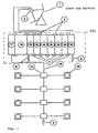
- This system consists of an antenna 1 which receives television signals of one polarity, a converter 2, in particular an LNA / LNB block, and cables 3 which connect the LNA / LNB block to a signal processing unit 400.
- This signal processing unit 400 consists of a plurality of channel-specific FM demodulators / AM modulators 19, a switching element 18, a power supply 17, connecting bridges 7, load components 8. Connected to a single distribution cable (lead) 13 with Auskoppplin 14 and user or antenna sockets 15.
- This system has the disadvantage that it requires a channel-specific FM demodulator / AM modulator 19 for each received satellite channel. If the number of satellite channels to be received is to be increased, the number of necessary FM demodulators / AM modulators must also be increased.
- Each individual FM demodulator / AM modulator, with which both the frequency demodulation and the amplitude modulator is carried out, is relatively complicated in terms of circuitry and therefore expensive.
- the cost of the system of Figure 1 increases significantly as the number of satellite channels to be distributed is increased. Even in relatively small community antenna installations with a small number of users, there are already considerable costs for a few received satellite channels.
- Such a system is known, for example, from EP-A-0 2 888 928, which discloses an apparatus having an internal unit which implements an amplifier and signal converter function.
- This internal unit has a plurality of converters, each with a tuner demodulator and an encoder modulator.
- Such a system is further known from DE-A-40 12 657, wherein in the system converters each having a tunable demodulator and an AM modulator are provided.
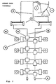
- additional distribution cable 13 can be very expensive or possibly excluded in existing systems due to spatial conditions in the buildings where the additional distribution cables would be installed.
- this prior art system requires multiple switching devices 16 to select different distribution cables and to pick up signals transmitted on the selected distribution cable.
- the use of these switching devices, which are connected to the distribution cables, is also associated with the risk that come from the switching devices formed electrical switching pulses on the distribution cables and deteriorate the transmission quality of the signals transmitted there.
- the transponder combination devices then carry those from the satellite transponder processors formed signals zwammen ("frequency mapping").
- the signals are arranged as if they had been transmitted directly from the system's antennas to this node.
- the transponder combination devices power inserter are connected downstream, which are connected on the output side with several distribution cables. The known system is thus designed circuit complex.
- the present invention seeks to provide a system for distributing signals of the type mentioned above, which allows the distribution of a larger number of channels and circuitry is designed in a simple manner, and a corresponding channel-individual converter
- the system according to the invention is characterized by a plurality of vortexes.
- the user is provided with prescribable channels via only one distribution cable, which channels are selected individually from signals originating from one antenna or from a plurality of antennas. With the individual selection of channels, the demand of system users with regard to the reception of predefinable channels can be met individually.
- the channel-specific converter provided according to the invention which convert a predeterminable channel into another channel, but also the system as a whole, are realized in a simple manner in terms of circuit technology.
- the channel-specific converters can be set to any frequency in a predefinable frequency band.
- Individual signals or channels can be superimposed by other signals or channels, with both the 1 superimposed and the superimposed signals are transmitted to the user. Usable for the user, however, are only the overlapping signals.
- the erfindungalice system that a changed demand of system users with regard to the use of predeterminable channels can be flexibly met.
- the system according to the invention can be used, inter alia, in cases in which a single distribution cable has already been laid or in cases where the laying of a further distribution cable would be complicated or precluded due to the same circumstances.
- the system according to the invention in which channels of two polarities or of two or more satellites are transmitted to user sockets via a single distribution cable, has no switching devices on the distribution cable. Thus, no electrical switching pulses are coupled to the distribution cable, so that corresponding disturbances are excluded.
- An advantageous embodiment of the invention is characterized in that the channel-specific converter of the head device are integrated in at least one converter module, wherein the converter module is connected at its input with down converters and at its output to the distribution cable.
- the converter module has at least two converters, wherein the converters in the converter module are connected to one another in chain connection (an input of a first converter module is connected to the input of a second converter module which is adjacent to the first converter module, an output of the first converter module is connected to the first converter module Output of the second converter module connected).
- This chain circuit structure is characterized by the in practice important advantage that not every channel-specific converter is to be connected via a separate cable with a down converter and that, moreover, not every channel-specific converter is to be connected via a separate cable with a mixer or adder , which is upstream of the distribution cable.
- the use of the derailleur structure saves both the separate cables and the cost of installing them.
- the channel-specific converter or its inputs and / or their outputs can be connected to one another by means of connecting bridges known per se.
- the system according to the invention enables the processing and distribution of signals of a plurality of television channels.
- several converter modules in which a variable number of channel-specific converters can be integrated. e.g. connect via a mixer ('9').
- the system according to the invention may comprise a further mixer ("5") with at least two inputs.
- one of the inputs is connected to the output of a converter module, while another input is connected directly to a down converter of an antenna
- This mixer, the output side may be connected via an amplifier with the distribution cable, makes it possible to couple more channels in the distribution cable, and although from first channels or signals that are emitted by satellites and received by satellite dishes. as well as second channels or signals emitted by terrestrial transmitters and received by conventional antennas, as well as first and second signals.
- the channel individual converters may each comprise a microprocessor which controls at least one oscillator.
- the microprocessor makes it possible to detachably connect a converter-read input device to the microprocessor and to input data into the converter or the microprocessor which designate a predefinable input channel frequency and a predefinable output channel frequency.
- the channel-independent converter can be adjusted in a particularly simple manner to a predefinable input frequency and to a predefinable output frequency, by which the frequency conversion of a channel is determined.
- the external converter input device can also be configured as a remote control transmitter.
- the channel-specific converter have an amplifier with controllable gain, wherein a mixer ("5") with at least two inputs signals of different channels of the same frequency are supplied with different signal levels. This makes it easy to superimpose different channels on the distribution cable.
- the signal level difference of at least 15 dB provided according to the invention the overlapping channels in the terminals which can be connected to the user sockets can be represented in good reception quality.
- Block A of the system according to the invention consists of antennas 1 which receive the signals from television channels transmitted via satellites. If the antennas are parabolic antennas, a down converter 2 is arranged in each case at the focal point of an antenna 1, which measures the received signals in a manner known per se from the satellite television reception frequency range of e.g. 10.7 - 12.5 GHz in the intermediate frequency range between 950 MHz and 2050 MHz (commonly referred to as "first intermediate frequency") implement.
- Such down-converters 2 with an amplifier LNA and a channel block converter LNB are known and available on the market.
- Each antenna 1 has. one or two down-converters 2 (or a down-converter with two outputs) depending on whether signals of one or two polarities (horizontal, vertical) per antenna are to be received. If the antenna 1 receives signals of one polarity, a down converter 2 is provided; receives the antenna 1 signals of two polarities, two down converter 2 are provided.
- the down converter 2 are each connected to a cable 3 on the output side.
- one or more cables 3, as shown in FIGS. 3, 4, 5, 6 and 9, lead to the signal processing unit 400 with at least one channel-specific converter 4. It can also be provided that one or more cables 3, as shown in FIGS. 3, 6 and 9, lead to a ("second") mixer 5, which is connected downstream of a channel-specific converter 4 or a converter module 40 with at least one channel-specific converter 4.
- the channel-specific converter 4 of the head device B are preferably integrated in at least one converter module 40, wherein the converter module 40 is connectable at its input via a cable 3 with a down converter (LNA / LNB) 2 and at its output to the distribution cable 13 (coaxial cable).
- the distribution cable 13 is connected to the output of an amplifier 6, which may be the ("second") mixer 5 downstream.
- Each channel-specific converter 4 the circuit design is still explained in detail with reference to Figure 7, has two inputs and two outputs.
- the channel-individual converter 4 a converter module 40 are connected together in such a way that an input (eg EC1 in Figure 7) of a first converter module with the input (eg EC2) of a second (not shown in Figure 7) converter module, which is adjacent to the first converter module is connected. Similarly, an output (e.g., SC1) of the first converter module is connected to the output (e.g., SC2) of the second converter module (ladder circuit).
- This chain circuit structure is characterized by the practically important advantage that not every channel-specific converter 4 is to be connected via a separate cable 3 with a down converter 2 and that moreover not every channel-specific converter 4 via a separate cable with a ("second") Mixer (5) to connect upstream of the distribution cable 13.
- each of the two inputs each e.g. via a respective known connection bridge 7 is connected to an input of an upstream channel-specific converter 4 and to the input of a downstream channel-specific converter 4.
- each of the two outputs is in each case connected, for example. via a respective known connection bridge 7 with an output of an upstream channel-specific converter 4 and with the output of a downstream channel-specific converter 4 is.
- an identical housing is provided for each individual channel converter 4, that is to say a housing of the same spatial dimensions, at which the input and output connections are arranged at the same locations. This allows the use of identical connection bridges 7, with each of which either an electrical connection between two inputs or between two outputs are made.
- an input of a converter 4 (first converter 4 of a converter module 40, which is drawn in each case on the right in FIGS. 4 and 5 in a converter module) with a cable 3 which generates the signals generated by the down converters 2 or in the intermediate frequency range transmits converted signals, is connected.
- An input of a converter 4 (last converter 4 of a converter module 40, which is shown on the left in FIGS. 4 and 5) is connected to a supply source 11 which supplies the converters 4 and an amplifier 12 provided for each signal processing unit 400.
- These channel-specific converter 4 take on the input from the down converters 2 and transmitted via the cable 3 signals or channels in the intermediate frequency range and put the signals or channels in the intermediate frequency range, as will be described with reference to FIGS 9 and 10.
- outputs of the channel-specific converter 4 can be terminated with an ohmic resistor 8 of 75 ohms (see Figure 3, block B, reference numeral 8 below the converters 4; right and left converter modules 40 in Figure 5.
- Figures 6 and 9, reference numeral 8 below the converter 4 These are in particular the output of a (in terms of signal flow) first converter 4 in a first converter module (right converter module in Figure 5) and the output of a (in terms of signal flow) last converter 4 in a last converter module (left converter module in Figure 5).
- a channel is selected and converted from an input frequency in the intermediate frequency range to a predefinable output frequency in the intermediate frequency range.
- a plurality of channel-specific converters 4, at least two, preferably four converters 4 can be integrated in a converter module 40. Two adjacent modules can be combined with one another via a ("first") mixer 9.
- the output of the first mixer 9 is introduced by means of a connecting cable 10 in the arrangement of supply source 11 and amplifier 12.
- the amplified signal is supplied to the second mixer 5.
- the channel-specific converter 4 is preferably configured as follows: On the input side frequency range 950 ... 1950 (or 2050) MHz input level - 50 ... -30 dBm Mirror selection (image frequency rejection) ⁇ 40 dB intermediate frequency 479.5 MHz bandwidth 27 MHz Through input loss ⁇ 1.2 dB On the output side frequency range 950 ... 1950 (or 2050) MHz Max. Output level - 25 ⁇ 5 dBm Output level control range 15 dB bandwidth 27 MHz Through output losses ⁇ 1.2 dB noise level > - 20 dBc
- the feed source 11 is preferably configured as follows: mains voltage 230V ⁇ 15% output voltage 15V / 5V Intermediate frequency loop loss ⁇ 1.2 dB
- the amplifier 12 is preferably configured as follows: bandwidth 950 ... 2050 MHz profit 23 ... 33 dB Max. Output level for two channels 115 dB ⁇ V / 6 dBm
- the first mixer 9 is preferably configured as follows: bandwidth 950 ... 2050 MHz insertion loss ⁇ 4 dB Rejection between inputs 15 dB
- first signals that form a converter module 40 (input E1) as well as second signals that are formed by the downconverters 2 (input E2) as well as third signals that are output from antennas can transmit the signals receive terrestrial transmitter, the second mixer 5 are fed.
- the distribution cable 13 is connected on the output side.
- an amplifier 6 is connected downstream, to the output side, the distribution cable 13 is connected.
- the distribution network C consists of a single distribution cable 13 on which all channels which are FM-modulated are transmitted.
- the distribution cable 13 is formed by a coaxial cable and leads to discharge devices 14 , which decouple the signal to various user sockets 15.
- FIG. 4 shows a signal processing unit 400 with a converter module 400, which consists of four channel-specific converters 4, while FIG. 5 shows a signal processing unit 400 with two converter modules 400, each consisting of four channel-specific converters 4.
- the number of channel-specific converter 4 is equal to the number of channels which are coupled into the distribution cable 13 and transmitted via the discharge devices 14 to the user sockets 15.
- the channel-specific converters can be set to predefinable input frequencies in the intermediate frequency range and to predefinable output frequencies in the intermediate frequency range.
- FIG. 7 shows an embodiment of a channel-specific converter 4.
- Two inputs EC1 and EC2 are electrically connected to each other and to a repeater 42 via a directional coupler 41.
- the inputs EC1 and EC2 are mechanically designed in such a way that known connection bridges (7 in Figure 4) can be used to connect each with an input of an adjacent channel-specific converter. In this way, several channel-specific converters can be integrated into a converter module.
- This form of connection thus consists in that each of the two inputs EC1, EC2 is connected to an input of an upstream channel-specific converter 4 or to the input of a downstream channel-specific converter 4, in each case via a known connection bridge.
- each of the two outputs SC1, SC2 of the converter 4 is in each case connected, for example via a respective known connection bridge, to an output of an upstream channel-specific converter 4 or to the output of a downstream, individual converter 4.
- This connection form has the advantage that distribution devices that would otherwise be downstream of the down converters 2 and connection cables between these distribution devices and channel-specific converters are not needed.
- the amplifier 42 amplifies the supplied signals e.g. in the frequency band from 950 to 2050 MHz.
- the signals are fed to an input-side tracking filter 43.
- This filter is a bandpass filter which is tuned to the selected input channel frequency by means of a voltage formed by a phase-locked loop (PLL) circuit 46.
- the circuit 46 is controlled by a microprocessor (MP) 49.
- MP microprocessor
- a mixer 44 connected downstream of the lag filter 43 is driven by a local oscillator (OL) 45, which in turn is driven by the PLL circuit 46.
- the mixer 44 converts the frequency of the selected channel present at the inputs EC1 and EC2 to a frequency of 479.5 MHz.
- the signal formed by the mixer 44 is fed to a low-pass filter 47 whose cut-off frequency is, for example, 600 MHz.
- a low-pass filter 47 whose cut-off frequency is, for example, 600 MHz.
- the signal is filtered by means of a SAW 50 surface acoustic wave filter, e.g. has a bandwidth of 27 MHz at a center frequency of 479.5 MHz.
- Downstream amplifiers 48 and 51 increase the signal level so that the losses caused by the SAW filter 50 are compensated.
- the mixer 52 connected downstream of the amplifier 51 mixes the signal of the 479.5 MHz frequency signal selected at the input with a signal formed by a local oscillator (OL) 53.
- the local oscillator is controlled by a PLL circuit 54.
- the PLL circuit 54 is also controlled by the microprocessor 49.
- the mixer 52 is followed by an output-side tracking filter 55 which, like the filter 43 is a band-pass filter.
- the filter 55 eliminates the unwanted signals formed in the mixture made by the mixer 52.
- At the output of the filter 55 is then the signal of the frequency converted channel, which is supplied to an amplifier 56.
- the gain of the amplifier 56 is controllable, so that the levels of the frequency converted channel signal can be set to predetermined values (see, for example, in Fig. 8, the channels 1 and 5).
- a downstream directional coupler 57 couples the amplified signal to the outputs SC1, SC2.
- the outputs SC1 and SC2 are designed mechanically in such a way that known connection bridges (7 in FIG. 4) can be used for connection to one output of an adjacent channel-specific converter.
- the converters 4 may include a microprocessor 49 which controls the PLL circuits 46 and 54 and determines the input and output frequency of the channel signal of the converters 4. Furthermore, the microprocessor 49 may control the amplifier 56. To the microprocessor 49 may e.g. an input unit 16 can be connected via a 4-cable bus, via which data of a predefinable input and output frequency and / or control data for the amplifier 56 (signal amplification parameter) can be input to the microprocessor 49.
- the input unit 16 may comprise a controller 162 (in particular a microprocessor MP), a program associated with the controller 162 being e.g. depending on the cut-off frequencies of the respective intermediate frequency range (950 MHz, 2050 MHz), channel bandwidths and channel spacings and signal levels of the channel signals, data corresponding to given technical specifications and input to the microprocessor 49 of the channel-specific converter 4.
- the input unit 16 includes a keyboard 161, the controller 162, and a display 163. On the display, data inputted to the keyboard 161, prompt information, and information indicating the state of the converter after its setting by the input data are displayed.
- the input unit 16 can be designed as a remote control transmitter with a transmitting device which transmits the data to be input to a receiving device which is connected to the microprocessor 49 of the channel-specific converter.
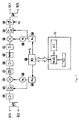
- FIG. 8 shows a second mixer 5, which is also shown in FIG. 3, block B.
- the second mixer 5 has e.g. three inputs E1, E2, E3 and an output S to which the distribution cable 13 is connected.
- the distribution cable 13 is preferably a coaxial cable, but it can also be provided a glass fiber.
- the input E1 is connected directly via a cable to one or more converter modules 40; to the input E2, a cable 3 with a down converter (2 in Figure 3) is connected directly, while the input E3 is connected to a system for receiving terrestrial channels.
- the signals E1, 2, 3, 4, 5 and 6 are input to the input E1 which originate from a satellite, have a bandwidth of 27 MHz, and, as described, have been converted by channel-specific converters in the frequency band between 950 and 2050 MHz.
- the input E2 is supplied with signals of channels 7, 8, 9, 10, 11, 12, 13 and 14 originating from a satellite, having a bandwidth of 27 MHz and, as described, channel-specific converters in the frequency band between 950 and 2050 MHz have been implemented.
- At the entrance E3 are 6 terrestrial TV channels with 8 MHz bandwidth in the frequency band between 47 and 860 MHz.
- the signals of the channels which are present at the input E1 are supplied by the channel-specific converters 4, in which the frequency conversion and the formation of the respective levels with respect to the coupling of the signals via the mixer output S in the distribution cable 13.
- the channels 2, 4 and 6, which are present at the input E1 were so frequency converted in the channel-specific converters 4 that no channels of the same frequencies are present at the input E2.
- the channels 1 and 3 at the input E1 are arranged in frequencies between the non-desired channels 7 and 8 or 9 and 10, which are present at the input E2.
- the signal or Power level of channel 1 is set to a value of at least 15 dB above the corresponding level of channels 7 and 8; and the signal or power level of the channel 3 is set to a value of at least 15 dB above the corresponding level of the channels 9 and 10.
- the channel 5 of the input E1 is arranged in the same frequency as the unwanted channel 12 which is present at the input E2, wherein the signal or power level of the channel 5 is at least 20 dB above the corresponding level of the channel 12.
- the channels in the frequency band from 47 to 860 MHz and the channels 1, 2, 3, 4, 11, 5, 13, 6 and 14 in the frequency band from 950 to 2050 MHz made available to the system user.
- the channels 7, 8, 9, 10 and 12 are transmitted on the distribution cable 13; However, these are superimposed so that they are not made available to the system user.
- the signal level difference of at least 15 dB provided according to the invention the overlapping channels in the terminals which can be connected to the user sockets can be represented in good reception quality.
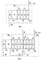
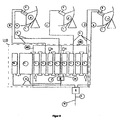
- FIG. 9 shows an exemplary embodiment of the system according to the invention, which is also shown in FIG. It is assumed that signals of different television channels are received and processed, which come from three satellites of different orbital position with horizontal and vertical position.
- circuit points d, e, f, g, h, i, j, k, I, m, n, and o are indicated.
- FIG. 10 shows the channels at the circuit points d - o shown in FIG. 9.
- the channels 70, 72, 92 are in vertical polarity and the channels 71, 93, 93 are in horizontal polarity.
- the channels 65,..., 69 are in only one polarity.
- Each down converter 2 ( Figure 9) selects one polarity and converts the 10.9-12.5 GHz frequency band to the 950-2050 MHz frequency band such that in each cable 3 at the nodes g, h, i, j, k are the channels that belong to the same satellites and to the same polarity.
- the channels 70, 72,... 92 are present at the node g, at the node h the channels 71, 73,... 93, at the node i the channels 65 - 69, at the node j the channels 49, 51 ... 63, 33 .... 47, 1, 3, ... 31 and at the node k the channels 50, 52 ... 64; 34, 36, ... 48; 2, 4 ... 32.
- converter modules 40 are provided at the circuit points g, h, i, j, wherein the channel-specific converters 4 of the modules 40 are set to the input frequencies of each of the selected channels and to the output frequencies to which the channels are to be arranged. These output frequencies are occupied frequencies of unwanted channels to be overlaid or free frequencies.
- each converter module 40 channels are provided according to the invention, which have a different frequency position relative to the frequency position at the input of the modules.
- the channels 72, 82, 77 and 89 occur at a frequency position different from the frequency position of the channels at the nodes g and h.
- the channels 65, 68, 17 and 41 which come from the circuit points i and j, also in different frequency position.
- all selected channels originating from the nodes g, h, i and j are present in frequency positions differ from the original frequency positions. These channels are introduced via the supply source 11 into the amplifier 12, which amplifies the signal levels of the channels.
- the channels which are present at the node n are mixed with the channels which are present at the node k.
- the channels which are present at node n are superimposed on the channels of the same frequency which are present at node k.
- the channels at node n must have a higher signal level of at least 15, but preferably 18 to 20 dB, above the signal levels of the channels at node k to be superimposed. This difference in level ensures that the channel that overlays another channel is received without interference from the channel that has been overlaid.
- channel 65 is superimposed on channel 60 (compare greater amplitude of 65 versus 60), channel 72 on channel 36, channel 68 on channel 44, channel 82 the channel 2, the channel 77 the channel 6, the channel 17 the channel 12, channel 89 the channel 18 and channel 41 the channel 24th
- signals in particular television signals transmitted by satellites of different channels
- the signals are received in a signaling device A and the received signals of a certain polarity (H, V) converted from a receiving frequency band into signals in an intermediate frequency band.
- the converted into the intermediate frequency band signals are processed and the processed signals are transmitted via a single distribution cable 13 in the intermediate frequency band to user sockets 15.
- individual predeterminable channels in the intermediate frequency band are converted into other channels in the intermediate frequency band.
- first channels are mixed with second channels in the intermediate frequency band and the first and second channels are transmitted via the distribution cable 13.
- different signal levels are formed for two channels of the same frequency converted into the intermediate frequency band, the signal levels of the signals of different channels differing by at least 15 dB.
Landscapes
- Physics & Mathematics (AREA)
- Astronomy & Astrophysics (AREA)
- General Physics & Mathematics (AREA)
- Engineering & Computer Science (AREA)
- Signal Processing (AREA)
- Input Circuits Of Receivers And Coupling Of Receivers And Audio Equipment (AREA)
- Radio Relay Systems (AREA)
- Two-Way Televisions, Distribution Of Moving Picture Or The Like (AREA)
- Details Of Television Systems (AREA)
Description
Die vorliegende Erfindung betrifft ein System zur Verteilung von Signalen, insbesondere ein Gemeinschaftsantennensystem zur Verteilung von Fernsehsignalen unterschiedlicher Kanäle nach dem Oberbegriff des Anspruchs 1.The present invention relates to a system for distributing signals, in particular a community antenna system for distribution of television signals of different channels according to the preamble of
Zur Zeit werden zu diesem Zweck im wesentlichen zwei Systeme benutzt, die in den Figuren 1 und 2 schematisch dargestellt sind:At present, essentially two systems are used for this purpose, which are shown schematically in FIGS. 1 and 2:
In dem ersten System nach dem Stand der Technik, welches in Figur 1 dargestellt ist, werden von der Antenne empfangene Signale nach einer Verstärkung und Umsetzung durch an sich bekannte Einheiten (low-noise amplifier LNA, low-noise block converter LNB) jeweils kanalindividuell frequenzdemoduliert. Anschließend werden die kanalindividuellen frequenzdemodulierten Signale in einem herkömmlichen UHF-Fernsehkanal amplitudenmoduliert.In the first system according to the prior art, which is shown in FIG. 1, signals received by the antenna are frequency-demodulated channel-individually after amplification and conversion by units known per se (low-noise amplifier LNA) , Subsequently, the channel-specific frequency demodulated signals are amplitude modulated in a conventional UHF television channel.
Dieses System besteht aus einer Antenne 1, die Fernsehsignale einer Polarität empfängt, einem Konverter 2, insbesondere einem LNA/LNB-Block, und Kabeln 3, die den LNA/LNB-Block mit einer Signalverarbeitungseinheit 400 verbinden. Diese Signalverarbeitungseinheit 400 besteht aus einer Mehrzahl kanalindividueller FM-Demodulatoren/ AM-Modulatoren 19, einem Schaltelement 18, einer Stromversorgung 17, Verbindungsbrücken 7, Lastkomponenten 8. Daran angeschlossen ist ein einziges Verteilkabel (Ableitung) 13 mit Auskopplern 14 und Benutzer- bzw. Antennensteckdosen 15. Dieses System hat den Nachteil, daß es für jeden empfangenen Satellitenkanal einen kanalindividuellen FM-Demodulator/AM-Modulator 19 benötigt. Soll die Anzahl der zu empfangenden Satellitenkanäle erhöht werden, ist auch die Anzahl der notwendigen FM-Demodulatoren/AM-Modulatoren zu erhöhen. Jeder einzelne FM-Demodulator/AM-Modulator, mit dem sowohl die Frequenzdemodulation als auch die Amplitudenmodulätion durchgeführt wird, ist schaltungstechnisch relativ komplex ausgestaltet und damit kostenaufwendig. Die Kosten des Systems nach Figur 1 erhöhen sich erheblich, wenn die Anzahl der zu verteilenden Satellitenkanäle erhöht wird. Schon in relativ kleinen Gemeinschaftsantenneninstallationen mit einer kleinen Anzahl von Benutzern ergeben sich bereits bei wenigen empfangenen Satellitenkanälen erhebliche Kosten.This system consists of an
Ein solches System ist beispielsweise aus der EP-A-0 2 888 928 bekannt, die eine Vorrichtung mit einer internen Einheit offenbart, die eine Verstärker- und Signalumsetzerfunktion realisiert. Diese interne Einheit weist mehrere Konverter mit je einem Tuner-Demodulator und einem Kodierer-Modulator auf.Such a system is known, for example, from EP-A-0 2 888 928, which discloses an apparatus having an internal unit which implements an amplifier and signal converter function. This internal unit has a plurality of converters, each with a tuner demodulator and an encoder modulator.
Ein solches System ist weiterhin aus der DE-A-40 12 657 bekannt, wobei in dem System Umsetzer mit jeweils einem abstimmbaren Demodulator und einem AM-Modulator vorgesehen sind.Such a system is further known from DE-A-40 12 657, wherein in the system converters each having a tunable demodulator and an AM modulator are provided.
Bei dem zweiten System nach dem Stand der Technik, welches in Figur 2 dargestellt ist, erfolgt die Verteilung von Fernsehsatellitenkanälen bis zum Systembenutzer, ohne daß die Signale zuvor frequenzdemoduliert und amplitudenmoduliert werden. Ein solches System ist aus dem US-Patent 4,608,710 bekannt. Die Signale der Fernsehsatellitenkanäle werden also frequenzmoduliert (z.B. im Frequenzbereich zwischen 950 MHz und 2050 MHz) verteilt. Dieses System nach Figur 2 erfordert zwar im Unterschied zu dem System nach Figur 1 keine den LNA/LNB-Blöcken nachgeschalteten kanal individuellen FM-Demodulatoren/AM-Modulatoren; dieses System hat aber den Nachteil, daß für die Verteilung der Satellitenkanäle, die von zwei unterschiedlichen Polaritäten oder von mehr als einem Satelliten stammen, mehr als ein Verteilkabel 13 zu installieren ist. Die Installation zusätzlicher Verteilkabel 13 kann in bereits bestehenden Anlagen aufgrund räumlicher Gegebenheiten in den Gebäuden, in denen die zusätzlichen Verteilkabel zu installieren wären, sehr aufwendig oder eventuell ausgeschlossen sein. Weiterhin erfordert dieses System nach dem Stand der Technik mehrere Schalteinrichtungen 16, um unterschiedliche Verteilkabel auszuwählen und auf dem ausgewählten Verteilkabel übertragene Signale abzugreifen. Die Verwendung dieser Schalteinrichtungen, die an den Verteilkabeln angeschlossen sind, ist zudem mit der Gefahr verbunden, daß von den Schalteinrichtungen gebildete elektrische Schaltimpulse auf die Verteilkabel gelangen und die die Übertragungsqualität der dort übertragenen Signale verschlechtern.In the second prior art system shown in Figure 2, the distribution of television satellite channels to the system user is accomplished without the signals being previously frequency demodulated and amplitude modulated. Such a system is known from U.S. Patent 4,608,710. The signals of the television satellite channels are thus distributed in a frequency modulated manner (for example in the frequency range between 950 MHz and 2050 MHz). In contrast to the system according to FIG. 1, this system according to FIG. 2 does not require any channels of individual FM demodulators / AM modulators connected downstream of the LNA / LNB blocks; However, this system has the disadvantage that more than one
Aus der DE-OS 41 17 208 A1 ist ein Gerät für Satellitenfernseh-Empfangseinrichtungen bekannt, wobei Fernsehsignale verarbeitet werden, die von einer Parabol-Antenne empfangen werden und horizontal polarisierte Kanäle undFrom DE-OS 41 17 208 A1 a device for satellite television receiving devices is known, wherein television signals are processed, which are received by a satellite dish and horizontally polarized channels and
vertikal polarisierte Kanäle aufweisen. Zur Vermeidung einer aufwendigen Verkabelung werden die horizontal polarisierten Kanäle und die vertikal polarisierten Kanäle voneinander getrennt und blockweise in getrennte Frequenzbänder umgesetzt. Die so getrennten Blöcke von Kanälen werden auf eine gemeinsame Leitung geschaltet. Das bekannte Gerät ermöglicht lediglich die blockweise Umsetzung von Kanälen. Ähnlich strukturierte Systeme sind auch aus der Europäischen Patentanmeldung 0 597 783 und aus der DE-U-93 06 499 bekannt.having vertically polarized channels. To avoid cumbersome wiring, the horizontally polarized channels and the vertically polarized channels are separated from each other and converted block by block into separate frequency bands. The thus separated blocks of channels are switched to a common line. The known device only allows the blockwise implementation of channels. Similarly structured systems are also known from European Patent Application 0 597 783 and from DE-U-93 06 499.
Aus dem US-Patent 5,073,930 ist ein Verfahren und ein System zum Empfangen und Verteilen von Fernsehsignalen bekannt, die von Satelliten übertragen worden sind. Dieses vorbekannte System ist in der Weise strukturiert, daß Low-Noise Verstärkern (LNA) und Low-Noise Block-Konvertern (LNB) sogenannte powers splitter nachgeschaltet sind, wobei jede Übertragungsleitung am Ausgang eines Low-Noise-Block-Konverters (LNB) in 8 Übertragungsleitungen aufgesplittet wird. Diese Übertragungsleitungen werden über ein Verbindungsbusnetzwerk auf acht Satellitentransponder-Prozessoren geführt. Die Satellitentransponder-Prozessoren setzen jeweils Signale eines Kanals in eine neue Frequenzlage um. Ausgangsseitig sind die Satellitentransponder-Prozessoren mit Transponder-Kombinationseinrichtungen verbunden. Die Transponder-Kombinationseinrichtungen führen dann die von den Satellitentransponder-Prozessoren gebildeten Signale zwammen ("frequency mapping"). Dabei werden die Signale so angeordnet, als ob sie direkt von den Antennen des Systems zu diesem Schaltungspunkt übertragen worden wären. Weiterhin sind den Transponder-Kombinationseinrichtungen power inserter nachgeschaltet, die ausgangsseitig mit mehreren Verteilkabeln verbunden sind. Das bekannte System ist damit schaltungstechnisch komplex ausgestaltet.From U.S. Patent 5,073,930 a method and system for receiving and distributing television signals transmitted by satellites is known. This prior art system is structured in such a way that low-noise amplifiers (LNA) and low-noise block converters (LNB) are connected downstream so-called power splitter, each transmission line at the output of a low-noise block converter (LNB) in 8 transmission lines is split. These transmission lines are routed via a link bus network to eight satellite transponder processors. The satellite transponder processors each convert signals of a channel into a new frequency position. On the output side, the satellite transponder processors are connected to transponder combination devices. The transponder combination devices then carry those from the satellite transponder processors formed signals zwammen ("frequency mapping"). The signals are arranged as if they had been transmitted directly from the system's antennas to this node. Furthermore, the transponder combination devices power inserter are connected downstream, which are connected on the output side with several distribution cables. The known system is thus designed circuit complex.
Ausgehend von diesem Stand der Technik liegt der Erfindung die Aufgabe zugrunde, ein System zur Verteilung von Signalen der eingangs genannten Art anzugeben, welche die Verteilung einer größeren Kanalanzahl ermöglicht und schaltungstechnisch in einfacher Weise ausgestaltet ist, sowie einen entsprechenden kanalindividuellen KonverterBased on this prior art, the present invention seeks to provide a system for distributing signals of the type mentioned above, which allows the distribution of a larger number of channels and circuitry is designed in a simple manner, and a corresponding channel-individual converter
Diese Aufgabe wird erfindungsgemäß durch ein System nach Anspruch 1 und einen kanalindividuellen Konverter nach Anspruch 14 gelöst.This object is achieved by a system according to
Das erfindungsgemäße System zeichnet sich durch eine Mehrzahl von Vortellen auf. Erfindungsgemäß werden dem Benutzer über nur ein Verteilkabel vorgebbare Kanäle zur Verfügung gestellt, die individuell aus Signalen ausgewählt werden, die von einer Antenne oder von mehreren Antennen stammen. Mit der individuellen Auswahl von Kanälen kann der Nachfrage von Systembenutzem hinsichtlich des Empfangs vorgebbarer Kanäle individuell entsprochen werden. Die erfindungsgemäß vorgesehenen kanalindividuellen Konverter, die einen vorgebbaren Kanal in einen anderen Kanal umsetzen, aber auch das System insgesamt sind schaltungstechisch in einfacher Weise realisiert. Die kanalindividuellen Konverter sind auf beliebige Frequenzen in einem vorgebbaren Frequenzband einstellbar. Einzelne Signale bzw. Kanäle lassen sich durch andere Signale bzw. Kanäle überlagern, wobei sowohl die 1 überlagerten als auch die überlagernden Signale zum Benutzer übertragen werden. Nutzbar für den Benutzer sind jedoch nur die überlagernden Signale. Damit ermöglicht das erfindungagemäße System, daß einer geänderten Nachfrage der Systembenutzer hinsichtlich der Nutzung vorgebbarer Kanäle flexibel entsprochen werden kann.The system according to the invention is characterized by a plurality of vortexes. According to the invention, the user is provided with prescribable channels via only one distribution cable, which channels are selected individually from signals originating from one antenna or from a plurality of antennas. With the individual selection of channels, the demand of system users with regard to the reception of predefinable channels can be met individually. The channel-specific converter provided according to the invention, which convert a predeterminable channel into another channel, but also the system as a whole, are realized in a simple manner in terms of circuit technology. The channel-specific converters can be set to any frequency in a predefinable frequency band. Individual signals or channels can be superimposed by other signals or channels, with both the 1 superimposed and the superimposed signals are transmitted to the user. Usable for the user, however, are only the overlapping signals. Thus, the erfindungagemäße system that a changed demand of system users with regard to the use of predeterminable channels can be flexibly met.
Das erfindungsgemäße System ist unter anderem in den Fällen einsetzbar, in denen bereits ein einziges Verteilkabel verlegt ist bzw. in den Fällen, in denen die Verlegung eines weiteren Verteilkabels aufgrund nämlicher Gegebenheiten aufwendig oder ausgeschlossen wäre.The system according to the invention can be used, inter alia, in cases in which a single distribution cable has already been laid or in cases where the laying of a further distribution cable would be complicated or precluded due to the same circumstances.
Auch weist das erfindungsgemäße System, in dem Kanäle zweier Polaritäten oder von zwei oder mehr Satelliten über ein einziges Verteilkabel zu Benutzersteckdosen übertragen werden, an dem Verteilkabel keine Schaltvorrichtungen auf. Damit werden keine elektrischen Schaltimpulse aul das Verteilkabel eingekoppelt, so daß entsprechende Störungen ausgeschlossen werden.Also, the system according to the invention, in which channels of two polarities or of two or more satellites are transmitted to user sockets via a single distribution cable, has no switching devices on the distribution cable. Thus, no electrical switching pulses are coupled to the distribution cable, so that corresponding disturbances are excluded.
Eine vorteilhafte der Ausführungsform der Erfindung ist dadurch gekennzeichnet, daß die kanalindividuellen Konverter der Kopfeinrichtung in wenigstens einem Konvertermodul integriert sind, wobei das Konvertermodul an seinem Eingang mit Abwärtsumsetzern und an seinem Ausgang mit dem Verteilkabel verbunden ist. Vorzugsweise weist das Konvertermodul wenigstens zwei Konverter auf, wobei die Konverter in dem Konvertermodul untereinander in Kettenschaltung verbunden sind (ein Eingang eines ersten Konvertermoduls ist mit dem Eingang eines zweiten Konvertermoduls verbunden, das dem ersten Konvertermodul benachbart ist; ein Ausgang des ersten Konvertermoduls ist mit dem Ausgang des zweiten Konvertermoduls verbunden).An advantageous embodiment of the invention is characterized in that the channel-specific converter of the head device are integrated in at least one converter module, wherein the converter module is connected at its input with down converters and at its output to the distribution cable. Preferably, the converter module has at least two converters, wherein the converters in the converter module are connected to one another in chain connection (an input of a first converter module is connected to the input of a second converter module which is adjacent to the first converter module, an output of the first converter module is connected to the first converter module Output of the second converter module connected).
Diese Kettenschaltungs-Struktur zeichnet sich durch den in der Praxis wichtigen Vorteil aus, daß nicht jeder kanalindividuelle Konverter über ein separates Kabel mit einem Abwärtsumsetzer zu verbinden ist und daß darüberhinaus nicht jeder kanalindividuelle Konverter über ein separates Kabel mit einem Mischer bzw. Addierer zu verbinden ist, der dem Verteilkabel vorgeschaltet ist. Durch die Verwendung der Kettenschaltungs-Struktur werden zum einem die separaten Kabel und zum anderen die Kosten für deren Installation eingespart. insbesondere lassen sich die kanalindividuellen Konverter bzw. deren Eingänge und/oder deren Ausgänge durch an sich bekannte Verbindungsbrücken miteinander verbinden.This chain circuit structure is characterized by the in practice important advantage that not every channel-specific converter is to be connected via a separate cable with a down converter and that, moreover, not every channel-specific converter is to be connected via a separate cable with a mixer or adder , which is upstream of the distribution cable. The use of the derailleur structure saves both the separate cables and the cost of installing them. In particular, the channel-specific converter or its inputs and / or their outputs can be connected to one another by means of connecting bridges known per se.
Das erfindungsgemäße System ermöglicht die Verarbeitung und Verteilung von Signalen einer Vielzahl von Femsehkanälen. So lassen sich mehrere Konvertermodule, in die eine veränderbare Anzahl von kanalindividuellen Konvertern integriert werden können. z.B. über einen Mischer ('9') miteinander verbinden.The system according to the invention enables the processing and distribution of signals of a plurality of television channels. Thus, several converter modules, in which a variable number of channel-specific converters can be integrated. e.g. connect via a mixer ('9').
Das erfindungsgemäße System kann einen weiteren Mischer ("5") mit wenigstens zwei Eingängen aufweisen. Dabei ist einer der Eingänge mit dem Ausgang eines Konvertermoduls verbunden, während ein weiterer Eingang direkt mit einem Abwärtskonverter einer Antenne verbunden ist Dieser Mischer, der ausgangsseitig eventuell Ober einen Verstärker mit dem Verteilkabel verbunden ist, ermöglicht es, weitere Kanäle in das Verteilkabel einzukoppeln, und zwar von ersten Kanälen bzw. Signalen, die von Satelliten abgestrahlt und von Parabolantennen empfangen werden. als auch von zweiten Kanälen bzw. Signalen, die von terrestrischen Sendern ausgestrahlt und von herkömmlichen Antennen empfangen werden, als auch von ersten und zweiten Signalen.The system according to the invention may comprise a further mixer ("5") with at least two inputs. In this case, one of the inputs is connected to the output of a converter module, while another input is connected directly to a down converter of an antenna This mixer, the output side may be connected via an amplifier with the distribution cable, makes it possible to couple more channels in the distribution cable, and although from first channels or signals that are emitted by satellites and received by satellite dishes. as well as second channels or signals emitted by terrestrial transmitters and received by conventional antennas, as well as first and second signals.
Die kanal individuellen Konverter können jeweils einen Mikroprozessor aufweisen, der mindestens einen Oszillator steuert. Der Mikroprozessor ermöglicht es, eine konverterexteme Eingabeeinrichtung an den Mikroprozessor lösbar anzuschließen und Daten in den Konverter bzw den Mikroprozessor einzugeben, die eine vorgebbare Eingangskanalfrequenz und eine vorgebbare Ausgangekanalfrequenz bezeichnen. Auf diese Weise lassen sich die kanalindivlduellen Konverter in besonders einfacher Weise auf eine vorgebbare Eingangsfrequenz und auf eine vorgebbare Ausgangsfrequenz einstellen, durch die die Frequenzumsetzung eines Kanals bestimmt wird. Die konverterexterne Eingabeeinrichtung kann auch als Fernbedienungsgeber ausgestaltet sein.The channel individual converters may each comprise a microprocessor which controls at least one oscillator. The microprocessor makes it possible to detachably connect a converter-read input device to the microprocessor and to input data into the converter or the microprocessor which designate a predefinable input channel frequency and a predefinable output channel frequency. In this way, the channel-independent converter can be adjusted in a particularly simple manner to a predefinable input frequency and to a predefinable output frequency, by which the frequency conversion of a channel is determined. The external converter input device can also be configured as a remote control transmitter.
Die kanalindividuellen Konverter weisen einen Verstärker mit steuerbarem Gewinn auf, wobei einem Mischer ("5") mit wenigstens zwei Eingängen Signale unterschiedlicher Kanäle derselben Frequenz mit unterschiedlichen Signalpegeln zugeführt werden. Damit lassen sich auf einfache Weise unterschiedliche Kanäle auf dem Verteilkabel überlagern. Bei dem erfindungsgemäß vorgesehen Signalpegelunterschied von mindestens 15 dB lassen sich die überlagernden Kanäle in den an den Benutzersteckdosen anschließbaren Endgeräten in guter Empfangsqualität darstellen.The channel-specific converter have an amplifier with controllable gain, wherein a mixer ("5") with at least two inputs signals of different channels of the same frequency are supplied with different signal levels. This makes it easy to superimpose different channels on the distribution cable. In the case of the signal level difference of at least 15 dB provided according to the invention, the overlapping channels in the terminals which can be connected to the user sockets can be represented in good reception quality.
Die dargestellten Eigenschaften der Erfindung sowie weitere Eigenschaften und Vorteile werden nun anhand der Zeichnungen beschrieben, in denen Ausführungsbeispiele der Erfindung dargestellt sind.The illustrated features of the invention as well as other features and advantages will now be described with reference to the drawings, in which embodiments of the invention are shown.
Es zeigt:
- Fig. 1 und 2
- Signalverteilsysteme nach dem Stand der Technik;
- Fig. 3
- ein erstes Ausführungsbeispiel des Signalverteilsystems gemäß der Erfindung;
- Fig. 4 - 6
- Ausführungsbeispiele von Signalverarbeitungseinheiten eines erfindungsgemäßen Signalverteilsystems nach Figur 3;
- Fig. 7
- ein Ausführungsbeispiel eines kanalindividuellen Konverters in einer Signalverarbeitungseinheit nach den Figuren 3 - 6;
- Fig. 8
- ein Ausführungsbeispiel eines Mischers, der in einer Signalverarbeitungseinheit nach den Figuren 3 - 6 mindestens einem kanalindividuellen Konverter nachgeschaltet ist;
- Fig. 9
- ein Ausführungsbeispiel eines erfindungsgemäßen Signalverteilsystems mit ausgewählten Schaltungspunkten, und
Figur 10- Diagramme von Kanalsignalfrequenzen an den Schaltungspunkten des erfindungsgemäßen Signalverteilsystems nach Figur 9.
- Fig. 1 and 2
- Signal distribution systems according to the prior art;
- Fig. 3
- a first embodiment of the signal distribution system according to the invention;
- Fig. 4-6
- Embodiments of signal processing units of a signal distribution system according to the invention according to Figure 3;
- Fig. 7
- an embodiment of a channel-specific converter in a signal processing unit according to Figures 3-6;
- Fig. 8
- an embodiment of a mixer, which is connected downstream of at least one channel-individual converter in a signal processing unit according to Figures 3-6;
- Fig. 9
- an embodiment of a signal distribution system according to the invention with selected circuit points, and
- FIG. 10
- Diagrams of channel signal frequencies at the circuit points of the signal distribution system according to the invention according to FIG. 9.
Das in den Zeichnungen dargestellte Signalverteilsystem, so wie es auch in Fig. 3 dargestellt ist, besteht aus drei Blöcken A, B und C. Block A ist eine Signalgebereinrichtung, Block B ist eine Kopfeinrichtung mit einer Signalverarbeitungseinheit und Block C stellt das Verteilnetz dar. Die Blöcke A, B und C sind wie folgt ausgestaltet:
- 1. Block A ist eine Signalgebereinrichtung, die aus mindestens einer
Antenne 1 sowie aus bekannten Abwärtsumsetzern 2 (low-noise amplifier LNA, low-noise block converter LNB) besteht. Die empfangenen Signale können von verschiedenen Rundfunk- und/oder Fernmeldesatelliten stammen und/oder verschiedene Polaritäten (horizontal, vertikal) aufweisen.Die Abwärtsumsetzer 2 setzen die empfangenen Signale in an sich bekannter Weise aus dem Empfangsfrequenzbereich von z.B. 11,7 - 12,5 GHz; 10,7 - 11,7 GHz; 12,5 - 12,75GHz oder vorzugsweise 10,7 - 12,5 GHz in einen Zwischenfrequenzbereich von z.B. 950 - 1760 MHz oder vorzugsweise 950 MHz und 2050 MHz um; - 2. Block B ist eine Kopfeinrichtung mit einer
Signalverarbeitungseinrichtung 400, in der kanalindividuelle Konverter 4 angeordnet sind.Die kanalindividuellen Konverter 4 werden noch detailliert insbesondere anhandvon Figur 7 beschrieben. VerschiedeneAusgestaltungen der Signalverarbeitungseinrichtung 400 sind inden Figuren - 3. Das Verteilungsnetz C weist
ein einziges Verteilkabel 13 auf, über das die Signale über Abgreif- bzw.Ableiteinrichtungen 14bis zu Benutzersteckdosen 15 übertragen werden.
- 1. Block A is a signaling device which consists of at least one
antenna 1 as well as known down-converters 2 (low-noise amplifier LNA). The received signals may come from different broadcast and / or telecommunications satellites and / or have different polarities (horizontal, vertical). The downconverter 2 set the received signals in a conventional manner from the receiving frequency range of, for example 11.7 - 12.5 GHz; 10.7 - 11.7 GHz; 12.5 - 12.75 GHz or preferably 10.7 - 12.5 GHz in an intermediate frequency range of eg 950 - 1760 MHz or preferably 950 MHz and 2050 MHz in order; - 2. Block B is a head device with a
signal processing device 400, are arranged in the channel-specific converter 4. The channel-specific converter 4 will be described in more detail in particular with reference to FIG. Various embodiments of thesignal processing device 400 are shown in Figures 3, 4, 5 and 6; - 3. The distribution network C has a
single distribution cable 13, via which the signals are transmitted via tapping ordischarge devices 14 touser sockets 15.
Block A des erfindungsgemäßen Systems, d.h., die Signalgebereinrichtung, wie sie beispielsweise in Fig. 3 dargestellt ist, besteht aus Antennen 1, die die Signale von Fernsehkanälen, die über Satelliten übertragen werden, empfangen. Sofern die Antennen Parabolantennen sind, ist jeweils im Brennpunkt einer Antenne 1 ein Abwärtsumsetzer (down converter) 2 angeordnet, die die empfangenen Signale in an sich bekannter Weise aus dem Satellitenfernsehempfangsfrequenzbereich von z.B. 10,7 - 12,5 GHz in den Zwischenfrequenzbereich zwischen 950 MHz und 2050 MHz (üblicherweise als "erste Zwischenfrequenz" bezeichnet) umsetzen. Derartige Abwärtsumsetzer 2 mit einem Verstärker LNA und einem Kanalblockumsetzer LNB sind bekannt und auf dem Markt erhältlich.Block A of the system according to the invention, that is, the signaling device as shown, for example, in Fig. 3, consists of
Jede Antenne 1 weist. einen oder zwei Abwärtsumsetzer 2 (bzw einen Abwärtsumsetzer mit zwei Ausgängen) in Abhängigkeit davon auf, ob Signale einer oder zweier Polaritäten (horizontal, vertikal) pro Antenne empfangen werden sollen. Empfängt die Antenne 1 Signale einer Polarität, ist ein Abwärtsumsetzer 2 vorgesehen; empfängt die Antenne 1 Signale zweier Polaritäten, sind zwei Abwärtsumsetzer 2 vorgesehen.Each
Die Abwärtsumsetzer 2 sind ausgangsseitig jeweils mit einem Kabel 3 verbunden. In unterschiedlichen Ausführungsformen der Erfindung führen ein oder mehrere Kabel 3, wie in den Figuren 3, 4, 5, 6 und 9 dargestellt, zu der Signalverarbeitungseinheit 400 mit mindestens einem kanalindividuellen Konvertern 4. Es kann auch vorgesehen sein, daß ein oder mehrere Kabel 3, wie in den Figuren 3, 6 und 9 dargestellt, zu einem ("zweiten") Mischer 5 führen, der einem kanalindividuellen Konverter 4 oder einem Konvertermodul 40 mit mindestens einem kanalindividuellen Konverter 4 nachgeschaltet ist.The down
Die kanalindividuellen Konverter 4 der Kopfeinrichtung B sind vorzugsweise in wenigstens einem Konvertermodul 40 integriert, wobei das Konvertermodul 40 an seinem Eingang über ein Kabel 3 mit einem Abwärtsumsetzer (LNA/LNB) 2 und an seinem Ausgang mit dem Verteilkabel 13 (Koaxialkabel) verbindbar ist. Vorzugsweise ist das Verteilkabel 13 an den Ausgang eines Verstärkers 6 angeschlossen, der dem ("zweiten") Mischer 5 nachgeschaltet sein kann.The channel-
Jeder kanalindividueller Konverter 4, deren schaltungstechnischer Aufbau noch anhand von Figur 7 detailliert erläutert wird, weist zwei Eingänge und zwei Ausgänge auf.Each channel-
Wie in den Figuren 3, 4, 5, 6 und 9 dargestellt, sind die kanalindividuellen Konverter 4 eines Konvertermoduls 40 in der Weise miteinander verbunden, daß ein Eingang (z.B. EC1 in Figur 7) eines ersten Konvertermoduls mit dem Eingang (z.B. EC2) eines zweiten (in Figur 7 nicht dargestellten) Konvertermoduls, das dem ersten Konvertermodul benachbart ist, verbunden ist. Ebenso ist ein Ausgang (z.B. SC1) des ersten Konvertermoduls mit dem Ausgang (z. V. SC2) des zweiten Konvertermoduls verbunden (Kettenschaltung).As shown in Figures 3, 4, 5, 6 and 9, the channel-individual converter 4 a
Diese Kettenschaltungs-Struktur zeichnet sich durch den praktisch wichtigen Vorteil aus, daß nicht jeder kanalindividuelle Konverter 4 über ein separates Kabel 3 mit einem Abwärtsumsetzer 2 zu verbinden ist und daß darüberhinaus nicht jeder kanalindividueller Konverter 4 über ein separates Kabel mit einem ("zweiten") Mischer (5) zu verbinden, der dem Verteilkabel 13 vorgeschaltet ist.This chain circuit structure is characterized by the practically important advantage that not every channel-
Dabei kann vorgesehen sein, daß jederder beiden Eingänge jeweils z.B. über je eine bekannte Verbindungsbrücke 7 mit einem Eingang eines vorgeschalteten kanalindividuellen Konverters 4 bzw. mit dem Eingang eines nachgeschalteten kanalindividuellen Konverters 4 verbunden ist. Ebenso kann hinsichtlich der Ausgänge vorgesehen sein, daß jeder der beiden Ausgänge jeweils z.B. über je eine bekannte Verbindungsbrücke 7 mit einem Ausgang eines vorgeschalteten kanalindividuellen Konverters 4 bzw. mit dem Ausgang eines nachgeschalteten kanalindividuellen Konverters 4 ist. Vorzugsweise ist für jeden kanalindividuellen Konverter 4 jeweils ein identisches Gehäuse vorgesehen, das heißt ein Gehäuse derselben räumlichen Abmessungen, an welchem die Eingangs- und Ausgangsanschlüsse an denselben Stellen angeordnet sind. Dies ermöglicht den Einsatz identischer Verbindungsbrücken 7, mit denen jeweils entweder eine elektrische Verbindung zwischen zwei Eingängen oder zwischen zwei Ausgängen hergestellt werden.It can be provided that each of the two inputs each, e.g. via a respective known
Weiterhin kann vorgesehen sein, daß ein Eingang eines Konverters 4 (erster Konverter 4 eines Konvertermoduls 40, welcher in Figuren 4 und 5 jeweils rechts in einem Konvertermodul eingezeichnet ist) mit einem Kabel 3, welches die von den Abwärtsumsetzern 2 generierten bzw. in den Zwischenfrequenzbereich umgesetzten Signale überträgt, verbunden ist. Ein Eingang eines Konverters 4 (letzter Konverter 4 eines Konvertermoduls 40, welcher in den Figuren 4 und 5 links eingezeichnet ist) ist mit einer Speisequelle 11 verbunden, die die Konverter 4 sowie einen pro Signalverarbeitungseinheit 400 vorgesehenen Verstärker 12 versorgt.Furthermore, it can be provided that an input of a converter 4 (
Diese kanalindividuellen Konverter 4 nehmen eingangsseitig die von den Abwärtsumsetzern 2 abgegebenen und über die Kabel 3 übertragenen Signale bzw. Kanäle im Zwischenfrequenzbereich auf und setzen die Signale bzw. Kanäle im Zwischenfrequenzbereich um, wie noch anhand der Figuren 9 und 10 beschrieben wird.These channel-
Eingänge der kanalindividuellen Konverter 4, welche nicht mit dem Eingang eines benachbarten Konverters verbunden bzw. an welche kein Kabel 3 angeschaltet ist, können mit einem Ohmschen Widerstand 8 von 75 Ohm abgeschlossen werden (vgl. Figur 3, Block B, Bezugszeichen 8 oberhalb der Konverter 4; rechtes Konvertermodul 40 in Figur 5; Figur 9, Bezugszeichen 8 oberhalb der Konverter 4).Inputs of the channel-
Ebenso können Ausgänge der kanalindividuellen Konverter 4 mit einem Ohmschen Widerstand 8 von 75 Ohm abgeschlossen werden (vgl. Figur 3, Block B, Bezugszeichen 8 unterhalb der Konverter 4; rechtes und linkes Konvertermodul 40 in Figur 5; Figuren 6 und 9, Bezugszeichen 8 unterhalb der Konverter 4). Dies sind insbesondere der Ausgang eines (hinsichtlich des Signalflusses) ersten Konverters 4 in einem ersten Konvertermodul (rechtes Konvertermodul in Figur 5) sowie der Ausgang eines (hinsichtlich des Signalflusses) letzten Konverters 4 in einem letzten Konvertermodul (linkes Konvertermodul in Figur 5).Likewise, outputs of the channel-
Mit jedem kanalindividuellen Konverter 4 wird ein Kanal ausgewählt und von einer Eingangsfrequenz im Zwischenfrequenzbereich auf eine vorgebbare Ausgangsfrequenz im Zwischenfrequenzbereich umgesetzt.With each channel-
Wie schon beschrieben, kann eine Mehrzahl von kanalindividuellen Konvertern 4, mindestens zwei, vorzugsweise vier Konverter 4 in einem Konvertermodul 40 integriert werden. Zwei benachbarte Module sind über einen ("ersten") Mischer 9 miteinander kombinierbar.As already described, a plurality of channel-
Der Ausgang des ersten Mischers 9 wird mittels eines Verbindungskabels 10 in die Anordnung aus Speisequelle 11 und Verstärker 12 eingeführt. Das verstärkte Signal wird dem zweiten Mischer 5 zugeführt.The output of the
Der kanalindividuelle Konverter 4 ist vorzugsweise folgendermaßen ausgestaltet:
Die Speisequelle 11 ist vorzugsweise folgendermaßen ausgestaltet:
Der Verstärker 12 ist vorzugsweise folgendermaßen ausgestaltet:
Der erste Mischer 9 ist vorzugsweise folgendermaßen ausgestaltet:
Wie in Figur 6 dargestellt, können erste Signale, die ein Konvertermodul 40 bildet (Eingang E1), als auch zweite Signale, die von den Abwärtskonvertern 2 gebildet werden (Eingang E2), als auch dritte Signale, die von Antennen abgegeben werden, die Signale terrestrischer Sender empfangen, dem zweiten Mischer 5 zuführt werden. An diesen Mischer 5 ist ausgangsseitig das Verteilkabel 13 angeschlossen. Alternativ ist vorgesehen, daß dem Mischer 5 ein Verstärker 6 nachgeschaltet ist, an den ausgangsseitig das Verteilkabel 13 angeschlossen ist.As shown in FIG. 6, first signals that form a converter module 40 (input E1) as well as second signals that are formed by the downconverters 2 (input E2) as well as third signals that are output from antennas can transmit the signals receive terrestrial transmitter, the
Wie in Fig. 3 dargestellt ist, besteht das Verteilnetz C aus einem einzigen Verteilkabel 13, auf dem alle Kanäle, die FM-moduliert sind, übertragen werden. Das Verteilkabel 13 ist durch ein Koaxialkabel gebildet und führt zu Ableitvorrichtungen 14, die das Signal zu verschiedenen Benutzersteckdosen 15 auskoppeln.As shown in Fig. 3, the distribution network C consists of a
In Figur 4 ist eine Signalverarbeitungseinheit 400 mit einem Konvertermodul 400 dargestellt, das aus vier kanalindividuellen Konvertern 4 besteht, während in Figur 5 eine Signalverarbeitungseinheit 400 mit zwei Konvertermodulen 400 dargestellt ist, die jeweils aus vier kanalindividuellen Konvertern 4 bestehen.FIG. 4 shows a
In dem erfindungsgemäßen System ist die Zahl der kanalindividuellen Konverter 4 gleich der Anzahl der Kanäle, die in das Verteilkabel 13 eingekoppelt und über die Ableiteinrichtungen 14 zu den Benutzersteckdosen 15 übertragen werden. Die kanalindividuellen Konverter sind auf vorgebbare Eingangsfrequenzen im Zwischenfrequenzbereich und auf vorgebbare Ausgangsfrequenzen in dem Zwischenfrequenzbereich einstellbar.In the system according to the invention, the number of channel-
In Figur 7 ist ein Ausführungsbeispiel eines kanalindividuellen Konverters 4 dargestellt. Zwei Eingänge EC1 und EC2 sind elektrisch miteinander und über einen Richtungskoppler 41 mit und einem Verstärker 42 verbunden. Die Eingänge EC1 und EC2 sind mechanisch in der Weise ausgestaltet, daß bekannte Verbindungsbrücken (7 in Figur 4) zur Verbindung mit jeweils einem Eingang eines benachbarten kanalindividuellen Konverters verwendet werden können. Aus diese Weise lassen sich mehrere kanalindividuelle Konverter in ein Konvertermodul integrieren. Diese Verbindungsform besteht also darin, daß jeder der beiden Eingänge EC1, EC2 jeweils z.B. über je eine bekannte Verbindungsbrücke mit einem Eingang eines vorgeschalteten kanalindividuellen Konverters 4 bzw. mit dem Eingang eines nachgeschalteten kanalindividuellen Konverters 4 verbunden ist. Ebenso ist jeder der beiden Ausgänge SC1, SC2 des Konverters 4 jeweils z.B. über je eine bekannte Verbindungsbrücke mit einem Ausgang eines vorgeschalteten kanalindividuellen Konverters 4 bzw. mit dem Ausgang eines nachgeschalteten kanalindividuellen Konverters 4 verbunden. Diese Verbindungsform hat den Vorteil, daß Verteileinrichtungen, die sonst den Abwärtskonvertern 2 nachzuschalten wären, und Verbindungskabel zwischen diesen Verteileinrichtungen und kanalindividuellen Konvertern nicht benötigt werden.FIG. 7 shows an embodiment of a channel-
Der Verstärker 42 verstärkt die zugeführten Signale z.B. in dem Frequenzband von 950 bis 2050 MHz. Die Signale werden einem eingangsseitigen Nachlauf-Filter (tracking filter) 43 zugeführt. Dieses Filter ist ein Bandpaßfilter, das auf die ausgewählte Eingangskanalfrequenz mittels einer Spannung abgestimmt wird, die von einer Phase-Locked Loop (PLL)-Schaltung 46 gebildet wird. Die Schaltung 46 wird von einem Mikroprozessor (MP) 49 gesteuert.The
Ein dem Nachlauf-Filter 43 nachgeschalteter Mischer 44 wird von einem lokalen Oszillator (OL) 45 angesteuert, der seinerseits von der PLL-Schaltung 46 angesteuert wird. Der Mischer 44 setzt die an den Eingängen EC1 und EC2 anstehende Frequenz des ausgewählten Kanals auf eine Frequenz von 479,5 MHz um.A
Das vom Mischer 44 gebildete Signal wird einem Tiefpaß 47 zugeführt, dessen Grenzfrequenz beispielsweise 600 MHz beträgt. Damit werden das Signal des lokalen Oszillators 45 und beim Mischvorgang gebildete, unerwünschte Signale eliminiert.The signal formed by the
Im Anschluß daran wird das Signal mittels eines Oberflächenwellenfilters SAW 50 gefiltert, das z.B. eine Bandbreite von 27 MHz bei einer Mittenfrequenz von 479.5 MHz hat. Die dem Oberflächenwellenfilter SAW vor-bzw. nachgeschalteten Verstärker 48 und 51 erhöhen den Signalpegel so, daß die durch das SAW-Filter 50 bewirkten Verluste kompensiert werden.Subsequently, the signal is filtered by means of a
Der dem Verstärker 51 nachgeschaltete Mischer 52 mischt das Signal des am Eingang ausgewählten Signals der Frequenz 479.5 MHz mit einem Signal, das von einem lokalen Oszillator (OL) 53 gebildet wird. Der lokale Oszillator wird durch eine PLL-Schaltung 54 gesteuert. Die PLL-Schaltung 54 wird ebenfalls von dem Mikroprozessor 49 gesteuert. Dem Mischer 52 ist ein ausgangsseitiges Nachlauf-Filter 55 nachgeschaltet, das ebenso wie das Filter 43 ein Bandpaßfilter ist. Das Filter 55 eliminiert die unerwünschten Signale, die bei der vom Mischer 52 vorgenommenen Mischung gebildet werden. Am Ausgang des Filters 55 steht dann das Signal des frequenzmäßig umgesetzten Kanals an, das einem Verstärker 56 zugeführt wird.The
Der Gewinn des Verstärkers 56 ist steuerbar, so daß die Pegel des frequenzmäßig umgesetzten Kanalsignals auf vorgebbare Werte gesetzt werden können (vgl. z.B. in Figur 8 die Kanäle 1 und 5)The gain of the
Ein nachgeschalteter Richtungskoppler 57 koppelt das verstärkte Signal an die Ausgänge SC1, SC2. Die Ausgänge SC1 und SC2 sind mechanisch in der Weise ausgestaltet, daß bekannte Verbindungsbrücken (7 in Figur 4) zur Verbindung mit jeweils einem Ausgang eines benachbarten kanalindividuellen Konverters verwendet werden können.A downstream
Wie in Figur 7 dargestellt, können die Konverter 4 einen Mikroprozessor 49 aufweisen, der die PLL-Schaltungen 46 und 54 steuert und die Eingangs-und Ausgangsfrequenz des Kanalsignals der Konverter 4 bestimmt. Weiterhin kann der Mikroprozessor 49 den Verstärker 56 steuern. An den Mikroprozessor 49 kann z.B. über einen 4-Kabelbus eine Eingabeeinheit 16 angeschaltet werden, über die in den Mikroprozessor 49 die Daten einervorgebbaren Eingangs-und Ausgangsfrequenz und/oder Steuerdaten für den Verstärker 56 (Signalverstärkungsparameter) eingebbar sind.As shown in FIG. 7, the
Die Eingabeeinheit 16 kann ein Steuerwerk 162 (insbesondere einen Mikroprozessor MP) aufweisen, wobei ein dem Steuerwerk 162 zugeordnetes Programm z.B. in Abhängigkeit von den Grenzfrequenzen des jeweiligen Zwischenfrequenzbereichs (950 MHz, 2050 MHz), von Kanalbandbreiten und Kanalabständen und Signalpegel der Kanalsignale Daten bildet, die vorgegebenen technischen Spezifikationen entsprechen und die in den Mikroprozessor 49 des kanalindividuellen Konverters 4 eingegeben werden. Die Eingabeeinheit 16 enthält eine Tastatur 161, das Steuerwerk 162 und ein Display 163. Auf dem Display werden in die Tastatur 161 eingegebene Daten, Bedienerführungsinformationen, und Informationen angezeigt, die den Zustand des Konverters nach seiner Einstellung durch dieeingegebenen Daten bezeichnen. Die Eingabeeinheit 16 kann als Fernbedienungsgeber mit einer Sendeeinrichtung ausgestaltet sein, die die einzugebenden Daten an eine Empfangseinrichtung überträgt, die mit dem Mikroprozessor 49 des kanalindividuellen Konverters verbunden ist.The
Figur 8 zeigt einen zweiten Mischer 5, der auch in Figur 3, Block B dargestellt ist. Der zweite Mischer 5 weist z.B. drei Eingänge E1, E2, E3 und einen Ausgang S auf, an den das Verteilkabel 13 angeschlossen ist. Das Verteilkabel 13 ist vorzugsweise ein Koaxialkabel, es kann jedoch auch eine Glasfaser vorgesehen sein.FIG. 8 shows a
Der Eingang E1 ist direkt über ein Kabel mit einem oder mehreren Konvertermodulen 40 verbunden; an den Eingang E2 ist direkt ein Kabel 3 mit einem Abwärtsumsetzer (2 in Figur 3) angeschlossen, während der Eingang E3 mit einem System zum Empfang von terrestrischen Kanälen verbunden ist.The input E1 is connected directly via a cable to one or
Wie dies beispielhaft in Figur 8 dargestellt ist, werden dem Eingang E1 Signale der Kanäle 1, 2, 3, 4, 5 und 6 zugeführt, die von einem Satelliten stammen, eine Bandbreite von 27 MHz haben, und wie beschrieben, von kanalindividuellen Konvertern im Frequenzband zwischen 950 und 2050 MHz umgesetzt wurden. Dem Eingang E2 werden Signale der Kanäle 7, 8, 9, 10, 11, 12, 13 und 14 zugeführt, die von einem Satelliten stammen, eine Bandbreite von 27 MHz haben, und wie beschrieben, von kanalindividuellen Konvertern im Frequenzband zwischen 950 und 2050 MHz umgesetzt wurden.As shown by way of example in FIG. 8, the signals E1, 2, 3, 4, 5 and 6 are input to the input E1 which originate from a satellite, have a bandwidth of 27 MHz, and, as described, have been converted by channel-specific converters in the frequency band between 950 and 2050 MHz. The input E2 is supplied with signals of
Am Eingang E3 stehen 6 terrestrische Fernsehkanäle mit 8 MHz Bandbreite in dem Frequenzband zwischen 47 und 860 MHz an.At the entrance E3 are 6 terrestrial TV channels with 8 MHz bandwidth in the frequency band between 47 and 860 MHz.
Die Signale der Kanäle, die am Eingang E1 anstehen, werden von den kanalindividuellen Konvertern 4 zugeführt, in denen die Frequenzumsetzung und die Bildung der jeweiligen Pegel im Hinblick auf die Einkopplung der Signale über den Mischerausgang S in das Verteilkabel 13 erfolgt.The signals of the channels which are present at the input E1 are supplied by the channel-
Die Kanäle 2, 4 und 6, die am Eingang E1 anstehen, wurden in den kanalindividuellen Konvertern 4 so frequenzmäßig umgesetzt, daß keine Kanäle derselben Frequenzen am Eingang E2 anstehen. Die Kanäle 1 und 3 am Eingang E1 werden in Frequenzen zwischen den nicht gewünschten Kanälen 7 und 8 bzw. 9 und 10, die am Eingang E2 anstehen, angeordnet. Der Signal-bzw. Leistungspegel des Kanals 1 ist auf einen Wert von wenigstens 15 dB oberhalb des entsprechenden Pegels der Kanäle 7 und 8 gesetzt; und der Signal- bzw. Leistungspegel des Kanals 3 ist auf einen Wert von wenigstens 15 dB oberhalb des entsprechenden Pegels der Kanäle 9 und 10 gesetzt.The
Der Kanal 5 des Eingangs E1 wird in derselben Frequenz angeordnet wie der nicht gewünschte Kanal 12, der am Eingang E2 ansteht, wobei der Signal- bzw. Leistungspegel des Kanals 5 wenigstens 20 dB oberhalb des entsprechenden Pegels des Kanals 12 ist.The
Die Pegeldifferenz (wenigstens 15 dB oder wenigstens 20 dB) hängt von den Frequenzen des überlagernden Kanals und der Frequenz des bzw. der zu überlagernden Kanäle ab: bei unterschiedlicher Frequenz (vgl. Kanal 1, der die Kanäle 7 und 8 überlagert) beträgt die Pegeldifferenz wenigstens 15 dB; bei derselben Frequenz (vgl. Kanal 5, der Kanal 12 überlagert) beträgt die Pegeldifferenz wenigstens 20 dB. Die in dieser Weise hinsichtlich Frequenz und Pegel ausgestalteten Kanäle an den Eingängen E1, E2 und E3 des Mischers 5 werden durch den Mischer am Ausgang S in das Verteilkabel 13 in derjenigen Anordnung eingekoppelt, die in Figur 8 dargestellt ist:
- im Frequenzband zwischen 47 und 860 MHz sind am Ausgang S dieselben Kanäle in derselben Frequenzposition und mit denselben Pegeln vorhanden wie am Eingang E3;
- im Frequenzband zwischen 950 und 2050 MHz werden am Ausgang
S die Kanäle 7 und 8 des EingangsE2 vom Kanal 1 des Eingangs E1 überlagert. Da derKanal 1 auf einen Signalpegel gesetzt ist, der wenigstens 15 dB oberhalb der Pegel derKanäle 7 und 8 liegt, ist für den Systembenutzer nurKanal 1 sichtbar, ohne daß dieKanäle 7 und 8 Störungen erzeugen.
Ebenso werden am AusgangS die Kanäle 9 und 10 des EingangsE2 vom Kanal 3 des Eingangs E1 überlagert. Außerdem ist indas Verteilkabel 13 am Ausgang S derKanal 5 des Eingangs E1 in der Frequenzposition desKanals 12 des Eingangs E2 eingekoppelt,wobei Kanal 5den Kanal 12 überlagert, da derSignalpegel von Kanal 5mindestens 20 dB oberhalb desKanals 12 liegt.
Außerdem sind indas Verteilkabel 13 der Kanal 4 (ursprünglich am Eingang E1) zwischen die Kanäle 3 (ursprünglich am Eingang E1) und 11 (ursprünglich am Eingang E2) eingekoppelt und der Kanal 6 (ursprünglich am Eingang E1) ist zwischen die Kanäle 13 (ursprünglich am Eingang E2) und 14 (ursprünglich am Eingang E2) eingekoppelt.Die Kanäle 4 und 6 werden also frequenzmäßig in am Eingang E2 freie Frequenzpositionen eingefügt.
- in the frequency band between 47 and 860 MHz, the same channels are present at the output S in the same frequency position and at the same levels as at the input E3;
- In the frequency band between 950 and 2050 MHz,
channels channel 1 of input E1 at output S. Sincechannel 1 is set to a signal level which is at least 15 dB above the levels ofchannels only channel 1 is visible to the system user withoutchannels
Similarly, at the output S, thechannels channel 3 of the input E1. In addition, in thedistribution cable 13 at the output S of thechannel 5 of the input E1 is coupled in the frequency position of thechannel 12 of the input E2, whereinchannel 5 superimposed on thechannel 12, since the signal level ofchannel 5 is at least 20 dB above thechannel 12.
In addition, in thedistribution cable 13 of the channel 4 (originally at the input E1) between the channels 3 (originally at the input E1) and 11 (originally at the input E2) coupled and the channel 6 (originally at the entrance E1) is between the channels 13 ( originally at the entrance E2) and 14 (originally at the entrance E2) coupled. Thechannels
Insgesamt werden also die Kanäle im Frequenzband von 47 bis 860 MHz und die Kanäle 1, 2, 3, 4, 11, 5, 13, 6 und 14 im Frequenzband von 950 bis 2050 MHz dem Systembenutzer zur Verfügung gestellt. Ebenfalls werden auf dem Verteilkabel 13 die Kanäle 7,8,9,10 und 12 übertragen; diese werden jedoch überlagert, so daß sie dem Systembenutzer nicht zur Verfügung gestellt werden. Bei dem erfindungsgemäß vorgesehen Signalpegelunterschied von mindestens 15 dB lassen sich die überlagernden Kanäle in den an den Benutzersteckdosen anschließbaren Endgeräten in guter Empfangsqualität darstellen.Overall, therefore, the channels in the frequency band from 47 to 860 MHz and the
Fig. 9 zeigt ein Ausführungsbeispiel des erfindungsgemäßen Systems, welches auch in Figur 3 dargestellt ist. Dabei wird davon ausgegangen, daß Signale unterschiedlicher Fernsehkanäle empfangen und weiterverarbeitet werden, die von drei Satelliten unterschiedlicher Orbitalposition mit horizontaler und vertikaler Position stammen. In dem in Fig. 9 dargestellten erfindungsgemäßen System sind Schaltungspunkte d, e, f, g, h, i, j, k, I, m, n, und o angegeben.FIG. 9 shows an exemplary embodiment of the system according to the invention, which is also shown in FIG. It is assumed that signals of different television channels are received and processed, which come from three satellites of different orbital position with horizontal and vertical position. In the system according to the invention shown in FIG. 9, circuit points d, e, f, g, h, i, j, k, I, m, n, and o are indicated.
Fig. 10 zeigt die Kanäle an den in Fig. 9 dargestellten Schaltungspunkten d - o.FIG. 10 shows the channels at the circuit points d - o shown in FIG. 9.
An den Punkten d, e und f der Fig. 9 liegen die Signale an, die von jedem Satelliten in einem Frequenzband zwischen 10,7 - 12,5 GHz mit horizontaler und vertikaler Polarität empfangen werden.At points d, e and f of Fig. 9, the signals received from each satellite in a frequency band between 10.7 - 12.5 GHz with horizontal and vertical polarity are applied.
Wie dies in Fig. 10 dargestellt ist, liegen am Schaltungspunkt d (Parabolantenne links in Figur 9) die Kanäle 70, 72 92 in vertikaler Polarität und die Kanäle 71, 93 93 in horizontaler Polarität an. Am Schaltungspunkt e (mittlere Parabolantenne in Figur 9) liegen die Kanäle 65, ..., 69 in nur einer Polarität an. Am Schaltungspunkt f (Parabolantenne rechts in Figur 9) liegen die Kanäle 49, 51, ...63; 33, 35, ...47; 1, 3, ...31 in vertikaler Polarität und die Kanäle 50, 52, ... 64; 34, 36, ...48; 2, 4, ..., 32 in horizontaler Polarität an.As shown in FIG. 10, at the circuit point d (parabolic antenna on the left in FIG. 9), the
Jeder Abwärtsumsetzer 2 (Fig. 9) wählt eine Polarität aus und setzt das Frequenzband von 10,9 - 12,5 GHz in das Frequenzband von 950-2050 MHz in der Weise um, daß in jedem Kabel 3 an den Schaltungspunkten g, h, i, j, k die Kanäle vorhanden sind, die zu denselben Satelliten und zu derselben Polarität gehören.Each down converter 2 (Figure 9) selects one polarity and converts the 10.9-12.5 GHz frequency band to the 950-2050 MHz frequency band such that in each
Wie in Fig. 10 dargestellt, liegen am Schaltungspunkt g die Kanäle 70, 72, ...92, an, am Schaltungspunkt h die Kanäle 71, 73, ...93, am Schaltungspunkt i die Kanäle 65 - 69, am Schaltungspunkt j die Kanäle 49, 51...63, 33....47, 1, 3, ...31 und am Schaltungspunkt k die Kanäle 50, 52 ... 64; 34, 36, ... 48; 2, 4 ... 32.As shown in FIG. 10, the
Aus sämtlichen verfügbaren Kanälen an den Schaltungspunkten d - k werden gewünschte Kanäle ausgewählt. So werden bspw. die am Schaltungspunkt k vorhandenen Kanäle 60, 36, 44, 2, 6, 12, 18 und 24 nicht weiter verarbeitet, während stattdessen die an den Schaltungspunkten g, h, i, j, anstehenden Kanäle 65, 72, 68, 82, 77, 17, 89 und 41 weiter verarbeitet werden.From all available channels at the nodes d - k desired channels are selected. Thus, for example, the existing at
Hierzu werden an den Schaltungspunkten g, h, i, j, Konvertermodule 40 vorgesehen, wobei die kanalindividuellen Konverter 4 der Module 40 auf die Eingangsfrequenzen eines jeden der ausgewählten Kanäle und auf die Ausgangsfrequenzen, auf die die Kanäle angeordnet werden sollen, eingestellt werden. Diese Ausgangsfrequenzen sind besetzte Frequenzen unerwünschter, zu überlagernder Kanäle oder freie Frequenzen.For this purpose,
Am Ausgang eines jeden Konvertermoduls 40 werden erfindungsgemäß Kanäle bereitgestellt, die eine unterschiedliche Frequenzposition gegenüber der Frequenzposition am Eingang der Module aufweisen.At the output of each
Wie anhand von Fig. 10 ersichtlich, treten am Schaltungspunkt i die Kanäle 72, 82, 77 und 89 in einer Frequenzposition auf, die sich von der Frequenzposition der Kanäle an den Schaltungspunkten g und h unterscheidet. Am Schaltungspunkt m bestehen die Kanäle 65, 68, 17 und 41, die von den Schaltungspunkten i und j, ebenfalls in unterschiedlicher Frequenzposition stammen. Nachdem die Kanäle einem Mischvorgang im Mischer 9 unterzogen worden sind, liegen am Schaltungspunkt n, wie dies in Fig. 10 dargestellt ist, alle ausgewählten Kanäle an, die von den Schaltungspunkten g, h, i und j stammen, und zwar in Frequenzpositionen, die sich von den ursprünglichen Frequenzpositionen unterscheiden. Diese Kanäle werden über die Speisequelle 11 in den Verstärker 12 eingeführt, der die Signalpegel der Kanäle verstärkt. Danach werden im Mischer 5 die Kanäle, die im Schaltungspunkt n anliegen, mit den Kanälen, die am Schaltungspunkt k anliegen, gemischt. Bei diesem Mischvorgang werden die Kanäle, die am Schaltungspunkt n anliegen, den Kanälen derselben Frequenz, die am Schaltungspunkt k anliegen, überlagert.As can be seen from Fig. 10, at the node i, the
Die Kanäle am Schaltungspunkt n haben einen höheren Signalpegel von wenigstens 15, vorzugsweise aber 18 bis 20 dB über den Signalpegeln der Kanäle am Schaltungspunkt k aufzuweisen, die zu überlagern sind. Mit diesem Pegelunterschied wird sichergestellt, daß der Kanal, der einen anderen Kanal überlagert, ohne Störungen durch den Kanal empfangen wird, der überlagert worden ist.The channels at node n must have a higher signal level of at least 15, but preferably 18 to 20 dB, above the signal levels of the channels at node k to be superimposed. This difference in level ensures that the channel that overlays another channel is received without interference from the channel that has been overlaid.
Nach Durchführung des Mischvorgangs im zweiten Mischer 5 erhält man einen oder mehrere Kanäle, die in Fig. 10 dargestellt sind, wobei diese Kanäle dann über das einzige Verteilkabel 13 verteilt werden. In diesem Fall wird, wie dies in Fig. 10 beispielhaft dargestellt ist, der Kanal 65 dem Kanal 60 überlagert (vgl. größere Amplitude von 65 gegenüber 60), der Kanal 72 dem Kanal 36, der Kanal 68 dem Kanal 44, der Kanal 82 dem Kanal 2, der Kanal 77 dem Kanal 6, der Kanal 17 dem Kanal 12, Kanal 89 dem Kanal 18 und Kanal 41 dem Kanal 24.After carrying out the mixing operation in the
Erfindungsgemäß ist also vorgesehen, daß Signale, insbesondere über Satelliten übertragene Fernsehsignale unterschiedlicher Kanäle in einem Gemeinschaftsantennensystem verteilt werden. Dabei werden die Signale in einer Signalgebereinrichtung A empfangen und die empfangenen Signale einer bestimmten Polarität (H, V) aus einem Empfangsfrequenzband in Signale in ein Zwischenfrequenzband umgesetzt. Die in das Zwischenfrequenzband umgesetzten Signale werden verarbeitet und die verarbeiteten Signale werden über ein einziges Verteilkabel 13 im Zwischenfrequenzband zu Benutzersteckdosen 15 übertragen. Dabei werden einzelne vorgebbare Kanäle im Zwischenfrequenzband in andere Kanäle im Zwischenfrequenzband umgesetzt.According to the invention, it is thus provided that signals, in particular television signals transmitted by satellites of different channels, are distributed in a shared antenna system. The signals are received in a signaling device A and the received signals of a certain polarity (H, V) converted from a receiving frequency band into signals in an intermediate frequency band. The converted into the intermediate frequency band signals are processed and the processed signals are transmitted via a
Im Zwischenfrequenzband umgesetzte erste Kanäle werden mit zweiten Kanälen im Zwischenfrequenzband gemischt und die ersten und zweiten Kanäle werden über das Verteilkabel 13 übertragen. Insbesondere werden für zwei in das Zwischenfrequenzband umgesetzte Kanäle derselben Frequenz unterschiedliche Signalpegel gebildet, wobei sich die Signalpegel der Signale unterschiedlicher Kanäle um mindestens 15 dB-unterscheiden.In the intermediate frequency band converted first channels are mixed with second channels in the intermediate frequency band and the first and second channels are transmitted via the
- AA
- SignalgebereinrichtungSignal generation means
- BB
- Kopfeinrichtunghead means
- CC
- Verteilnetzdistribution
- EC1, EC2EC1, EC2
- Eingänge von 4Inputs from 4
- SC1, SC2SC1, SC2
- Ausgänge von 4Outputs of 4
- OLOIL
-
lokaler Oszillator 45, 53 (in 4)
local oscillator 45, 53 (in 4) - 11
- Antenneantenna
- 22
- Abwärtsumsetzer LNA/LNBDown converter LNA / LNB
- 33
- Kabelelectric wire
- 44
-
kanal individueller Konverter
41, 57 Richtungskoppler
42 Verstärker
43, 55 Nachlauf-Filter
44, 52 Mischer
45, 53 lokaler Oszillator OL
46, 54 PLL-Schaltung
47 Tiefpaß
48, 51 Verstärker
49 Mikroprozessor
50 SAW-Filterchannel individual converter
41, 57 Directional coupler
42 amplifiers
43, 55 lag filter
44, 52 mixers
45, 53 local oscillator OL
46, 54 PLL circuit
47 lowpass
48, 51 amplifiers
49 microprocessor
50 SAW filters - 4040
- Konvertermodulconverter module
- 400400
- SignalverarbeitungseinrichtungSignal processing device
- 55
- zweiter Mischersecond mixer
- 66
- Verstärkeramplifier
- 77
- Verbindungsbrückeconnecting bridge
- 88th
- Lastload
- 99
- erster Mischerfirst mixer
- 1010
- Verbindungskabelconnection cable
- 1111
- Speisequellesupply source
- 1212
- Verstärkeramplifier
- 1313
- Verteilkabel (Ableitung)Distribution cable (derivation)
- 1414
- Ableitungsvorrichtungendissipation devices
- 1515
- Benutzersteckdosenusers outlets
- 1616
-
Eingabeeinheit
161 Tastatur
162 Steuerwerk
163 Displayinput unit
161 keyboard
162 control unit
163 display
Claims (14)
- System for distributing signals, particularly a community antenna system for distributing television signals from different channels which, in particular, are transmitted via satellites, the system exhibiting- a signal acquisition device (A) having at least one antenna (1) which receives signals, and at least one down converter (LNA/LNB2) which converts received signals of a particular polarity (H, V) from a received frequency band into signals in an intermediate-frequency band,- a head device (B) which follows the signal acquisition device (A) and which exhibits at least one signal processing unit (400), the input of which is connected via a cable (3) to the down converter (LNA/LNB 2) and the output of which can be connected to a single distribution cable (13) via which the processed signals in the intermediate-frequency band are transmitted to user sockets (15),the signal processing unit (400) of the head device (B) exhibiting channel-associated converters (4), each channel-associated converter (4) converting a presettable channel in the intermediate-frequency band into another channel in the intermediate-frequency band, characterized in that the channel-associated converter (4) exhibits a controllable amplifier (56) by means of which television signals supplied to the channel-associated converter (4) are amplified and in that the system exhibits a device (5) which superimposes the television signals amplified by the controllable amplifier (56) of the channel-associated converter (4) on other television signals which are supplied to the device (5).
- System according to Claim 1, characterized in that the channel-associated converter (4) exhibits a microprocessor (49) which controls the amplifier (56).
- System according to Claim 2, characterized in that the microprocessor (49) controls the conversion of a presettable channel in the intermediate-frequency band into another channel in the intermediate-frequency band.
- System according to Claim 2 or 3, characterized in that the microprocessor (49) of the channel-associated converter can be connected to an input device (16) external to the converter, via which data can be input which designate signal amplification parameters for controlling the amplifier (56).
- System according to Claim 2, 3 or 4, characterized in that the microprocessor (49) of the channel-associated converter can be connected to an input device (16) external to the converter, via which data can be input which designate a presettable input signal frequency of a channel to be converted and a presettable output signal frequency of a converted channel.
- System according to Claim 4 or 5, characterized in that the input device (16) external to the converter exhibits a controller (162).
- System according to one of the preceding claims, characterized in that channel-associated converters (4) of the head device (B) are integrated in at least one converter module (40) and in that the converter module (40) can be connected at its input to the down converters (LNA/LNB2) via the cable (3) and at its output to the distribution cable (13).
- System according to Claim 7, characterized in that the converter module (40) exhibits at least two channel-associated converters (4) and in that the channel-associated converters (4) in the converter module (40) are connected to one another in such a manner that one input (EC1) of a first channel-associated converter is connected to one input (EC2) of a second channel-associated converter which is located next to the first channel-associated converter and in that one output (SC1) of the first channel-associated converter is connected to one output (SC2) of the second channel-associated converter.
- System according to Claim 8, characterized in that the connection of the inputs of two adjacent channel-associated converters (4) and/or the connection of the outputs of two adjacent channel-associated converters (4) is implemented by links (7).
- System according to one of the preceding claims, characterized in that the channel-associated converter (4) exhibits a tracking filter (43, 55) at the input end and/or at the output end.
- System according to one of Claims 7 - 10, characterized in that a number of converter modules (40) are connected to a first mixer (9), the output of which can be connected to the distribution cable (13) via a power supply source (11).
- System according to one of the preceding claims, characterized in that the system exhibits a second mixer (5) having at least two inputs (E1, E2, E3), in that one of the inputs (E1) can be connected to the output of the converter module (40), in that a second input (E2, E3) can be connected to a down converter (LNA/LNB 2) and in that the second mixer (5) exhibits an output (S) to which the distribution cable (13) can be connected.
- System according to one of the preceding claims, characterized in that the signal levels of television signals of different channels which are superimposing and subject to superimposition differ by at least 15 dB.
- Channel-associated converter (4) in a system for distributing signals, particularly a community antenna system for distributing television signals from different channels which, in particular, are transmitted via satellites, the system exhibiting- a signal acquisition device (A) having at least one antenna (1) which receives signals, and at least one down converter (LNA/LNB 2) which converts received signals of a particular polarity (H, V) from a received frequency band into signals in an intermediate-frequency band,- a head device (B) which follows the signal acquisition device (A) and which exhibits at least one signal processing unit (400), the input of which is connected via a cable (3) to the down converter (LNA/LNB 2) and the output of which can be connected to a single distribution cable (13) via which the processed signals in the intermediate-frequency band are transmitted to user sockets (15),the signal processing unit (400) of the head device (B) exhibiting channel-associated converters (4), each channel-associated converter (4) converting a presettable channel in the intermediate-frequency band into another channel in the intermediate-frequency band, characterized in that the channel-associated converter (4) exhibits a controllable amplifier (56) by means of which television signals supplied to the channel-associated converter (4) are amplified and in that the system exhibits a device (5) which superimposes the television signals amplified by the controllable amplifier (56) of the channel-associated converter (4) on other television signals which are supplied to the device (5).
Applications Claiming Priority (4)
| Application Number | Priority Date | Filing Date | Title |
|---|---|---|---|
| ES9501160U | 1995-04-27 | ||
| ES9501160U ES1030963Y (en) | 1995-04-27 | 1995-04-27 | DISTRIBUTION SYSTEM OF TELEVISION SIGNALS FROM SATELLITE. |
| DE19524201 | 1995-07-03 | ||
| DE19524201 | 1995-07-03 |
Publications (3)
| Publication Number | Publication Date |
|---|---|
| EP0740434A1 EP0740434A1 (en) | 1996-10-30 |
| EP0740434B1 EP0740434B1 (en) | 1998-06-10 |
| EP0740434B2 true EP0740434B2 (en) | 2006-01-11 |
Family
ID=26016505
Family Applications (1)
| Application Number | Title | Priority Date | Filing Date |
|---|---|---|---|
| EP96106739A Expired - Lifetime EP0740434B2 (en) | 1995-04-27 | 1996-04-29 | System for distributing satellite television signals in a community antenna system |
Country Status (4)
| Country | Link |
|---|---|
| EP (1) | EP0740434B2 (en) |
| DE (2) | DE29607766U1 (en) |
| DK (1) | DK0740434T4 (en) |
| ES (1) | ES2122740T5 (en) |
Families Citing this family (6)
| Publication number | Priority date | Publication date | Assignee | Title |
|---|---|---|---|---|
| DE19749120C2 (en) * | 1997-11-06 | 2002-07-18 | Kathrein Werke Kg | Satellite reception system and associated method for operating an antenna reception system |
| ES2148067B1 (en) * | 1998-03-27 | 2001-04-16 | Kathrein Werke Kg | SATELLITE RECEPTION DEVICE. |
| US7352991B2 (en) * | 2002-03-21 | 2008-04-01 | National Antenna Systems | Satellite signal distribution systems |
| AU2003249544A1 (en) * | 2002-09-24 | 2004-04-19 | Koninklijke Philips Electronics N.V. | Head end having a low noise converter with channel preselecting frequency multiplexor |
| DE102005040012A1 (en) * | 2005-08-23 | 2007-03-01 | Christian Schwaiger Gmbh | Configuration of independent subscribers in satellite receive-only equipment involves assigning free subscriber channel when new subscriber is detector to enable new subscriber to receive all connected satellite ZF levels |
| DE102013002477B4 (en) | 2013-02-14 | 2019-01-10 | Tesat-Spacecom Gmbh & Co.Kg | Control device for a transmission amplifier element |
Family Cites Families (4)
| Publication number | Priority date | Publication date | Assignee | Title |
|---|---|---|---|---|
| JPS5915335A (en) * | 1982-07-15 | 1984-01-26 | Maspro Denkoh Corp | Satellite broadcast receiving device |
| US5073930A (en) * | 1989-10-19 | 1991-12-17 | Green James A | Method and system for receiving and distributing satellite transmitted television signals |
| DE4012657C2 (en) * | 1990-04-20 | 1995-06-01 | Comtec Ag | Community antenna system |
| DE9306499U1 (en) * | 1993-03-19 | 1993-07-08 | Richard Hirschmann GmbH & Co, 7300 Esslingen | Circuit arrangement and device for operating an antenna receiving device |
-
1996
- 1996-04-29 ES ES96106739T patent/ES2122740T5/en not_active Expired - Lifetime
- 1996-04-29 EP EP96106739A patent/EP0740434B2/en not_active Expired - Lifetime
- 1996-04-29 DK DK96106739T patent/DK0740434T4/en active
- 1996-04-29 DE DE29607766U patent/DE29607766U1/en not_active Expired - Lifetime
- 1996-04-29 DE DE59600261T patent/DE59600261D1/en not_active Expired - Lifetime
Also Published As
| Publication number | Publication date |
|---|---|
| DK0740434T3 (en) | 1999-02-01 |
| DE59600261D1 (en) | 1998-07-16 |
| DK0740434T4 (en) | 2006-03-06 |
| DE29607766U1 (en) | 1996-09-05 |
| ES2122740T3 (en) | 1998-12-16 |
| ES2122740T5 (en) | 2006-09-01 |
| EP0740434A1 (en) | 1996-10-30 |
| EP0740434B1 (en) | 1998-06-10 |
Similar Documents
| Publication | Publication Date | Title |
|---|---|---|
| DE3246225C2 (en) | Broadband distribution system with a large number of channels | |
| DE3874993T2 (en) | DEVICE FOR TRANSMITTING SIGNALS, ESPECIALLY VIDEO SIGNALS. | |
| DE69108476T2 (en) | Device for distributing video and / or audio signals between several receivers. | |
| DE69819897T2 (en) | FM VIDEO SIGNALING VIA DIFFERENT LINES | |
| DE19702350B4 (en) | Central node converter for connection to a connection of a house network, which is connected with a coaxial cable, and method for communication | |
| EP0740434B2 (en) | System for distributing satellite television signals in a community antenna system | |
| DE4327117A1 (en) | Satellite antenna signal distributor - uses series circuit of stripline directional couplers supplying respective subscribers | |
| DE3891107C1 (en) | ||
| DE19713124C2 (en) | Satellite reception system | |
| DE69604693T2 (en) | BROADCAST TREATMENT IMPROVEMENTS | |
| DE20008239U1 (en) | Multiswitch for satellite intermediate frequency distribution | |
| DE4334440A1 (en) | Method and device for transmitting signals received via antennas | |
| DE19837233B4 (en) | TV signal generator | |
| EP1502371A1 (en) | Method and device for producing at least one transponder in the satellite intermediate frequency plane | |
| DE69614072T2 (en) | Cable network system for video distribution and bidirectional data transmission, with frequency conversion in the return channel | |
| EP0539799A2 (en) | Main station for satellite receiving installation | |
| DE3808917C2 (en) | ||
| EP0157145B1 (en) | Antenna plug socket | |
| DE4335617C2 (en) | Satellite receiving system | |
| EP0059786A2 (en) | Antenna socket | |
| DE10111441B4 (en) | Circuit arrangement for an RF module in a cable set-top box | |
| DE1239350B (en) | Wire radio system for color television | |
| DE29719893U1 (en) | Remote-controllable head-end station for receiving satellite programs with radio picture and sound transmission to the respective subscriber | |
| DE3438505C1 (en) | Arrangement for the optional blocking of television special channels | |
| DE4207306C2 (en) | Reception system for satellite television programs |
Legal Events
| Date | Code | Title | Description |
|---|---|---|---|
| PUAI | Public reference made under article 153(3) epc to a published international application that has entered the european phase |
Free format text: ORIGINAL CODE: 0009012 |
|
| AK | Designated contracting states |
Kind code of ref document: A1 Designated state(s): CH DE DK ES FR GB IT LI PT |
|
| 17P | Request for examination filed |
Effective date: 19961030 |
|
| 17Q | First examination report despatched |
Effective date: 19961220 |
|
| GRAG | Despatch of communication of intention to grant |
Free format text: ORIGINAL CODE: EPIDOS AGRA |
|
| GRAG | Despatch of communication of intention to grant |
Free format text: ORIGINAL CODE: EPIDOS AGRA |
|
| GRAH | Despatch of communication of intention to grant a patent |
Free format text: ORIGINAL CODE: EPIDOS IGRA |
|
| GRAH | Despatch of communication of intention to grant a patent |
Free format text: ORIGINAL CODE: EPIDOS IGRA |
|
| GRAH | Despatch of communication of intention to grant a patent |
Free format text: ORIGINAL CODE: EPIDOS IGRA |
|
| GRAA | (expected) grant |
Free format text: ORIGINAL CODE: 0009210 |
|
| AK | Designated contracting states |
Kind code of ref document: B1 Designated state(s): CH DE DK ES FR GB IT LI PT |
|
| REG | Reference to a national code |
Ref country code: CH Ref legal event code: EP |
|
| REF | Corresponds to: |
Ref document number: 59600261 Country of ref document: DE Date of ref document: 19980716 |
|
| ET | Fr: translation filed | ||
| ITF | It: translation for a ep patent filed | ||
| GBT | Gb: translation of ep patent filed (gb section 77(6)(a)/1977) |
Effective date: 19980716 |
|
| REG | Reference to a national code |
Ref country code: ES Ref legal event code: FG2A Ref document number: 2122740 Country of ref document: ES Kind code of ref document: T3 |
|
| REG | Reference to a national code |
Ref country code: DK Ref legal event code: T3 |
|
| PLBQ | Unpublished change to opponent data |
Free format text: ORIGINAL CODE: EPIDOS OPPO |
|
| PLBI | Opposition filed |
Free format text: ORIGINAL CODE: 0009260 |
|
| PLBF | Reply of patent proprietor to notice(s) of opposition |
Free format text: ORIGINAL CODE: EPIDOS OBSO |
|
| 26 | Opposition filed |
Opponent name: INTERESSENGEMEINSCHAFT FUER RUNDFUNKSCHUTZRECHTE G Effective date: 19990310 |
|
| REG | Reference to a national code |
Ref country code: PT Ref legal event code: SC4A Free format text: AVAILABILITY OF NATIONAL TRANSLATION Effective date: 19990111 |
|
| PLBF | Reply of patent proprietor to notice(s) of opposition |
Free format text: ORIGINAL CODE: EPIDOS OBSO |
|
| PLBF | Reply of patent proprietor to notice(s) of opposition |
Free format text: ORIGINAL CODE: EPIDOS OBSO |
|
| PG25 | Lapsed in a contracting state [announced via postgrant information from national office to epo] |
Ref country code: LI Free format text: LAPSE BECAUSE OF NON-PAYMENT OF DUE FEES Effective date: 20000430 Ref country code: CH Free format text: LAPSE BECAUSE OF NON-PAYMENT OF DUE FEES Effective date: 20000430 |
|
| REG | Reference to a national code |
Ref country code: CH Ref legal event code: PL |
|
| PLBO | Opposition rejected |
Free format text: ORIGINAL CODE: EPIDOS REJO |
|
| APAC | Appeal dossier modified |
Free format text: ORIGINAL CODE: EPIDOS NOAPO |
|
| REG | Reference to a national code |
Ref country code: GB Ref legal event code: IF02 |
|
| APAE | Appeal reference modified |
Free format text: ORIGINAL CODE: EPIDOS REFNO |
|
| APAC | Appeal dossier modified |
Free format text: ORIGINAL CODE: EPIDOS NOAPO |
|
| APBU | Appeal procedure closed |
Free format text: ORIGINAL CODE: EPIDOSNNOA9O |
|
| APBW | Interlocutory revision of appeal recorded |
Free format text: ORIGINAL CODE: EPIDOSNIRAPO |
|
| APAH | Appeal reference modified |
Free format text: ORIGINAL CODE: EPIDOSCREFNO |
|
| PUAH | Patent maintained in amended form |
Free format text: ORIGINAL CODE: 0009272 |
|
| STAA | Information on the status of an ep patent application or granted ep patent |
Free format text: STATUS: PATENT MAINTAINED AS AMENDED |
|
| 27A | Patent maintained in amended form |
Effective date: 20060111 |
|
| AK | Designated contracting states |
Kind code of ref document: B2 Designated state(s): CH DE DK ES FR GB IT LI PT |
|
| REG | Reference to a national code |
Ref country code: DK Ref legal event code: T4 |
|
| GBTA | Gb: translation of amended ep patent filed (gb section 77(6)(b)/1977) | ||
| REG | Reference to a national code |
Ref country code: ES Ref legal event code: DC2A Date of ref document: 20060330 Kind code of ref document: T5 |
|
| ET3 | Fr: translation filed ** decision concerning opposition | ||
| PGFP | Annual fee paid to national office [announced via postgrant information from national office to epo] |
Ref country code: GB Payment date: 20130422 Year of fee payment: 18 Ref country code: DK Payment date: 20130424 Year of fee payment: 18 Ref country code: DE Payment date: 20130430 Year of fee payment: 18 |
|
| PGFP | Annual fee paid to national office [announced via postgrant information from national office to epo] |
Ref country code: FR Payment date: 20130523 Year of fee payment: 18 Ref country code: IT Payment date: 20130427 Year of fee payment: 18 |
|
| PGFP | Annual fee paid to national office [announced via postgrant information from national office to epo] |
Ref country code: ES Payment date: 20140509 Year of fee payment: 19 |
|
| REG | Reference to a national code |
Ref country code: DE Ref legal event code: R119 Ref document number: 59600261 Country of ref document: DE |
|
| REG | Reference to a national code |
Ref country code: DK Ref legal event code: EBP Effective date: 20140430 |
|
| GBPC | Gb: european patent ceased through non-payment of renewal fee |
Effective date: 20140429 |
|
| REG | Reference to a national code |
Ref country code: FR Ref legal event code: ST Effective date: 20141231 |
|
| REG | Reference to a national code |
Ref country code: DE Ref legal event code: R079 Ref document number: 59600261 Country of ref document: DE Free format text: PREVIOUS MAIN CLASS: H04H0001040000 Ipc: H04H0020770000 |
|
| PG25 | Lapsed in a contracting state [announced via postgrant information from national office to epo] |
Ref country code: GB Free format text: LAPSE BECAUSE OF NON-PAYMENT OF DUE FEES Effective date: 20140429 Ref country code: DE Free format text: LAPSE BECAUSE OF NON-PAYMENT OF DUE FEES Effective date: 20141101 |
|
| PG25 | Lapsed in a contracting state [announced via postgrant information from national office to epo] |
Ref country code: FR Free format text: LAPSE BECAUSE OF NON-PAYMENT OF DUE FEES Effective date: 20140430 |
|
| REG | Reference to a national code |
Ref country code: DE Ref legal event code: R119 Ref document number: 59600261 Country of ref document: DE Effective date: 20141101 Ref country code: DE Ref legal event code: R079 Ref document number: 59600261 Country of ref document: DE Free format text: PREVIOUS MAIN CLASS: H04H0001040000 Ipc: H04H0020770000 Effective date: 20150127 |
|
| PG25 | Lapsed in a contracting state [announced via postgrant information from national office to epo] |
Ref country code: IT Free format text: LAPSE BECAUSE OF NON-PAYMENT OF DUE FEES Effective date: 20140429 |
|
| PG25 | Lapsed in a contracting state [announced via postgrant information from national office to epo] |
Ref country code: DK Free format text: LAPSE BECAUSE OF NON-PAYMENT OF DUE FEES Effective date: 20140430 |
|
| PGFP | Annual fee paid to national office [announced via postgrant information from national office to epo] |
Ref country code: PT Payment date: 20150428 Year of fee payment: 20 |
|
| REG | Reference to a national code |
Ref country code: PT Ref legal event code: MM4A Free format text: MAXIMUM VALIDITY LIMIT REACHED Effective date: 20160429 |
|
| REG | Reference to a national code |
Ref country code: ES Ref legal event code: FD2A Effective date: 20160527 |
|
| PG25 | Lapsed in a contracting state [announced via postgrant information from national office to epo] |
Ref country code: ES Free format text: LAPSE BECAUSE OF NON-PAYMENT OF DUE FEES Effective date: 20150430 |
|
| PG25 | Lapsed in a contracting state [announced via postgrant information from national office to epo] |
Ref country code: PT Free format text: LAPSE BECAUSE OF EXPIRATION OF PROTECTION Effective date: 20160505 |