EP0740154A1 - Sheet material detector - Google Patents
Sheet material detector Download PDFInfo
- Publication number
- EP0740154A1 EP0740154A1 EP96201127A EP96201127A EP0740154A1 EP 0740154 A1 EP0740154 A1 EP 0740154A1 EP 96201127 A EP96201127 A EP 96201127A EP 96201127 A EP96201127 A EP 96201127A EP 0740154 A1 EP0740154 A1 EP 0740154A1
- Authority
- EP
- European Patent Office
- Prior art keywords
- sheet material
- detector according
- web
- ultrasonic beam
- detector
- Prior art date
- Legal status (The legal status is an assumption and is not a legal conclusion. Google has not performed a legal analysis and makes no representation as to the accuracy of the status listed.)
- Ceased
Links
- 239000000463 material Substances 0.000 title claims abstract description 49
- 230000001154 acute effect Effects 0.000 claims abstract description 4
- 238000012545 processing Methods 0.000 claims description 8
- 239000006260 foam Substances 0.000 claims description 6
- 230000000694 effects Effects 0.000 claims description 3
- 239000011358 absorbing material Substances 0.000 claims 2
- 238000011109 contamination Methods 0.000 abstract 1
- 238000010586 diagram Methods 0.000 description 8
- 230000002238 attenuated effect Effects 0.000 description 7
- 238000001514 detection method Methods 0.000 description 6
- 239000000919 ceramic Substances 0.000 description 4
- 239000013078 crystal Substances 0.000 description 4
- 238000004519 manufacturing process Methods 0.000 description 4
- 238000005259 measurement Methods 0.000 description 3
- 230000003321 amplification Effects 0.000 description 2
- 230000001419 dependent effect Effects 0.000 description 2
- 230000007935 neutral effect Effects 0.000 description 2
- 238000003199 nucleic acid amplification method Methods 0.000 description 2
- 230000035939 shock Effects 0.000 description 2
- 229920002379 silicone rubber Polymers 0.000 description 2
- 206010034960 Photophobia Diseases 0.000 description 1
- 230000003213 activating effect Effects 0.000 description 1
- 230000004913 activation Effects 0.000 description 1
- 238000010276 construction Methods 0.000 description 1
- 239000000839 emulsion Substances 0.000 description 1
- 229920001821 foam rubber Polymers 0.000 description 1
- 208000013469 light sensitivity Diseases 0.000 description 1
- 238000000034 method Methods 0.000 description 1
- 238000012544 monitoring process Methods 0.000 description 1
- 230000003287 optical effect Effects 0.000 description 1
- 238000012856 packing Methods 0.000 description 1
- 239000000523 sample Substances 0.000 description 1
- 238000011144 upstream manufacturing Methods 0.000 description 1
- 239000002699 waste material Substances 0.000 description 1
Images




Classifications
-
- G—PHYSICS
- G01—MEASURING; TESTING
- G01N—INVESTIGATING OR ANALYSING MATERIALS BY DETERMINING THEIR CHEMICAL OR PHYSICAL PROPERTIES
- G01N29/00—Investigating or analysing materials by the use of ultrasonic, sonic or infrasonic waves; Visualisation of the interior of objects by transmitting ultrasonic or sonic waves through the object
- G01N29/22—Details, e.g. general constructional or apparatus details
- G01N29/24—Probes
- G01N29/2437—Piezoelectric probes
- G01N29/245—Ceramic probes, e.g. lead zirconate titanate [PZT] probes
-
- G—PHYSICS
- G01—MEASURING; TESTING
- G01N—INVESTIGATING OR ANALYSING MATERIALS BY DETERMINING THEIR CHEMICAL OR PHYSICAL PROPERTIES
- G01N29/00—Investigating or analysing materials by the use of ultrasonic, sonic or infrasonic waves; Visualisation of the interior of objects by transmitting ultrasonic or sonic waves through the object
- G01N29/04—Analysing solids
- G01N29/07—Analysing solids by measuring propagation velocity or propagation time of acoustic waves
-
- G—PHYSICS
- G01—MEASURING; TESTING
- G01N—INVESTIGATING OR ANALYSING MATERIALS BY DETERMINING THEIR CHEMICAL OR PHYSICAL PROPERTIES
- G01N29/00—Investigating or analysing materials by the use of ultrasonic, sonic or infrasonic waves; Visualisation of the interior of objects by transmitting ultrasonic or sonic waves through the object
- G01N29/04—Analysing solids
- G01N29/11—Analysing solids by measuring attenuation of acoustic waves
-
- G—PHYSICS
- G01—MEASURING; TESTING
- G01N—INVESTIGATING OR ANALYSING MATERIALS BY DETERMINING THEIR CHEMICAL OR PHYSICAL PROPERTIES
- G01N2291/00—Indexing codes associated with group G01N29/00
- G01N2291/02—Indexing codes associated with the analysed material
- G01N2291/023—Solids
- G01N2291/0237—Thin materials, e.g. paper, membranes, thin films
-
- G—PHYSICS
- G01—MEASURING; TESTING
- G01N—INVESTIGATING OR ANALYSING MATERIALS BY DETERMINING THEIR CHEMICAL OR PHYSICAL PROPERTIES
- G01N2291/00—Indexing codes associated with group G01N29/00
- G01N2291/04—Wave modes and trajectories
- G01N2291/048—Transmission, i.e. analysed material between transmitter and receiver
-
- G—PHYSICS
- G01—MEASURING; TESTING
- G01N—INVESTIGATING OR ANALYSING MATERIALS BY DETERMINING THEIR CHEMICAL OR PHYSICAL PROPERTIES
- G01N2291/00—Indexing codes associated with group G01N29/00
- G01N2291/10—Number of transducers
- G01N2291/102—Number of transducers one emitter, one receiver
Definitions
- the present invention concerns a sheet material detector.
- sheet material covers both continuous web material and individual sheets of material.
- sensors are well-known in the manufacture and handling of sheet material, for guiding the material through the various stages of a processing plant.
- sensors may be employed to detect the edges of a web for generating an edge position signal for use in controlling the position of the web in relation to individual work stations.
- sensors may be employed for detecting the presence of a splice in a web for generating a splice indication output for activating apparatus at a selected work station, eg. for cutting the web.
- Ultrasonic sensors have been known for a number of years but their use in the manufacture and handling of light sensitive materials has hitherto been problematic in situations where a precision output is required because such sensors are highly sensitive to signals from extraneous sources. Their outputs are regularly affected by mechanical shocks or by reflections from extraneous surfaces or by reflections by the sheet material itself due to web flap, and it has not hitherto been possible to employ them in precision handling situations.
- the present invention provides a sheet material detector comprising an ultrasonic transmitter and an ultrasonic receiver spaced from one another to permit the passage of sheet material therebetween, means for supporting the transmitter and the receiver respectively to transmit and receive the ultrasonic beam along an axis directed at an acute angle to the plane of the sheet material in use, a shield for protecting the ultrasonic beam from the effects of stray sound waves, and output signal means responsive to the received ultrasonic beam for generating a control output.
- the axis of the ultrasonic beam is arranged to be at an angle in the range from 50° to 70° in relation to the plane of the sheet material in use, and in the preferred embodiment described below this angle is approximately 60°.
- the shield is in the form of a respective hood for each of the transmitter and the receiver, both for limiting the spread of the ultrasonic beam for preventing the reflection of stray sound waves from extraneous surfaces and for absorbing stray sound waves caused by reflection at the surface of the sheet material.
- Each hood may be formed from foam rubber material and may also include at least one lead wall. Further, each hood preferably terminates in a surface lying parallel to the plane of the sheet material in use.
- the hoods define a narrow path for the ultrasonic beam and protect the beam against the reflection of sound waves from extraneous bodies and from sound waves reflected at the surface of the sheet material. This is particularly important because the generation of standing waves between the transmitter and the receiver is prevented, and as a result the detector is largely immune to false signals produced by web flap.
- the detector is employed in splice detecting apparatus for generating a splice indication output indicative of the presence of a splice in the sheet material.
- the detector is employed in edge detecting apparatus for generating an edge position signal representing the position of an edge of the sheet material.
- a web detector according to the apparatus comprises an ultrasonic transmitter 10 and an ultrasonic receiver 12 mounted on a support 14.
- Each of the transmitter 10 and the receiver 12 comprises a head 16 carrying an ultrasonic transducer 18, and the heads 16 are spaced from one another to allow a web 20 of material to pass therebetween in use without contacting either of the heads 16.
- the arrangement of the support 14 and the heads 16 ensures that the ultrasonic beam between the transducer 18 travels along an axis X-X which lies at an acute angle ⁇ relative to the plane of the web 20 in use.
- sound waves reflected from the surface of the web 20 are directed away from the path of the ultrasonic beam and out of the region where they might affect the level of energy transmitted between the ultrasonic transducers 18.
- the angle ⁇ is approximately 60°, which is considered the optimum for the reduction of standing waves between the ultrasonic transducers 18.
- other angles may be used so long as the axis of the ultrasonic beam is not nearly perpendicular to the web. The best results are expected with an angle in the range from 50° to 70°.
- the support 14 comprises a bracket 22 provided with a pair of arms 24, which are located parallel to one another.
- Each arm 24 has a mounting plate 26 fixed thereto and, as shown, the mounting plates 26 are fixed at different distances along the arms 24 to provide a respective mount for the associated head 16.
- the heads 16 are attached to the mounting plates 26 to face one another along the axis X-X.
- the head 16 comprises a rigid square housing 28 closed at its relatively outer end by a wall 30 formed with a central opening 32.
- the ultrasonic transducer 18 is mounted over the opening 32 by way of a carrier plate 34 secured to the wall 30 and a silicon rubber mount 36 carried by the carrier plate 34.
- the silicon rubber mount 36 serves to absorb mechanical shock and vibrations, which might otherwise affect the output of the ultrasonic transducer 18.
- the interior of the rigid housing 28 contains a sound absorbing foam lining 38 filling the interior of the housing 28 apart from a narrow passage 41 along the axis X-X providing a path for the ultrasonic beam.
- a thin lead wall 40 as shown.
- the function of the foam 38 and the lead wall 40 is firstly to limit the spread of the ultrasonic beam by absorbing sound waves which stray beyond the narrow passage 41 to prevent such sound waves bouncing off extraneous objects and causing interference.
- the form of the housing 28, and lining 38 terminating in the surface 42 will ensure that sound waves from the ultrasonic beam reflected from the surface of the web 20 will gradually be absorbed by the foam lining 38 as they bounce to and fro and will be attenuated. Conversely, of course, sound waves from outside the detector reflected from the surface of the web 20 towards the ultrasonic beam will also be absorbed by the foam lining 38. Finally, waves impinging on the exterior of the housing 28 towards the ultrasonic beam will also be absorbed by the foam lining 38.
- the ultrasonic beam is thus substantially protected against interference and only sound waves passing along the axis X-X and transmitted across the web 20 will contribute to web detection and any eventual measurement. This is particularly important because it means that web flap, which is a relatively common occurrence in a moving web, may cause reflections in the transmitted sound waves but will not affect the reading because waves set up by such flap are reflected away from the beam and gradually absorbed.
- the two ultrasonic transducers 18 are connected by means of electrical leads 50 to a control box 52, which is itself connected by a further lead 54 to a power supply (not shown).
- the control box contains circuitry (described in greater detail below) for generating a 40 kHz sinusoidal signal for driving a piezo-ceramic crystal in the transducer 18 in the ultrasonic transmitter.
- the ultrasonic beam thus produced impinges on and passes through the web 20 and is attenuated by an amount proportional to the density of the web in the region underneath the transmitter 10.
- the attenuated beam is sensed by the ultrasonic transducer 18 in the receiver 12, which supplies an electrical output signal representative of the received ultrasonic beam.
- This output signal is processed by signal processing circuitry in the control box 52 to provide a control output.
- FIG. 3 One application of the web detector as a splice detector is illustrated in Figure 3, and the circuitry in the control box 52 in this instance is illustrated in Figure 4.
- the web 20 is arranged first to pass through a splice detector 60, which is arranged approximately in the middle of the web 20 in the lateral direction or at least substantially inset from the web edges. Downstream of the splice detector 60, the web 20 passes through a slit and chopping apparatus 62, which cuts the web 20 both laterally and longitudinally to form individual sheets of material.
- the slit and chopping apparatus is arranged to cut the web 20 laterally immediately upstream and immediately downstream of the splice 64 and to discard the row of sheets including the splice 64. The integrity of all the remaining sheets is then unimpaired by blemishes due to the splice 64.
- the splice detector 60 is arranged to detect the presence of the splice 64, and the control box 52 of the splice detector 60 is arranged to generate a control output C after an appropriate delay for application to a drive 66.
- the drive 66 responds to the control output C by appropriate control of the cutter in the slit and chopping apparatus 62 to make slits on either side of the splice 64 and then discard this region of the original web 20.
- Figure 4 shows the circuitry employed for generating the control output C
- Figure 5 is a signal diagram showing the signals at different stages of such circuitry.
- a wave form generator 100 in the form of an oscillator produces a 40 kHz sinusoidal waveform, which is shown in Figure 5a.
- This waveform is supplied to a driver 102 which activates a piezo-ceramic crystal constituting the transducer 18 in the ultrasonic transmitter 10.
- the transmitted ultrasonic beam passes through the web 20 and is attenuated thereby by an amount dependent on the mass per unit length of the web 20 and is received by the transducer 18 in the ultrasonic receiver 12.
- the attenuation of the transmitted signal increases temporarily so that there is a corresponding reduction in the signal output by the receiver 12.
- This signal after amplification in a preamplifier 104 is shown in Figure 5b.
- the output from the preamplifier 104 is supplied through a halfwave rectifier 106 and a filter 108 to an amplifier 110 to produce the signal shown in Figure 5c which is a single rectangular pulse.
- a meter 112 monitors the level of the base signal.
- the output from the amplifier 110 is supplied by way of an automatic gain control circuit 114 to a comparator 116.
- the automatic gain control circuit monitors the amplitude of the base signal over a relatively long time period by comparison with the duration of the pulse shown in Figure C, and is thereby unaffected by the presence of the pulse.
- the automatic gain control circuit 114 makes a gain adjustment to bring the base signal to a predetermined level at its output. Consequently, the output of the automatic gain control circuit 114 is a base signal having a constant predetermined level, which is interrupted by a brief rectangular pulse whenever a splice occurs.
- This output is supplied to the comparator 116 where it is compared with a reference signal.
- the output of the comparator 116 goes high whenever a rectangular pulse is detected and is supplied by way of a monostable 118 providing a delay to a driver 120.
- the output from the comparator 116 is illustrated in Figure 5d.
- the driver 120 supplies the control output C, which is selectively in the form of a voltage pulse shown in Figure 5e or in the form of a relay activation signal as required.
- the circuitry is required merely to generate an indication of the presence of the splice 72, for example in the form of the voltage pulse. It is not required to produce a measurement signal because the splice 72 is formed by butting two edges of web material and applying a tape of standard width and thickness to bridge the join, and so the thickness variation of the web at the splice is already known.
- the signal processing circuitry could be adapted to provide a measurement signal indicative of the thickness of the splice and/or the width of the splice.
- FIG. 6 An application of the detector as an edge position detector 80 is illustrated in Figure 6 with the signal processing circuitry employed in this instance in the control box 52 being shown in Figure 7.
- Figure 6 differs from Figure 3 in that the edge position detector 80 is situated adjacent an edge of the web 20 to detect and measure variations in the position of this edge and generate a corresponding control output C.
- the control output C is then applied to a steering frame 82 located for steering the web 20 and controlling its lateral position generally or through a subsequent work station.
- the edge detector 80 applies the control output C to a control arm 84 of the steering frame 82 which in turn adjusts a steering roller 86 as necessary to reposition the web laterally to correct any wander.
- Other edge position detectors 80 and associated steering frames 82 will also be situated at intervals along the path of the web. Indeed edge position detectors 80 may also be employed alone for monitoring the position of the edge of the web for other reasons for example to detect the alignment of the web following a join.
- a wave form generator in the form of an oscillator 200 generates a 40 kHz sinusoidal signal as before, which is shown in Figure 8a, and a driver 202 is responsive to this signal to drive the piezo-ceramic crystal constituting the transducer 18 of the ultrasonic transmitter 10.
- the ultrasonic beam is transmitted past the edge of the web 20 and is attenuated by an amount which is dependent on the degree to which the edge of the web 20 covers or obstructs a part of the beam.
- the attenuated beam is picked up by the transducer 18 in the ultrasonic receiver 12 and supplied to a preamplifier 203.
- the received signal is affected not only by the position of the edge of the web 20 but also by the ambient temperature, and in order to compensate for this a temperature probe 204 measures the ambient temperature and supplies a temperature signal to the preamplifier 203 to control the gain of this amplifier.
- the output of the amplifier 203 is illustrated in Figure 8b and show how the envelope of the received signal varies continuously with variations in the position of the edge of the web 20.
- the output from the preamplifier 203 is supplied by way of a halfwave rectifier 206 and a filter 208 to an amplifier 210.
- the amplifier 210 also has an offset control input 212 and a gain control input 214 and is precalibrated such that a web neutral position corresponding with the edge of the web 20 covering one half of the area of the transmitted ultrasonic beam is represented by an output from the amplifier 210 of 0 volts.
- the overall output from the amplifier 210 is illustrated in Figure 8C and it will be seen that this is a continuously varying signal, which crosses the 0 volt axis on each occasion that the edge of the web 20 passes through the neutral position.
- the voltage output from the amplifier 210 is supplied to a voltage to current convertor 216 to supply a control output in the form of a current, since this is the form of output required to drive the steering frame 82.
- the above description has been confined to the use of the invention in relation to web detection, and particularly the detection of a splice in a web or the detection of the edge position of a web, the invention can equally well be applied to the detection of individual sheets, for example to the detection of spaces between sheets or an edge position of each sheet.
- individual sheets of material 90 are arranged to pass through the gap detector 92, which is arranged approximately in the middle of the path of the sheets 90.
- the gap detector 92 detects firstly the presence of splices in the individual sheets and generates a corresponding control output C as in the case of the apparatus shown in Figure 4, and secondly the presence of each gap between the individual sheets and generates a further output N in the form of a corresponding pulse.
- the output C is applied to a control gate 94 of a packing machine for causing the gate to discard sheets including a splice, and the output N may for example be applied to a counter 96 for counting the sheets being packed.
- Figure 10 shows the circuitry employed for generating the control outputs C and N in this instance
- Figure 11 is a signal diagram showing the signals at certain stages of the circuitry.
- the circuitry shown in Figure 10 is in many respects similar to the circuitry of Figure 4 employed in the splice detecting apparatus and like parts are designated by the same reference numerals and will not be described in detail.
- the signals occurring in the Figure 10 circuitry and corresponding to those shown in Figure 5 are omitted in Figure 11 and will not be described.
- the wave form generator 100 produces the 40 kHz sinusoidal wave form, which is shown in Figure 11a and which is supplied to the driver 102 for driving a piezo-ceramic crystal constituting the transducer 18 in the ultrasonic transmitter 10.
- the transmitted ultrasonic beam passes through the sheets 90 and is attenuated thereby and is received by the transducer 18 in the ultrasonic receiver 12.
- a splice occurs, this is detected as described above and the control output C is produced.
- This signal after amplification in the preamplifier 104 is shown in Figure 11b.
- the output from the amplifier 104 is supplied by way of the halfwave rectifier 106 and filter 108 to the amplifier 110 to produce the signal shown in Figure 11c, which is a single rectangular pulse of large and undefined amplitude.
- This undefined pulse is supplied to the automatic gain control circuit 114 and, in the absence of appropriate measures, would upset the normal functioning of the circuit 114 for detecting changes in the material of the individual sheets.
- a clamp and blank signal of known amplitude shown in Figure 11d is derived from the output of the halfwave rectifier 106 by way of a high level trip amplifier 300.
- This clamp and blank signal is applied to the automatic gain control circuit 114 to cause the circuit 114 to blank out the unwanted part of the input constituting the undefined pulse and to hold its output in the condition it was in immediately preceding the arrival of the undefined pulse. Consequently, the automatic gain control circuit 114 is enabled to monitor the amplitude of the base signal and make a suitable gain adjustment when changes in the material of the individual sheets are detected, but without being affected by the change in signal level produced by gaps between the sheets.
- the rectangular pulses generated by the high level trip amplifier 300 in response to such gaps in addition to being supplied to the automatic gain control circuit 114 are also supplied as the further output N as shown and may be used for counting the numbers of sheets to be packed.
Landscapes
- Physics & Mathematics (AREA)
- Chemical & Material Sciences (AREA)
- General Physics & Mathematics (AREA)
- Immunology (AREA)
- Health & Medical Sciences (AREA)
- Analytical Chemistry (AREA)
- Biochemistry (AREA)
- General Health & Medical Sciences (AREA)
- Pathology (AREA)
- Life Sciences & Earth Sciences (AREA)
- Acoustics & Sound (AREA)
- Engineering & Computer Science (AREA)
- Ceramic Engineering (AREA)
- Length Measuring Devices Characterised By Use Of Acoustic Means (AREA)
- Investigating Or Analyzing Materials By The Use Of Ultrasonic Waves (AREA)
- Controlling Rewinding, Feeding, Winding, Or Abnormalities Of Webs (AREA)
Abstract
The present invention provides a sheet material detector which comprises an ultrasonic transmitter and an ultrasonic receiver spaced from one another to permit the passage of a sheet of material therebetween in use. The transmitter and the receiver are mounted on a support to transmit and receive the ultrasonic beam respectively along an axis which is at an acute angle, preferably in the range from 50° to 70°, in relation to the plane of the sheet material in use, and each of the transmitter and the receiver includes a hood for shielding the ultrasonic beam against contamination by stray sound waves reflected from extraneous bodies or at the surface of the web or sheet. The detector also includes output signal means responsive to the received ultrasonic beam for generating an output signal. One application of the detector is in splice detecting apparatus for detecting the presence of splices in a web of material, and another application is in edge detecting apparatus for indicating the position of an edge of the web or sheet of material.
Description
- The present invention concerns a sheet material detector. In the context of the present specification, the expression "sheet material" covers both continuous web material and individual sheets of material.
- The use of sensors is well-known in the manufacture and handling of sheet material, for guiding the material through the various stages of a processing plant. For example, sensors may be employed to detect the edges of a web for generating an edge position signal for use in controlling the position of the web in relation to individual work stations.
Alternatively, sensors may be employed for detecting the presence of a splice in a web for generating a splice indication output for activating apparatus at a selected work station, eg. for cutting the web. - Particular problems arise in relation to the manufacture and handling of light sensitive material, such as photographic film and paper, for a number of reasons. Firstly, the light sensitive emulsions are very easily scratched and damaged, and as a result the handling of such material has to be largely by non contacting techniques. Secondly, the use of non contacting sensors of the optical variety is prohibited by the light sensitivity of the material.
- Ultrasonic sensors have been known for a number of years but their use in the manufacture and handling of light sensitive materials has hitherto been problematic in situations where a precision output is required because such sensors are highly sensitive to signals from extraneous sources. Their outputs are regularly affected by mechanical shocks or by reflections from extraneous surfaces or by reflections by the sheet material itself due to web flap, and it has not hitherto been possible to employ them in precision handling situations.
- Consequently, there has long been a need for an accurate sensor or detector for use in the manufacture and handling of light sensitive materials in, for example, the photographic industry. Such a sensor or detector would, of course, also find application in many other fields.
- The present invention provides a sheet material detector comprising an ultrasonic transmitter and an ultrasonic receiver spaced from one another to permit the passage of sheet material therebetween, means for supporting the transmitter and the receiver respectively to transmit and receive the ultrasonic beam along an axis directed at an acute angle to the plane of the sheet material in use, a shield for protecting the ultrasonic beam from the effects of stray sound waves, and output signal means responsive to the received ultrasonic beam for generating a control output.
- Preferably, the axis of the ultrasonic beam is arranged to be at an angle in the range from 50° to 70° in relation to the plane of the sheet material in use, and in the preferred embodiment described below this angle is approximately 60°.
- Advantageously, the shield is in the form of a respective hood for each of the transmitter and the receiver, both for limiting the spread of the ultrasonic beam for preventing the reflection of stray sound waves from extraneous surfaces and for absorbing stray sound waves caused by reflection at the surface of the sheet material.
- Each hood may be formed from foam rubber material and may also include at least one lead wall. Further, each hood preferably terminates in a surface lying parallel to the plane of the sheet material in use.
- In this way, the hoods define a narrow path for the ultrasonic beam and protect the beam against the reflection of sound waves from extraneous bodies and from sound waves reflected at the surface of the sheet material. This is particularly important because the generation of standing waves between the transmitter and the receiver is prevented, and as a result the detector is largely immune to false signals produced by web flap.
- In one application, the detector is employed in splice detecting apparatus for generating a splice indication output indicative of the presence of a splice in the sheet material.
- In another application, the detector is employed in edge detecting apparatus for generating an edge position signal representing the position of an edge of the sheet material.
- The invention is described further, by way of example, with reference to the accompanying drawings, in which:-
- Figure 1 is a perspective view of a web or sheet detector embodying the present invention;
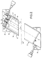
- Figure 2 is a section through transmitting and receiving heads of the detector shown in Figure 1;
- Figure 3 is a diagrammatic view illustrating an application of the detector in splice detecting apparatus;
- Figure 4 is a circuit diagram of the circuitry employed in the splice detecting apparatus;
- Figure 5 is a signal diagram showing the signals at various stages of the circuitry of Figure 4;
- Figure 6 is a diagrammatic view illustrating an application of the detector in edge detecting apparatus;
- Figure 7 is a circuit diagram of the circuitry employed in the edge detecting apparatus;
- Figure 8 is a signal diagram of the signals at various stages in the circuitry of Figure 7;
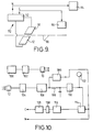
- Figure 9 is a diagrammatic view illustrating an application of the detector in a sheet gap detecting apparatus;
- Figure 10 is a circuit diagram of the circuitry employed in the sheet gap detecting apparatus; and
- Figure 11 is a signal diagram of the signals at various stages in the circuitry of Figure 10.
- Referring initially to Figures 1 and 2, a web detector according to the apparatus comprises an
ultrasonic transmitter 10 and anultrasonic receiver 12 mounted on asupport 14. Each of thetransmitter 10 and thereceiver 12 comprises ahead 16 carrying anultrasonic transducer 18, and theheads 16 are spaced from one another to allow aweb 20 of material to pass therebetween in use without contacting either of theheads 16. - The arrangement of the
support 14 and theheads 16 ensures that the ultrasonic beam between thetransducer 18 travels along an axis X-X which lies at an acute angle α relative to the plane of theweb 20 in use. As a result, sound waves reflected from the surface of theweb 20 are directed away from the path of the ultrasonic beam and out of the region where they might affect the level of energy transmitted between theultrasonic transducers 18. In the present instance, the angle α is approximately 60°, which is considered the optimum for the reduction of standing waves between theultrasonic transducers 18. However, it will be appreciated that other angles may be used so long as the axis of the ultrasonic beam is not nearly perpendicular to the web. The best results are expected with an angle in the range from 50° to 70°. - In order to achieve this desired arrangement of the
heads 16 and thetransducer 18, thesupport 14 comprises abracket 22 provided with a pair ofarms 24, which are located parallel to one another. Eacharm 24 has amounting plate 26 fixed thereto and, as shown, themounting plates 26 are fixed at different distances along thearms 24 to provide a respective mount for the associatedhead 16. Theheads 16 are attached to themounting plates 26 to face one another along the axis X-X. - The construction of both of the
heads 16 is the same, and therefore only one will be described with reference to Figure 2. As shown, thehead 16 comprises a rigidsquare housing 28 closed at its relatively outer end by awall 30 formed with acentral opening 32. Theultrasonic transducer 18 is mounted over theopening 32 by way of acarrier plate 34 secured to thewall 30 and asilicon rubber mount 36 carried by thecarrier plate 34. Thesilicon rubber mount 36 serves to absorb mechanical shock and vibrations, which might otherwise affect the output of theultrasonic transducer 18. - The interior of the
rigid housing 28 contains a sound absorbingfoam lining 38 filling the interior of thehousing 28 apart from anarrow passage 41 along the axis X-X providing a path for the ultrasonic beam. Embedded in thelining 38 is athin lead wall 40 as shown. Thehousing 28, together with thelining 38 and thelead wall 40, all terminate in asurface 42, which is disposed parallel to the plane of the web. The function of thefoam 38 and thelead wall 40 is firstly to limit the spread of the ultrasonic beam by absorbing sound waves which stray beyond thenarrow passage 41 to prevent such sound waves bouncing off extraneous objects and causing interference. Further, the form of thehousing 28, and lining 38 terminating in thesurface 42 will ensure that sound waves from the ultrasonic beam reflected from the surface of theweb 20 will gradually be absorbed by thefoam lining 38 as they bounce to and fro and will be attenuated. Conversely, of course, sound waves from outside the detector reflected from the surface of theweb 20 towards the ultrasonic beam will also be absorbed by thefoam lining 38. Finally, waves impinging on the exterior of thehousing 28 towards the ultrasonic beam will also be absorbed by thefoam lining 38. - The ultrasonic beam is thus substantially protected against interference and only sound waves passing along the axis X-X and transmitted across the
web 20 will contribute to web detection and any eventual measurement. This is particularly important because it means that web flap, which is a relatively common occurrence in a moving web, may cause reflections in the transmitted sound waves but will not affect the reading because waves set up by such flap are reflected away from the beam and gradually absorbed. - The two
ultrasonic transducers 18 are connected by means ofelectrical leads 50 to acontrol box 52, which is itself connected by afurther lead 54 to a power supply (not shown). The control box contains circuitry (described in greater detail below) for generating a 40 kHz sinusoidal signal for driving a piezo-ceramic crystal in thetransducer 18 in the ultrasonic transmitter. In use, the ultrasonic beam thus produced impinges on and passes through theweb 20 and is attenuated by an amount proportional to the density of the web in the region underneath thetransmitter 10. The attenuated beam is sensed by theultrasonic transducer 18 in thereceiver 12, which supplies an electrical output signal representative of the received ultrasonic beam. This output signal is processed by signal processing circuitry in thecontrol box 52 to provide a control output. - One application of the web detector as a splice detector is illustrated in Figure 3, and the circuitry in the
control box 52 in this instance is illustrated in Figure 4. - Referring first to Figure 3, the
web 20 is arranged first to pass through asplice detector 60, which is arranged approximately in the middle of theweb 20 in the lateral direction or at least substantially inset from the web edges. Downstream of thesplice detector 60, theweb 20 passes through a slit and choppingapparatus 62, which cuts theweb 20 both laterally and longitudinally to form individual sheets of material. In order to minimise waste when asplice 64 occurs in theweb 20, the slit and chopping apparatus is arranged to cut theweb 20 laterally immediately upstream and immediately downstream of thesplice 64 and to discard the row of sheets including thesplice 64. The integrity of all the remaining sheets is then unimpaired by blemishes due to thesplice 64. - For this purpose, the
splice detector 60 is arranged to detect the presence of thesplice 64, and thecontrol box 52 of thesplice detector 60 is arranged to generate a control output C after an appropriate delay for application to adrive 66. Thedrive 66 responds to the control output C by appropriate control of the cutter in the slit and choppingapparatus 62 to make slits on either side of thesplice 64 and then discard this region of theoriginal web 20. - Figure 4 shows the circuitry employed for generating the control output C, and Figure 5 is a signal diagram showing the signals at different stages of such circuitry.
- As shown in Figure 4, a
wave form generator 100 in the form of an oscillator produces a 40 kHz sinusoidal waveform, which is shown in Figure 5a. This waveform is supplied to adriver 102 which activates a piezo-ceramic crystal constituting thetransducer 18 in theultrasonic transmitter 10. - The transmitted ultrasonic beam passes through the
web 20 and is attenuated thereby by an amount dependent on the mass per unit length of theweb 20 and is received by thetransducer 18 in theultrasonic receiver 12. When a splice occurs, the attenuation of the transmitted signal increases temporarily so that there is a corresponding reduction in the signal output by thereceiver 12. This signal, after amplification in apreamplifier 104 is shown in Figure 5b. The output from thepreamplifier 104 is supplied through ahalfwave rectifier 106 and afilter 108 to anamplifier 110 to produce the signal shown in Figure 5c which is a single rectangular pulse. Ameter 112 monitors the level of the base signal. - The output from the
amplifier 110 is supplied by way of an automaticgain control circuit 114 to acomparator 116. The automatic gain control circuit monitors the amplitude of the base signal over a relatively long time period by comparison with the duration of the pulse shown in Figure C, and is thereby unaffected by the presence of the pulse. In the event that the signal level of the base signal changes due to a change in web material, then the automaticgain control circuit 114 makes a gain adjustment to bring the base signal to a predetermined level at its output. Consequently, the output of the automaticgain control circuit 114 is a base signal having a constant predetermined level, which is interrupted by a brief rectangular pulse whenever a splice occurs. - This output is supplied to the
comparator 116 where it is compared with a reference signal. The output of thecomparator 116 goes high whenever a rectangular pulse is detected and is supplied by way of a monostable 118 providing a delay to adriver 120. The output from thecomparator 116 is illustrated in Figure 5d. - The
driver 120 supplies the control output C, which is selectively in the form of a voltage pulse shown in Figure 5e or in the form of a relay activation signal as required. - In this application, the circuitry is required merely to generate an indication of the presence of the splice 72, for example in the form of the voltage pulse. It is not required to produce a measurement signal because the splice 72 is formed by butting two edges of web material and applying a tape of standard width and thickness to bridge the join, and so the thickness variation of the web at the splice is already known. In an alternative form of splice detector, of course, the signal processing circuitry could be adapted to provide a measurement signal indicative of the thickness of the splice and/or the width of the splice.
- An application of the detector as an
edge position detector 80 is illustrated in Figure 6 with the signal processing circuitry employed in this instance in thecontrol box 52 being shown in Figure 7. - Figure 6 differs from Figure 3 in that the
edge position detector 80 is situated adjacent an edge of theweb 20 to detect and measure variations in the position of this edge and generate a corresponding control output C. The control output C is then applied to asteering frame 82 located for steering theweb 20 and controlling its lateral position generally or through a subsequent work station. For this purpose, theedge detector 80 applies the control output C to acontrol arm 84 of thesteering frame 82 which in turn adjusts a steeringroller 86 as necessary to reposition the web laterally to correct any wander. Otheredge position detectors 80 and associated steering frames 82 will also be situated at intervals along the path of the web. Indeed edgeposition detectors 80 may also be employed alone for monitoring the position of the edge of the web for other reasons for example to detect the alignment of the web following a join. - Turning to Figures 7 and 8, the signal processing circuitry for this application and the corresponding signals will now be described.
- A wave form generator in the form of an
oscillator 200 generates a 40 kHz sinusoidal signal as before, which is shown in Figure 8a, and adriver 202 is responsive to this signal to drive the piezo-ceramic crystal constituting thetransducer 18 of theultrasonic transmitter 10. The ultrasonic beam is transmitted past the edge of theweb 20 and is attenuated by an amount which is dependent on the degree to which the edge of theweb 20 covers or obstructs a part of the beam. The attenuated beam is picked up by thetransducer 18 in theultrasonic receiver 12 and supplied to apreamplifier 203. The received signal, however, is affected not only by the position of the edge of theweb 20 but also by the ambient temperature, and in order to compensate for this atemperature probe 204 measures the ambient temperature and supplies a temperature signal to thepreamplifier 203 to control the gain of this amplifier. The output of theamplifier 203 is illustrated in Figure 8b and show how the envelope of the received signal varies continuously with variations in the position of the edge of theweb 20. - The output from the
preamplifier 203 is supplied by way of ahalfwave rectifier 206 and afilter 208 to an amplifier 210. The amplifier 210 also has an offsetcontrol input 212 and again control input 214 and is precalibrated such that a web neutral position corresponding with the edge of theweb 20 covering one half of the area of the transmitted ultrasonic beam is represented by an output from the amplifier 210 of 0 volts. The overall output from the amplifier 210 is illustrated in Figure 8C and it will be seen that this is a continuously varying signal, which crosses the 0 volt axis on each occasion that the edge of theweb 20 passes through the neutral position. - The voltage output from the amplifier 210 is supplied to a voltage to
current convertor 216 to supply a control output in the form of a current, since this is the form of output required to drive thesteering frame 82. - Although the above description has been confined to the use of the invention in relation to web detection, and particularly the detection of a splice in a web or the detection of the edge position of a web, the invention can equally well be applied to the detection of individual sheets, for example to the detection of spaces between sheets or an edge position of each sheet.
- A further application of the detector as a gap detector for detecting the spaces between individual sheets of material will now be described with reference to Figures 9 to 11.
- Referring to Figure 9, individual sheets of
material 90 are arranged to pass through thegap detector 92, which is arranged approximately in the middle of the path of thesheets 90. Thegap detector 92 detects firstly the presence of splices in the individual sheets and generates a corresponding control output C as in the case of the apparatus shown in Figure 4, and secondly the presence of each gap between the individual sheets and generates a further output N in the form of a corresponding pulse. The output C is applied to acontrol gate 94 of a packing machine for causing the gate to discard sheets including a splice, and the output N may for example be applied to acounter 96 for counting the sheets being packed. - Figure 10 shows the circuitry employed for generating the control outputs C and N in this instance, and Figure 11 is a signal diagram showing the signals at certain stages of the circuitry. The circuitry shown in Figure 10 is in many respects similar to the circuitry of Figure 4 employed in the splice detecting apparatus and like parts are designated by the same reference numerals and will not be described in detail. Likewise, the signals occurring in the Figure 10 circuitry and corresponding to those shown in Figure 5 are omitted in Figure 11 and will not be described.
- As shown in Figure 10, the
wave form generator 100 produces the 40 kHz sinusoidal wave form, which is shown in Figure 11a and which is supplied to thedriver 102 for driving a piezo-ceramic crystal constituting thetransducer 18 in theultrasonic transmitter 10. - The transmitted ultrasonic beam passes through the
sheets 90 and is attenuated thereby and is received by thetransducer 18 in theultrasonic receiver 12. When a splice occurs, this is detected as described above and the control output C is produced. When a gap occurs, there is temporarily no attenuation and the signal output by thereceiver 12 increases correspondingly. This signal, after amplification in thepreamplifier 104 is shown in Figure 11b. The output from theamplifier 104 is supplied by way of thehalfwave rectifier 106 and filter 108 to theamplifier 110 to produce the signal shown in Figure 11c, which is a single rectangular pulse of large and undefined amplitude. This undefined pulse is supplied to the automaticgain control circuit 114 and, in the absence of appropriate measures, would upset the normal functioning of thecircuit 114 for detecting changes in the material of the individual sheets. - Therefore, in order to prevent the
circuit 114 from reacting incorrectly to a gap between the sheets, a clamp and blank signal of known amplitude shown in Figure 11d is derived from the output of thehalfwave rectifier 106 by way of a highlevel trip amplifier 300. This clamp and blank signal is applied to the automaticgain control circuit 114 to cause thecircuit 114 to blank out the unwanted part of the input constituting the undefined pulse and to hold its output in the condition it was in immediately preceding the arrival of the undefined pulse. Consequently, the automaticgain control circuit 114 is enabled to monitor the amplitude of the base signal and make a suitable gain adjustment when changes in the material of the individual sheets are detected, but without being affected by the change in signal level produced by gaps between the sheets. - The rectangular pulses generated by the high
level trip amplifier 300 in response to such gaps in addition to being supplied to the automaticgain control circuit 114 are also supplied as the further output N as shown and may be used for counting the numbers of sheets to be packed.
Claims (13)
- A sheet material detector comprising an ultrasonic transmitter and an ultrasonic receiver spaced from one another to permit the passage of sheet material therebetween, means for supporting the transmitter and the receiver respectively to transmit and receive the ultrasonic beam along an axis directed at an acute angle to the plane of the sheet material in use, a shield for protecting the ultrasonic beam from the effects of stray sound waves, and output signal means responsive to the received ultrasonic beam for generating an output signal.
- A detector according to claim 1 in which the axis of the ultrasonic beam is in the range from 50° to 70° relative to the plane of the sheet material in use.
- A detector according to claim 2 in which the axis of the ultrasonic beam is at 60° relative to the plane of the sheet material in use.
- A detector according to any preceding claim in which the shield is arranged to limit the spread of the ultrasonic beam for preventing the reflection of sound waves from extraneous surfaces.
- A detector according to any preceding claim in which the shield is arranged to absorb stray sound waves caused by reflection at the surface of the sheet material.
- A detector according to any preceding claim in which the shield comprises a sound absorbing material.
- A detector according to claim 6 in which the shield comprises sound absorbing foam.
- A detector according to claim 6 or 7 in which the shield includes at least one lead wall embedded in the sound absorbing material.
- A detector according to any preceding claim in which the shield comprises a first hood constituting a part of the transmitter and a second hood constituting a part of the receiver.
- A detector according to claim 9 in which each hood terminates in a surface lying parallel to the plane of the sheet material in use.
- Splice detecting apparatus comprising a sheet material detector according to any preceding claim, and signal processing means responsive to the output signal for generating a splice indication output indicative of the presence of a splice in the sheet material.
- Edge detecting apparatus comprising a sheet material detector according to any of claims 1 to 10, and signal processing means responsive to the output signal for generating an edge position signal representing the position of an edge of the sheet material.
- Gap detecting apparatus comprising a sheet material detector according to any of claims 1 to 10, and signal processing means responsive to the output signal for generating a gap signal indicative of the presence of a gap between sheets of the sheet material.
Applications Claiming Priority (2)
| Application Number | Priority Date | Filing Date | Title |
|---|---|---|---|
| GB9508654 | 1995-04-28 | ||
| GBGB9508654.2A GB9508654D0 (en) | 1995-04-28 | 1995-04-28 | Sheet material detector |
Publications (1)
| Publication Number | Publication Date |
|---|---|
| EP0740154A1 true EP0740154A1 (en) | 1996-10-30 |
Family
ID=10773678
Family Applications (1)
| Application Number | Title | Priority Date | Filing Date |
|---|---|---|---|
| EP96201127A Ceased EP0740154A1 (en) | 1995-04-28 | 1996-04-25 | Sheet material detector |
Country Status (4)
| Country | Link |
|---|---|
| US (1) | US5661243A (en) |
| EP (1) | EP0740154A1 (en) |
| JP (1) | JPH0921790A (en) |
| GB (1) | GB9508654D0 (en) |
Cited By (6)
| Publication number | Priority date | Publication date | Assignee | Title |
|---|---|---|---|---|
| EP0829754A1 (en) * | 1996-09-17 | 1998-03-18 | Konica Corporation | Ultrasonic wave splicing device |
| WO2000019191A1 (en) * | 1998-09-28 | 2000-04-06 | Giesecke & Devrient Gmbh | Device for examining sheet-like articles using ultrasound |
| EP1562043A1 (en) * | 2004-02-05 | 2005-08-10 | Metso Paper, Inc. | A method and apparatus for determining the lateral position of a web or fabric edge |
| WO2007017663A1 (en) * | 2005-08-10 | 2007-02-15 | De La Rue International Limited | Ultrasonic document inspection system |
| WO2008077566A2 (en) | 2006-12-22 | 2008-07-03 | Giesecke & Devrient Gmbh | Device for outputting and/or receiving ultrasound and ultrasound sensor for inspecting a valuable document |
| CN102542656A (en) * | 2011-12-31 | 2012-07-04 | 北京中科金财科技股份有限公司 | Bill authenticity identification equipment and method based on ultrasound excitation material features |
Families Citing this family (6)
| Publication number | Priority date | Publication date | Assignee | Title |
|---|---|---|---|---|
| US6732587B2 (en) | 2002-02-06 | 2004-05-11 | Lockheed Martin Corporation | System and method for classification of defects in a manufactured object |
| US7089795B2 (en) * | 2003-10-06 | 2006-08-15 | Bray Don E | Ultrasonic characterization of polymeric containers |
| US7415881B2 (en) * | 2004-08-19 | 2008-08-26 | Fife Corporation | Ultrasonic sensor system for web-guiding apparatus |
| DE102005026200A1 (en) | 2005-06-07 | 2006-12-21 | Pepperl + Fuchs Gmbh | Detection and device for the detection of recording media |
| KR20090084912A (en) * | 2007-02-28 | 2009-08-05 | 가부시키가이샤 무라타 세이사쿠쇼 | Medium fatigue detection device and medium fatigue detection method |
| CN110298289B (en) * | 2019-06-24 | 2021-11-02 | Oppo广东移动通信有限公司 | Material identification method, device, storage medium and electronic device |
Citations (4)
| Publication number | Priority date | Publication date | Assignee | Title |
|---|---|---|---|---|
| EP0098115A1 (en) * | 1982-06-28 | 1984-01-11 | De La Rue Systems Limited | Detecting the condition of a sheet or web |
| EP0167010A2 (en) * | 1984-07-04 | 1986-01-08 | GAO Gesellschaft für Automation und Organisation mbH | Apparatus for measuring the surface weight of sheet material |
| US4901577A (en) * | 1988-04-28 | 1990-02-20 | World Color Press, Inc. | Apparatus for detecting splices in the web of a printing press |
| WO1995011453A1 (en) * | 1993-10-22 | 1995-04-27 | Amcor Limited | Strength determination of sheet materials by ultrasonic testing |
Family Cites Families (8)
| Publication number | Priority date | Publication date | Assignee | Title |
|---|---|---|---|---|
| GB710124A (en) * | 1950-09-22 | 1954-06-09 | British Thomson Houston Co Ltd | Improvements in and relating to methods of measuring thickness or density of thin sheets |
| US3485087A (en) * | 1965-10-05 | 1969-12-23 | Branson Instr | Ultrasonic inspection apparatus |
| GB1290978A (en) * | 1970-09-02 | 1972-09-27 | ||
| JPS5253105Y2 (en) * | 1973-04-27 | 1977-12-02 | ||
| US4437332A (en) * | 1982-09-30 | 1984-03-20 | Krautkramer-Branson, Inc. | Ultrasonic thickness measuring instrument |
| US4545248A (en) * | 1983-06-16 | 1985-10-08 | Kabushiki Kaisha Tokyo Keiki | Ultrasonic thickness gauge |
| US4594897A (en) * | 1984-01-27 | 1986-06-17 | Bethlehem Steel Corporation | Inspection of the internal portion of objects using ultrasonics |
| US5488867A (en) * | 1992-08-21 | 1996-02-06 | Xecutek Corporation | Strip measuring and centering system |
-
1995
- 1995-04-28 GB GBGB9508654.2A patent/GB9508654D0/en active Pending
-
1996
- 1996-03-13 US US08/615,059 patent/US5661243A/en not_active Expired - Fee Related
- 1996-04-25 EP EP96201127A patent/EP0740154A1/en not_active Ceased
- 1996-04-26 JP JP8107668A patent/JPH0921790A/en active Pending
Patent Citations (4)
| Publication number | Priority date | Publication date | Assignee | Title |
|---|---|---|---|---|
| EP0098115A1 (en) * | 1982-06-28 | 1984-01-11 | De La Rue Systems Limited | Detecting the condition of a sheet or web |
| EP0167010A2 (en) * | 1984-07-04 | 1986-01-08 | GAO Gesellschaft für Automation und Organisation mbH | Apparatus for measuring the surface weight of sheet material |
| US4901577A (en) * | 1988-04-28 | 1990-02-20 | World Color Press, Inc. | Apparatus for detecting splices in the web of a printing press |
| WO1995011453A1 (en) * | 1993-10-22 | 1995-04-27 | Amcor Limited | Strength determination of sheet materials by ultrasonic testing |
Cited By (15)
| Publication number | Priority date | Publication date | Assignee | Title |
|---|---|---|---|---|
| EP0829754A1 (en) * | 1996-09-17 | 1998-03-18 | Konica Corporation | Ultrasonic wave splicing device |
| WO2000019191A1 (en) * | 1998-09-28 | 2000-04-06 | Giesecke & Devrient Gmbh | Device for examining sheet-like articles using ultrasound |
| EP1562043A1 (en) * | 2004-02-05 | 2005-08-10 | Metso Paper, Inc. | A method and apparatus for determining the lateral position of a web or fabric edge |
| EP2090885A1 (en) * | 2005-08-10 | 2009-08-19 | De La Rue International Limited | Ultrasonic document inspection system |
| WO2007017663A1 (en) * | 2005-08-10 | 2007-02-15 | De La Rue International Limited | Ultrasonic document inspection system |
| AU2006277762B2 (en) * | 2005-08-10 | 2010-03-04 | De La Rue International Limited | Ultrasonic document inspection system |
| US7748274B2 (en) | 2005-08-10 | 2010-07-06 | De La Rue International Limited | Document inspection system |
| AU2010200220B2 (en) * | 2005-08-10 | 2012-07-19 | De La Rue International Limited | Ultrasonic Document Inspection System |
| WO2008077566A2 (en) | 2006-12-22 | 2008-07-03 | Giesecke & Devrient Gmbh | Device for outputting and/or receiving ultrasound and ultrasound sensor for inspecting a valuable document |
| WO2008077566A3 (en) * | 2006-12-22 | 2008-09-12 | Giesecke & Devrient Gmbh | Device for outputting and/or receiving ultrasound and ultrasound sensor for inspecting a valuable document |
| RU2444010C2 (en) * | 2006-12-22 | 2012-02-27 | Гизеке Унд Девриент Гмбх | Apparatus for emitting and/or receiving ultrasound and ultrasonic sensor for analysing valuable document |
| CN101611425B (en) * | 2006-12-22 | 2012-06-20 | 德国捷德有限公司 | Devices for emitting and/or receiving ultrasonic waves and ultrasonic sensors for inspecting securities |
| US8230742B2 (en) | 2006-12-22 | 2012-07-31 | Giesecke & Devrient Gmbh | Device for outputting and/or receiving ultrasound and ultrasound sensor for inspecting a valuable document |
| US9194845B2 (en) | 2006-12-22 | 2015-11-24 | Giesecke & Devrient Gmbh | Device for outputting and/or receiving ultrasound and ultrasound sensor for inspecting a valuable document |
| CN102542656A (en) * | 2011-12-31 | 2012-07-04 | 北京中科金财科技股份有限公司 | Bill authenticity identification equipment and method based on ultrasound excitation material features |
Also Published As
| Publication number | Publication date |
|---|---|
| GB9508654D0 (en) | 1995-06-14 |
| US5661243A (en) | 1997-08-26 |
| JPH0921790A (en) | 1997-01-21 |
Similar Documents
| Publication | Publication Date | Title |
|---|---|---|
| US5661243A (en) | Sheet material detector | |
| US5486063A (en) | Method and apparatus for sensing the length of label or tag media by detecting changes in relative thickness | |
| CA1299889C (en) | Method and apparatus for noncontacting tension measurement in a flat foil and especially in a paper web | |
| US5126946A (en) | Ultrasonic edge detector | |
| US20010042956A1 (en) | Double feed detection method and device | |
| US4901292A (en) | Method for the position detection of the strip edge of a material web | |
| JPH0317706B2 (en) | ||
| US8201453B2 (en) | Medium fatigue detection apparatus and medium fatigue detection method | |
| US20110226061A1 (en) | Sheet processing device | |
| JPH0614310B2 (en) | Coordinate input device | |
| US5565627A (en) | Ultrasonic edge detector and control system | |
| JP3993366B2 (en) | Foreign matter detection device for paper sheets | |
| EP0419115B1 (en) | Pass-line independent web measuring method and apparatus | |
| EP0398428B1 (en) | Probe for ultrasonic microscope | |
| JPH0354409A (en) | ultrasonic seam detector | |
| US5190789A (en) | Ultrasonic monitoring of a freely flowing curtain of coating material | |
| JP2891119B2 (en) | Glue inspection device | |
| US4513404A (en) | Acoustic reflectometer for sheet feed sensing | |
| US4774840A (en) | Detector for rod-like articles | |
| US5488867A (en) | Strip measuring and centering system | |
| JP2004061120A (en) | Ultrasonic distance measuring sensor | |
| JP3663768B2 (en) | Steel length measuring device | |
| JP2588838Y2 (en) | Textile unevenness defect detection device | |
| JPH0437924B2 (en) | ||
| JPH02179472A (en) | Ultrasonic wave seam detector |
Legal Events
| Date | Code | Title | Description |
|---|---|---|---|
| PUAI | Public reference made under article 153(3) epc to a published international application that has entered the european phase |
Free format text: ORIGINAL CODE: 0009012 |
|
| AK | Designated contracting states |
Kind code of ref document: A1 Designated state(s): DE FR GB NL |
|
| 17P | Request for examination filed |
Effective date: 19970324 |
|
| 17Q | First examination report despatched |
Effective date: 20010117 |
|
| RAP1 | Party data changed (applicant data changed or rights of an application transferred) |
Owner name: EASTMAN KODAK COMPANY |
|
| GRAG | Despatch of communication of intention to grant |
Free format text: ORIGINAL CODE: EPIDOS AGRA |
|
| STAA | Information on the status of an ep patent application or granted ep patent |
Free format text: STATUS: THE APPLICATION HAS BEEN REFUSED |
|
| 18R | Application refused |
Effective date: 20020203 |