EP0739703A1 - Bottom shape of reuseable PET containers - Google Patents
Bottom shape of reuseable PET containers Download PDFInfo
- Publication number
- EP0739703A1 EP0739703A1 EP95106387A EP95106387A EP0739703A1 EP 0739703 A1 EP0739703 A1 EP 0739703A1 EP 95106387 A EP95106387 A EP 95106387A EP 95106387 A EP95106387 A EP 95106387A EP 0739703 A1 EP0739703 A1 EP 0739703A1
- Authority
- EP
- European Patent Office
- Prior art keywords
- base
- insert
- truncated cone
- bottle
- floor
- Prior art date
- Legal status (The legal status is an assumption and is not a legal conclusion. Google has not performed a legal analysis and makes no representation as to the accuracy of the status listed.)
- Granted
Links
Images
Classifications
-
- B—PERFORMING OPERATIONS; TRANSPORTING
- B29—WORKING OF PLASTICS; WORKING OF SUBSTANCES IN A PLASTIC STATE IN GENERAL
- B29C—SHAPING OR JOINING OF PLASTICS; SHAPING OF MATERIAL IN A PLASTIC STATE, NOT OTHERWISE PROVIDED FOR; AFTER-TREATMENT OF THE SHAPED PRODUCTS, e.g. REPAIRING
- B29C49/00—Blow-moulding, i.e. blowing a preform or parison to a desired shape within a mould; Apparatus therefor
- B29C49/18—Blow-moulding, i.e. blowing a preform or parison to a desired shape within a mould; Apparatus therefor using several blowing steps
-
- B—PERFORMING OPERATIONS; TRANSPORTING
- B29—WORKING OF PLASTICS; WORKING OF SUBSTANCES IN A PLASTIC STATE IN GENERAL
- B29C—SHAPING OR JOINING OF PLASTICS; SHAPING OF MATERIAL IN A PLASTIC STATE, NOT OTHERWISE PROVIDED FOR; AFTER-TREATMENT OF THE SHAPED PRODUCTS, e.g. REPAIRING
- B29C2949/00—Indexing scheme relating to blow-moulding
- B29C2949/07—Preforms or parisons characterised by their configuration
- B29C2949/0715—Preforms or parisons characterised by their configuration the preform having one end closed
-
- B—PERFORMING OPERATIONS; TRANSPORTING
- B29—WORKING OF PLASTICS; WORKING OF SUBSTANCES IN A PLASTIC STATE IN GENERAL
- B29C—SHAPING OR JOINING OF PLASTICS; SHAPING OF MATERIAL IN A PLASTIC STATE, NOT OTHERWISE PROVIDED FOR; AFTER-TREATMENT OF THE SHAPED PRODUCTS, e.g. REPAIRING
- B29C49/00—Blow-moulding, i.e. blowing a preform or parison to a desired shape within a mould; Apparatus therefor
- B29C49/02—Combined blow-moulding and manufacture of the preform or the parison
- B29C49/06—Injection blow-moulding
-
- B—PERFORMING OPERATIONS; TRANSPORTING
- B29—WORKING OF PLASTICS; WORKING OF SUBSTANCES IN A PLASTIC STATE IN GENERAL
- B29K—INDEXING SCHEME ASSOCIATED WITH SUBCLASSES B29B, B29C OR B29D, RELATING TO MOULDING MATERIALS OR TO MATERIALS FOR MOULDS, REINFORCEMENTS, FILLERS OR PREFORMED PARTS, e.g. INSERTS
- B29K2067/00—Use of polyesters or derivatives thereof, as moulding material
Definitions
- the invention is concerned with the design of floor surfaces - in this technical field called "floor geometry" - on plastic bottles which are formed from a preform (an injection molded blank) in two blow moldings (applying high pressure). These plastic bottles are hot washable, so their geometry must not change noticeably at a temperature of above 60 ° C or 75 ° C.
- the temperature mentioned relates to the temperature of the washing liquid at which the bottles must remain thermally stable; slight geometric deformations that do not impair mechanical stability or stability can be tolerated.
- the plastic bottles are made of PET, which forms the bottle wall in one or more layers.
- the bottles must stand securely in the floor area and be stable against internal pressure. This stability affects the stability of use.
- Another stability is mentioned above and relates to the temperature stability when washing the bottle hot, that is, the prerequisite for reusability.
- An additional property now comes to the bottom area, it must be "inspectable”, with which the person skilled in this technical field understands the unrestricted visual view of the bottom area in the bottle axis. This floor inspection must not be influenced by shadows and other light refractions, because then a visual inspection of the empty bottle using a camera or eye is not possible.
- the object of the invention is therefore to provide a base geometry on plastic bottles that is both thermally stable and has no shadow effects, that is to say is fully inspectable for residual lye (from cleaning) or foreign bodies in the container safely and reliably, that is completely, to be able to recognize before the bottle is filled.
- the invention does not want to accept any restrictions on the bottom diameter with regard to the ability to inspect, as is the case in the prior art, for example, in that bottles have an outwardly directed, in Main hemispherical base geometry obtained and placed in a plastic support ring by extensive retraction, so that they have a safe footprint.
- the above object is achieved by the invention in three forms, namely by using a truncated cone-shaped base insert (claim 1) or by a manufacturing process in which a preform in a first blow molding receives a truncated cone-shaped bottle base which has a wavy cross-section after removal (claim 9) or with a device for performing the above-mentioned method, in which a truncated cone base is provided in a first blow mold and a second blow mold has a substantially dome-shaped base (claim 11).
- the substantially dome-shaped base of claim 11 is adapted in shape to the base geometry of the bottle taken out of the first blow mold (claim 16), so that in the second blow molding the base changes only insignificantly in its geometry, only in its basic form already existing forms is clarified.
- Identity of form does not mean dimension identity (from the dimensions), but design identity (relative location of the partial forms and the partial forms themselves).
- the basic architecture is given to the floor after it has been removed from the truncated cone-shaped floor insert or after shrinking, which causes it to detach from this insert.
- the wave structure resulting after the removal or shrinkage in the Floor architecture is already the floor design that allows full visual inspection without shadow formation while maintaining temperature stability.
- This base geometry is undulating in cross section, that is to say it has a first curvature r 'directed towards the inside of the bottle, which is essentially spherical segment-shaped, and a second, outwardly directed curvature r''which adjoins the first curvature r'.
- the base contact ring Radially outside of the first curvature, the base contact ring is formed, on which the bottle can stand securely.
- the surprising effect of the invention is justified by the fact that a "memory effect" is used in the linear region of the base, which automatically forms the base in a wave shape after removal of the truncated cone supporting it, the base becoming essentially free of internal stress.
- this already undulating base can be made clearer if it is blow molded again on a second blow mold insert.
- This blow mold insert has essentially the same design as the bottom, which forms after the first blow molding and removal from the truncated cone insert, so that only slight deformations occur (claim 16).
- One of them can be an arched dome, which corresponds to the upper plateau area of the truncated cone (claim 8) - shown in the bottle bottom (claim 17,7).
- the second floor insert is also designed accordingly, whereas the first floor insert with its outer surface for the first blow molding is essentially linear (or: flat).
- the angle at which the truncated cone extends with its lateral surface can be between 40 ° and 70 °, advantageously it runs below 60 ° (claim 4.5).
- the frustoconical bottom of the first blow mold can be designed as an insert (claim 1), but it can also be designed in one piece with the blow mold, the bottom of which it forms (claim 1, claim 11).
- the two-stage blow molding process which is clearly mentioned, relates to the preform, which in a first blow molding step is molded in a first mold under pressure into an intermediate container.
- the intermediate container can be significantly larger than the final target container.
- the intermediate container is shrunk to a size below that which is ultimately intended.
- the shrunk intermediate container gets its final shape. Nonetheless, the floor remains mathematically similar in its undulating shape, which includes a change in size caused by shrinking, but maintains a design identity.
- Both blow molding steps can be designed in such a way that the bottles or intermediate containers for each blow molding are arranged detachably on one storage wheel each (claims 13, 14), so that they can be easily shaped and continuously cooled.
- the material savings are particularly pronounced if the invention allows the bottoms of plastic bottles, which were previously thicker, to be made thinner, while still maintaining thermal stability in the bottom area.
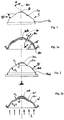
- an outer surface 1a is drawn at an angle ⁇ with respect to the vertical (the bottle axis 100), which extends essentially straight.
- the mold bottom insert 1 contains at the inner end of the straight surface line a flat plateau 1c which runs horizontally.
- a ring constriction section 1b is shown, which is used to implement the ring contact surface 10r.
- a first blow molding causes the bottom section of the preform to be pressed onto the truncated cone bottom 1 of FIG converts into a floor geometry independently and without external influences, as shown in FIG. 1a.
- the geometry shows an architecture which is wavy in cross-section, in which a first, outer curvature 10 'with a radius r' is formed, which is formed inwardly by the standing bead 10r or the ring contact surface 10r.
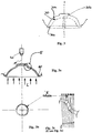
- FIG. 2 shows a second base insert 20, the architecture of which is closely adapted to the resulting base design of the bottle, which is shown in FIG. 1a.
- two oppositely directed radii r1 and r2 are also present, which define a first curved region 20b and an oppositely curved second region 20a, the latter lying radially further inward than the former.
- the inner curved region 20a leads into a slightly domed, stepped dome 20c, which is adapted in its radial extent to the plateau 10k of FIG. 1a.
- the outer curved region 20b which has the shape of a spherical layer, leads into the molded part section, which defines the inner region of the uprising bead 10r.
- FIG. 2a The result of the second stretch blow molding process (blow molding process) is shown in FIG. 2a , where the bottom geometry which was already established in FIG. 1a is more clearly defined, but is not significantly changed.
- FIGS. 1a, 2a are essentially "similar" (in the mathematical sense).
- the last-mentioned floor geometry has an unrestricted ability to inspect, which is indicated by the vertically drawn arrows L - parallel to the central axis 100.
- FIGS. 3b, 3c The shadow formation S of a prior art is illustrated in FIGS. 3b, 3c , and the area in FIG. 3a that causes this shadow area S — represented as an annular darkening zone in FIG. 3b — is also shown.
- a camera 40 which has a lens which is designed such that the entire base area is imaged within the contact ring 10r, would show the ring according to FIG. 3b as an image. In this area, only a limited visual inspection - a limited possibility of inspection - is justified, so that this floor area does not achieve what can be achieved with the floor area according to FIG. 2b only with the aid of a truncated cone-shaped floor 1 according to FIG.
- FIG. 3 The counterpart to FIG. 1 is depicted in FIG. 3 only for purposes of illustration, with which in the prior art the base region is formed in the first blow molding step, which leads to the base geometry in accordance with FIG. 3a in the second blow molding step.
- a dominating spherical segment 30a can be seen there, which occupies almost the entire floor area and gives the floor an architecture that is only curved inwards within the standing bead 30c or 10r.
- This dome-shaped structure is first converted into a geometry with a second floor insert (not shown here), which offers thermal stability, mechanical strength but only limited, not optimal inspection capability.
- the angle ⁇ shown in FIG. 1, which corresponds to the vertical inclination of the lateral surface 1a of the truncated cone, is approximately 60 °; it can easily be changed upwards or downwards, whereby the surprising and independent undulating deformation of the base detached from the truncated cone is still evident.
- the independent deformation - achieved via the "memory effect" - does not take place outside the areas mentioned.
Abstract
Description
Die Erfindung befaßt sich mit der Gestaltung von Bodenflächen - in diesem technischen Gebiet "Bodengeometrie" genannt - an Kunststoff-Flaschen, die aus einer Preform (einem spritzgußgeformten Rohling) in zwei Blasformungen (Einbringen von hohem Druck) geformt werden. Diese Kunststoff-Flaschen sind heiß waschbar, dürfen sich also bei einer Temperatur von oberhalb 60°C oder 75°C von ihrer Geometrie her nicht spürbar verändern. Die genannte Temperatur betrifft die Temperatur der Waschflüssigkeit, bei der die Flaschen thermisch stabil bleiben müssen; geringe geometrische Verformungen, die die mechanische Stabilität oder die Standfestigkeit nicht beeinträchtigen, können toleriert werden.The invention is concerned with the design of floor surfaces - in this technical field called "floor geometry" - on plastic bottles which are formed from a preform (an injection molded blank) in two blow moldings (applying high pressure). These plastic bottles are hot washable, so their geometry must not change noticeably at a temperature of above 60 ° C or 75 ° C. The temperature mentioned relates to the temperature of the washing liquid at which the bottles must remain thermally stable; slight geometric deformations that do not impair mechanical stability or stability can be tolerated.
Zumeist werden die Kunststoff-Flaschen aus PET hergestellt, das in einer oder mehreren Schichten die Flaschenwandung bildet. Im Bodenbereich müssen die Flaschen sicher stehen und stabil gegen inneren Druck sein. Diese Stabilität betrifft die Gebrauchs-Stabilität. Eine andere Stabilität ist oben erwähnt und betrifft die Temperatur-Stabilität beim heißen Waschen der Flasche, also die Voraussetzung der Wiederverwendbarkeit. Eine zusätzliche Eigenschaft kommt nun dem Bodenbereich zu, er muß "inspektionsfähig" sein, womit der Fachmann in diesem technischen Gebiet den uneingeschränkten optischen Einblick in den Bodenbereich in Flaschenachse versteht. Diese Bodeninspektion darf nicht beeinflußt sein von Schatten und anderen Lichtbrechungen, weil dann eine visuelle Kontrolle der leeren Flasche mittels Kamera oder Auge nicht möglich ist.Most of the time, the plastic bottles are made of PET, which forms the bottle wall in one or more layers. The bottles must stand securely in the floor area and be stable against internal pressure. This stability affects the stability of use. Another stability is mentioned above and relates to the temperature stability when washing the bottle hot, that is, the prerequisite for reusability. An additional property now comes to the bottom area, it must be "inspectable", with which the person skilled in this technical field understands the unrestricted visual view of the bottom area in the bottle axis. This floor inspection must not be influenced by shadows and other light refractions, because then a visual inspection of the empty bottle using a camera or eye is not possible.
Aufgabe der Erfindung ist es deshalb, eine Bodengeometrie an Kunststoff-Flaschen zur Verfügung zu stellen, die sowohl thermisch stabil ist als auch ohne Schatteneffekte ist, also vollumfänglich inspektionsfähig ist, um Restlauge (von der Reinigung) oder Fremdkörper im Behälter sicher und zuverlässig, also vollumfänglich, erkennen zu können, bevor die Flasche befüllt wird. Die Erfindung möchte dabei hinsichtlich der Inspektionsfähigkeit keine Einschränkungen des Bodendurchmessers in Kauf nehmen, wie das im Stand der Technik z.B. dadurch der Fall ist, daß Flaschen eine nach außen gerichtete, im wesentlichen halbkugelförmige Bodengeometrie erhalten und durch umfängliches Einziehen in einen Kunststoff-Stützring gestellt werden, damit sie eine sichere Aufstandsfläche haben. The object of the invention is therefore to provide a base geometry on plastic bottles that is both thermally stable and has no shadow effects, that is to say is fully inspectable for residual lye (from cleaning) or foreign bodies in the container safely and reliably, that is completely, to be able to recognize before the bottle is filled. The invention does not want to accept any restrictions on the bottom diameter with regard to the ability to inspect, as is the case in the prior art, for example, in that bottles have an outwardly directed, in Main hemispherical base geometry obtained and placed in a plastic support ring by extensive retraction, so that they have a safe footprint.
Bei dieser Lösung wird die Inspektionsfähigkeit verringert, weil der die radiale Einziehung des Flaschenunterteils verursachende Kunststoff-Standfuß optisch nicht durchlässig ist. Funktionell weist er eine solche Geometrie auf, die - selbst bei seiner optisch durchlässsigen Gestaltung - eine schattenfreie, vollumfängliche Inspektion durch den Boden im Leerzustand nicht erlauben würde.With this solution, the ability to inspect is reduced because the plastic base that causes the radial retraction of the lower part of the bottle is not optically transparent. Functionally, it has such a geometry that - even with its optically permeable design - would not allow a shadow-free, comprehensive inspection through the floor when empty.
Die vorgenannte Aufgabe löst die Erfindung dreigestaltig, namentlich durch die Verwendung eines kegelstumpfförmigen Bodeneinsatzes (Anspruch 1) oder durch ein Herstellverfahren, bei dem eine Preform in einer ersten Blasformung einen kegelstumpfförmigen Flaschenboden erhält, der nach Herausnehmen einen wellenförmigen Querschnitt aufweist (Anspruch 9) oder mit einer Vorrichtung zur Durchführung des erwähnten Verfahrens, in der ein Kegelstumpf-Boden in einer ersten Blasform vorgesehen ist und eine zweite Blasform einen im wesentlichen kuppelförmigen Boden aufweist (Anspruch 11).The above object is achieved by the invention in three forms, namely by using a truncated cone-shaped base insert (claim 1) or by a manufacturing process in which a preform in a first blow molding receives a truncated cone-shaped bottle base which has a wavy cross-section after removal (claim 9) or with a device for performing the above-mentioned method, in which a truncated cone base is provided in a first blow mold and a second blow mold has a substantially dome-shaped base (claim 11).
Der im wesentlichen kuppelförmige Boden des Anspruchs 11 ist von der Form her an die Bodengeometrie der aus der ersten Blasform herausgenommenen Flasche angepaßt (Anspruch 16), so daß in der zweiten Blasformung der Boden sich nur noch unwesentlich in seiner Geometrie verändert, lediglich in seinen grundsätzlich schon vorhandenen Formen verdeutlicht wird. Identität der Form heißt aber nicht Dimensionsidentität (von den Maßen her), sondern Gestaltungsidentität (relativer Ort der Teil-Formen und die Teil-Formen selbst).The substantially dome-shaped base of
Die grundsätzliche Architektur erhält der Boden nach dem Abnehmen vom kegelstumpfförmigen Bodeneinsatz bzw. nach dem Schrumpfen, der ein Ablösen von diesem Einsatz bewirkt. Überraschend hat sich dabei herausgestellt, daß die sich nach dem Abnehmen oder Schrumpfen ergebende Wellen-Struktur in der Bodenarchitektur schon die Bodengestaltung ist, die volle optische Inspektion ohne Schattenbildung bei gleichzeitiger Temperaturstabilität erlaubt. Diese Bodengeometrie ist im Querschnitt wellenförmig, hat also eine zum Flascheninneren gerichtete erste Krümmung r', die im wesentlichen kugelsegmentförmig ist, und eine zweite, nach auswärts gerichtete Krümmung r'', die sich an die erste Krümmung r' anschließt.The basic architecture is given to the floor after it has been removed from the truncated cone-shaped floor insert or after shrinking, which causes it to detach from this insert. Surprisingly, it has been found that the wave structure resulting after the removal or shrinkage in the Floor architecture is already the floor design that allows full visual inspection without shadow formation while maintaining temperature stability. This base geometry is undulating in cross section, that is to say it has a first curvature r 'directed towards the inside of the bottle, which is essentially spherical segment-shaped, and a second, outwardly directed curvature r''which adjoins the first curvature r'.
Radial außerhalb der ersten Krümmung ist der Boden-Aufstandsring ausgebildet, auf dem die Flasche sicher stehen kann.Radially outside of the first curvature, the base contact ring is formed, on which the bottle can stand securely.
Der überraschende Effekt der Erfindung wird damit begründet, daß ein "Memory-Effekt" in dem linearen Bereich des Bodens genutzt wird, welcher den Boden nach Entfernen des ihn stützenden Kegelstumpfs selbsttätig wellenförmig ausbildet, wobei der Boden im wesentlichen eigen-spannungsfrei wird.The surprising effect of the invention is justified by the fact that a "memory effect" is used in the linear region of the base, which automatically forms the base in a wave shape after removal of the truncated cone supporting it, the base becoming essentially free of internal stress.
In einer zweiten Blasformung kann dieser schon wellenförmig ausgebildete Boden noch verdeutlicht werden, wenn er auf einem zweiten Blasform-Einsatz erneut blasgeformt wird. Dieser Blasform-Einsatz hat dabei die im wesentlichen selbe Gestaltung, wie der Boden, der sich nach dem ersten Blasformen und dem Abnehmen von dem Kegelstumpf-Einsatz bildet, so daß nur noch geringe Verformungen auftreten (Anspruch 16). Eine davon kann eine gewölbt ausgebildete Kuppel sein, die dem oberen Plateaubereich des Kegelstumpfes (Anspruch 8) - abgebildet im Flaschenboden - entspricht (Anspruch 17,7).In a second blow molding, this already undulating base can be made clearer if it is blow molded again on a second blow mold insert. This blow mold insert has essentially the same design as the bottom, which forms after the first blow molding and removal from the truncated cone insert, so that only slight deformations occur (claim 16). One of them can be an arched dome, which corresponds to the upper plateau area of the truncated cone (claim 8) - shown in the bottle bottom (claim 17,7).
Zwischen den beiden Krümmungen des sich nach der ersten Blasformung ergebenden Bodens befindet sich ein Wendepunkt, der erkennbar nach innen verschoben ist, woraus sich ergibt, daß die erste (äußere) Krümmung deutlicher ausgeprägt ist als die zweite (innere) Krümmung der Bodengeometrie. Entsprechend ist auch der zweite Bodeneinsatz ausgebildet, wohingegen der erste Bodeneinsatz mit seiner Mantelfläche für die erste Blasformung im wesentlichen linear (oder: eben) gestaltet ist.Between the two curvatures of the base resulting after the first blow molding there is a turning point which is visibly shifted inwards, which means that the first (outer) curvature is more pronounced than the second (inner) curvature of the base geometry. The second floor insert is also designed accordingly, whereas the first floor insert with its outer surface for the first blow molding is essentially linear (or: flat).
Der Winkel, unter dem sich der Kegelstumpf mit seiner Mantelfläche erstreckt, kann zwischen 40° und 70° liegen, vorteilhaft verläuft er unter 60° (Anspruch 4,5).The angle at which the truncated cone extends with its lateral surface can be between 40 ° and 70 °, advantageously it runs below 60 ° (claim 4.5).
Der kegelstumpfförmige Boden der ersten Blasform kann als Einsatz gestaltet sein (Anspruch 1), er kann aber auch einstückig mit der Blasform, deren Boden er bildet, gestaltet sein (Anspruch 1, Anspruch 11).The frustoconical bottom of the first blow mold can be designed as an insert (claim 1), but it can also be designed in one piece with the blow mold, the bottom of which it forms (
Der Zweistufen-Blasformungs-Prozeß, der erkennbar angesprochen wird, betrifft die Preform, die in einem ersten Blasformungs-Schritt in einer ersten Form unter Druck zu einem Zwischenbehälter geformt wird. Der Zwischenbehälter kann deutlich größer sein als der endgültig angestrebte Behälter. Der Zwischenbehälter wird durch Schrumpfen auf eine Größe gebracht, die unterhalb derer liegt, die endgültig beabsichtigt ist. In einer zweiten Form erhält der geschrumpfte Zwischenbehälter seine endgültige Form. Gleichwohl bleibt der Boden in seiner wellenförmigen Gestalt mathematisch ähnlich, was eine durch Schrumpfen bewirkte Maßveränderung einschließt, eine Gestaltungsidentität aber beibehält.The two-stage blow molding process, which is clearly mentioned, relates to the preform, which in a first blow molding step is molded in a first mold under pressure into an intermediate container. The intermediate container can be significantly larger than the final target container. The intermediate container is shrunk to a size below that which is ultimately intended. In a second form, the shrunk intermediate container gets its final shape. Nonetheless, the floor remains mathematically similar in its undulating shape, which includes a change in size caused by shrinking, but maintains a design identity.
Beide Blasformungs-Schritte können so ausgestaltet sein, daß die Flaschen bzw. Zwischenbehälter für jede Blasformung auf jeweils einem Speicherrad abnehmbar angeordnet sind (Anspruch 13, 14), so daß sie einfach geformt und stetig gekühlt werden können.Both blow molding steps can be designed in such a way that the bottles or intermediate containers for each blow molding are arranged detachably on one storage wheel each (claims 13, 14), so that they can be easily shaped and continuously cooled.
Ergänzend zu der sich überraschend ergebenden vollinspektionsfähigen Bodengeometrie mit kegelstumpfförmigem ersten Boden zeigt sich auch die Möglichkeit, daß Kunststoff eingespart werden kann. Erste Berechnungen haben gezeigt, daß bis zu 10% Material eingespart werden kann, wenn der Behälter mit einem linearen Bodenabschnitt entsprechend dem Kegelstumpf des Blasform-Bodens ausgebildet wird und sich nach Abnehmen von diesem Boden eigenständig und ohne weitere Einflüsse in eine Bodenarchitektur verformt, die schon im wesentlichen diejenige Gestalt hat, die die endgültige Flasche später - nach Abformung auf dem zweiten Bodeneinsatz - erhalten soll.In addition to the surprisingly resulting fully inspectable floor geometry with a frustoconical first floor, there is also the possibility that plastic can be saved. Initial calculations have shown that up to 10% material can be saved if the container is designed with a linear bottom section corresponding to the truncated cone of the blow mold floor and, after removal from this floor, deforms itself into a floor architecture without further influences, which already does essentially has the shape that the final bottle is to receive later - after taking an impression on the second base insert.
Aufwendige Umformungen der Bodengeometrie zur Sicherstellung sowohl der Temperaturstabilität, der Standfestigkeit als auch der vollen Inspektionsfähigkeit ohne Schattenbildung können unterbleiben, so daß zusätzliche Krümmungen und Wellungen vermieden werden. Ein künstlicher Ausgleich von Verspannungen ist deshalb entbehrlich.Elaborate reshaping of the floor geometry to ensure both temperature stability, stability as well as full inspection capability without shadow formation can be avoided, so that additional curvatures and undulations are avoided. An artificial compensation of tension is therefore unnecessary.
Besonders stark kommt die Materialersparnis zum Tragen, wenn mit der Erfindung die bisher dickeren Böden von Kunststoff-Flaschen dünner gestaltet werden können und gleichwohl thermische Stabilität im Bodenbereich beibehalten wird.The material savings are particularly pronounced if the invention allows the bottoms of plastic bottles, which were previously thicker, to be made thinner, while still maintaining thermal stability in the bottom area.
Die Erfindung wird nachfolgend anhand mehrerer Ausführungsbeispiele erläutert und ergänzt.
-
Figur 1 - ist ein Beispiel eines Kegelstumpf-
Bodens 1 mit einer linearen Mantelfläche 1a und einem am unteren Ende stetig auslaufenden Ring-Einschnürungsbereich 1b und einem oberen ebenen Plateau 1c. - Figur 1a
- ist das Gegenstück zu
Figur 1. Es ist ein Ausschnitt aus einer sich nach aufwärts, längs der Achse 100 erstreckenden PET-Flasche, namentlich des nach innengewölbten Bodenbereichs 10, der am unteren Ende eine Ring-Aufstandsfläche oder -linie 10r aufweist. Von dieser Aufstands-Fläche aufwärts erstreckt sich die Außenwandung der Flasche, die hier nicht weiter dargestellt ist. - Figur 2
- ist der zweite Bodeneinsatz oder die zweite Bodenform 20, die mit ihrer Oberflächen-Kontur kuppel- oder glockenförmig ausgebildet ist und eng an die in Figur 1a
abgebildete Bodenarchitektur 10 angepaßt ist. - Figur 2a
- ist die Bodengeometrie der Flasche, nach ihrer Blasformung auf dem in Figur 2 abgebildeten Formboden 20, wobei die in Figur 1a schon erkennbare wellenförmige Geometrie 10',10'', 10w hier bei unverändertem Wendepunkt 10w eine verdeutlichte Wellengeometrie 10'und 10'' aufweist.
- Figur 3
- repräsentiert den Stand der Technik, bei dem der Formboden-
Einsatz 30 deutlich domförmig gewölbt ist, um der Flasche in der ersten Blasformung eine schon stark ausgeprägt kuppelförmige Form zu geben. - Figur 3a
- repräsentiert die Bodengeometrie, wie sie nach Schrumpfen des von dem Bodeneinsatz gemäß Figur 3 abgenommenen Behälters und erneutem Blasformen (der zweiten Blasformung) ausgebildet wird, wobei der Bereich E in den Figuren 3b und 3c verdeutlicht ist.
- Figur 3b, Figur 3c
- veranschaulichen den axialen Blick L längs der Achse 100 von Figur 3a und einen Ausschnitt des Querschnitts von Figur 3a, der dort mit E bezeichnet wird. Hier sind die Schattenbildungen erkennbar, die bei der Bodengeometrie entstehen, deren erste Blasformung von dem Bodeneinsatz in Figur 3 prägend beeinflußt wird.
- Figure 1
- is an example of a
truncated cone base 1 with a linear lateral surface 1a and a ring constriction region 1b which continuously runs out at the lower end and an upper flat plateau 1c. - Figure 1a
- is the counterpart to FIG. 1. It is a section of a PET bottle extending upwards along the axis 100, namely the inwardly
curved base region 10, which has a ring contact surface or line 10r at the lower end. The outer wall of the bottle, which is not shown here, extends from this contact surface. - Figure 2
- is the second floor insert or the second floor mold 20, which is dome-shaped or bell-shaped with its surface contour and is closely adapted to the
floor architecture 10 shown in FIG. 1a. - Figure 2a
- is the bottom geometry of the bottle, after it has been blow molded on the mold base 20 shown in FIG. 2, the undulating
geometry 10 ′, 10 ″, 10w which can already be seen in FIG . - Figure 3
- represents the prior art, in which the
mold base insert 30 is clearly domed in order to give the bottle a strongly pronounced dome-like shape in the first blow molding. - Figure 3a
- represents the base geometry as it is formed after shrinking the container removed from the base insert according to FIG. 3 and again blow molding (the second blow molding), the area E being illustrated in FIGS. 3b and 3c.
- Figure 3b, Figure 3c
- illustrate the axial view L along the axis 100 of FIG. 3a and a section of the cross section of FIG. 3a, which is designated there by E. Here you can see the shadows that arise in the floor geometry, the first blow molding of which is influenced by the floor insert in FIG. 3.
In Figur 1 ist unter einem Winkel α gegenüber der Vertikalen (der Flaschenachse 100) eine Mantelfläche 1a eingezeichnet, die im wesentlichen geradflächig verläuft. Der Formbodeneinsatz 1 enthält am inneren Ende der geraden Mantellinie ein ebenes Plateau 1c, das in der Horizontalen verläuft. Am unteren, äußeren Ende der geraden Mantelfläche 1a ist ein Ring-Einschnürungsabschnitt 1b gezeigt, der zur Ausführung der Ring-Aufstandsfläche 10r dient. Eine erste Blasformung bewirkt ein Andrücken des Bodenabschnittes der Preform auf den Kegelstumpf-Boden 1 von Figur 1. Es entsteht ein unter dem Winkel α geneigter, im wesentlichen gerade verlaufender Bodenabschnitt, der sich nach Schrumpfen der Flasche oder Abziehen der Flasche vom Boden gemäß Figur 1 in eine Bodengeometrie eigenständig und ohne äußere Einflüsse wandelt, wie sie in Figur 1a gezeigt ist. Diese Bodengeometrie entsteht überraschend aufgrund von Lösen innerer Spannungen nach der ersten Blasformung, dem sogenannten "Memory-Effekt" der Preforms nach dem Streckblasen, welche Eigenspannung durch den linearen, schräg gestellten Mantel genau so erzeugt wird, daß sich die wellenförmige Gestalt ausbildet. In Figure 1 , an outer surface 1a is drawn at an angle α with respect to the vertical (the bottle axis 100), which extends essentially straight. The
Erkennbar ist an der Geometrie eine im Querschnitt wellenförmige Architektur, bei der eine erste, äußere Krümmung 10' mit einem Radius r' ausgebildet wird, die von der Aufstandssicke 10r bzw der Ring-Aufstandsfläche 10r nach innen gerichtet ausgebildet wird.The geometry shows an architecture which is wavy in cross-section, in which a first, outer curvature 10 'with a radius r' is formed, which is formed inwardly by the standing bead 10r or the ring contact surface 10r.
Sie mündet in einem Wendepunkt 10w, von dem ausgehend eine entgegengesetzt gerichtete Krümmung 10'' mit einem kleineren Radius r'' gebildet wird, der in ein scheibenförmiges Plateau 10k überleitet. Das Plateau kann flach sein oder leicht gewölbt. Die sanfte Überleitung von der oberen Krümmung r2 zum Plateau wird über eine dritte Krümmung r3 erreicht.It ends in a turning point 10w, from which an oppositely directed
Mit dieser Geometrie wird im wesentlichen ein nach innen gewölbter Boden schon erreicht, obwohl der Bodeneinsatz 1 eine ganz andere Bodengeometrie erwarten lassen würde, als sich nach wesentlichem Ausgleich der inneren Spannungen tatsächlich ergibt.With this geometry, an inwardly curved floor is essentially achieved, although the
Figur 2 zeigt einen zweiten Bodeneinsatz 20, der in seiner Architektur eng an die entstehende Bodengestaltung der Flasche, die in Figur 1a gezeigt ist, angepaßt ist. Ebenso wie in Figur 1a sind auch hier zwei entgegengesetzt gerichtete Radien r1 und r2 zugegen, die einen ersten gekrümmten Bereich 20b und einen entgegengesetzt gekrümmten zweiten Bereich 20a definieren, welch letzterer radial weiter innen liegt, als der zuerst genannte. Der innere gekrümmte Bereich 20a leitet über in eine schwach gewölbte, abgesetzte Kuppel 20c, die dem Plateau 10k der Figur 1a in ihrer Radial-Erstreckung angepaßt ist. Der äußere gekrümmte Bereich 20b, der Kugelschicht-Form aufweist, leitet über in den - den inneren Bereich der Aufstandssicke 10r definierenden - Formteil-Abschnitt. FIG. 2 shows a second base insert 20, the architecture of which is closely adapted to the resulting base design of the bottle, which is shown in FIG. 1a. As in FIG. 1a, two oppositely directed radii r1 and r2 are also present, which define a first curved region 20b and an oppositely curved second region 20a, the latter lying radially further inward than the former. The inner curved region 20a leads into a slightly domed, stepped dome 20c, which is adapted in its radial extent to the plateau 10k of FIG. 1a. The outer curved region 20b, which has the shape of a spherical layer, leads into the molded part section, which defines the inner region of the uprising bead 10r.
Das Ergebnis des zweiten Streckblas-Vorgangs (Blasform-Vorganges) ist in Figur 2a gezeigt, wo die schon in Figur 1a ihrem Wesen nach begründete Bodengeometrie deutlicher ausgeprägt wird, aber nicht wesentlich verändert wird.The result of the second stretch blow molding process (blow molding process) is shown in FIG. 2a , where the bottom geometry which was already established in FIG. 1a is more clearly defined, but is not significantly changed.
Die Geometrien der Figuren 1a,2a sind im wesentlichen "ähnlich" (im mathematischen Sinne).The geometries of FIGS. 1a, 2a are essentially "similar" (in the mathematical sense).
Die zuletzt genannte Bodengeometrie hat eine uneingeschränkte Inspektionsfähigkeit, die durch die vertikal eingezeichneten Pfeile L - parallel zur Zentralachse 100 - angedeutet wird. Kein Bereich des sich in radialer Richtung wellenförmig (im Querschnitt) erstreckenden eingezogenen Bodens zeigt Schatten S. Ohne Schatten kann sichergestellt werden, daß Laugenreste oder verbleibende Verschmutzungen im Flascheninneren - nach dem heißen Waschen - sicher erkannt werden.The last-mentioned floor geometry has an unrestricted ability to inspect, which is indicated by the vertically drawn arrows L - parallel to the central axis 100. No area of the drawn-in bottom, which extends in the radial direction in a wave-like manner (in cross-section), shows shadow S. Without shadow, it can be ensured that lye residues or remaining dirt inside the bottle - after hot washing - can be reliably recognized.
Die Schattenbildung S eines Standes der Technik ist in Figuren 3b, 3c verdeutlicht, auch ist derjenige Bereich in Figur 3a angegeben, der diesen Schattenbereich S - als ringförmige Verdunkelungszone in Figur 3b repräsentiert - verursacht. Eine Kamera 40, die eine Linse aufweist, die so ausgestaltet ist, daß der gesamte Bodenbereich innerhalb des Aufstands-Ringes 10r abgebildet wird, würde den Ring gemäß Figur 3b als Abbild zeigen. In diesem Bereich ist eine nur eingeschränkte optische Kontrolle - eine eingeschränkte Inspektionsmöglichkeit - begründet, so daß dieser Bodenbereich nicht das leistet, was mit dem Bodenbereich gemäß der Figur 2b nur unter Zuhilfenahme eines kegelstumpfförmigen Bodens 1 gemäß Figur 1 erreicht wird.The shadow formation S of a prior art is illustrated in FIGS. 3b, 3c , and the area in FIG. 3a that causes this shadow area S — represented as an annular darkening zone in FIG. 3b — is also shown. A
Nur zu Veranschaulichungszwecken wird das Gegenstück zu Figur 1 in Figur 3 abgebildet, mit dem im Stand der Technik der Bodenbereich im ersten Blasformungs-Schritt gebildet wird, der im zweiten Blasformungs-Schritt zu der Bodengeometrie gemäß Figur 3a führt. Dort ist ein beherrschendes Kugelsegment 30a erkennbar, das nahezu den gesamten Bodenbereich einnimmt und dem Boden eine nur einwärts gekrümmte Architektur innerhalb der Aufstandssicke 30c bzw. 10r verleiht. Diese domförmige Struktur wird mit einem zweiten - hier nicht dargestellten - Bodeneinsatz erst in eine Geometrie überführt, die thermische Stabilität, mechanische Festigkeit aber nur eingeschränkte, nicht optimale Inspektionsfähigkeit bietet.The counterpart to FIG. 1 is depicted in FIG. 3 only for purposes of illustration, with which in the prior art the base region is formed in the first blow molding step, which leads to the base geometry in accordance with FIG. 3a in the second blow molding step. A dominating
Der in Figur 1 dargestellte Winkel α, der der Neigung der Mantelfläche 1a des Kegelstumpfes aus der Vertikalen entspricht, ist etwa 60°; er kann leicht nach aufwärts oder abwärts verändert werden, wobei sich nach wie vor die überraschende und eigenständige wellenförmige Verformung des von dem Kegelstumpf abgelösten Bodens zeigt. Außerhalb der erwähnten Bereiche findet die selbständige Verformung - erreicht über den "Memory-Effekt" - nicht statt.The angle α shown in FIG. 1, which corresponds to the vertical inclination of the lateral surface 1a of the truncated cone, is approximately 60 °; it can easily be changed upwards or downwards, whereby the surprising and independent undulating deformation of the base detached from the truncated cone is still evident. The independent deformation - achieved via the "memory effect" - does not take place outside the areas mentioned.
Claims (17)
Priority Applications (19)
| Application Number | Priority Date | Filing Date | Title |
|---|---|---|---|
| ES95106387T ES2104443T3 (en) | 1995-04-27 | 1995-04-27 | GEOMETRY OF THE REUSABLE PET CONTAINER FUND. |
| DK95106387.4T DK0739703T3 (en) | 1995-04-27 | 1995-04-27 | Bottom geometry of recyclable PET containers |
| EP95106387A EP0739703B1 (en) | 1995-04-27 | 1995-04-27 | Bottom shape of reuseable PET containers |
| AT95106387T ATE152393T1 (en) | 1995-04-27 | 1995-04-27 | BOTTOM GEOMETRY OF REUSABLE PET CONTAINERS |
| DE59500208T DE59500208D1 (en) | 1995-04-27 | 1995-04-27 | Bottom geometry of reusable PET containers |
| CZ973369A CZ336997A3 (en) | 1995-04-27 | 1996-04-26 | Bottom geometry of pet containers for repeated use |
| EE9700206A EE9700206A (en) | 1995-04-27 | 1996-04-26 | Bottom geometry of reusable PET containers |
| CO96020492A CO4560440A1 (en) | 1995-04-27 | 1996-04-26 | PROCESS, APPARATUS, AND EQUIPMENT TO FORM THE RE-USABLE CONTAINER PET BASE GEOMETRY |
| US08/945,501 US6045001A (en) | 1995-04-27 | 1996-04-26 | Base geometry of reusable pet containers |
| BR9604890A BR9604890A (en) | 1995-04-27 | 1996-04-26 | Use of a tapered bottom insert manufacturing process and respective apparatus for plastic bottles |
| TR97/00964T TR199700964T1 (en) | 1995-04-27 | 1996-04-26 | Base geometry of reusable pet containers. |
| HU9702451A HUP9702451A3 (en) | 1995-04-27 | 1996-04-26 | Base geometry of reusable pet containers |
| PL96322140A PL322140A1 (en) | 1995-04-27 | 1996-04-26 | Bottom geometry for multiple-use polyethylene containers |
| EA199700089A EA000144B1 (en) | 1995-04-27 | 1996-04-26 | Base geometry of reusable pet containers |
| PCT/DE1996/000733 WO1996033857A1 (en) | 1995-04-27 | 1996-04-26 | Base geometry of reusable pet containers |
| LVP-97-133A LV11942B (en) | 1995-04-27 | 1997-07-07 | Base geometry of reusable pet conteiners |
| LT97-130A LT4271B (en) | 1995-04-27 | 1997-07-17 | Base geometry of reusable pet containers |
| FI973557A FI973557A0 (en) | 1995-04-27 | 1997-08-29 | Bottom geometry for reusable pet bottles |
| NO974711A NO974711L (en) | 1995-04-27 | 1997-10-10 | Bottom geometry for reusable PET containers |
Applications Claiming Priority (1)
| Application Number | Priority Date | Filing Date | Title |
|---|---|---|---|
| EP95106387A EP0739703B1 (en) | 1995-04-27 | 1995-04-27 | Bottom shape of reuseable PET containers |
Publications (2)
| Publication Number | Publication Date |
|---|---|
| EP0739703A1 true EP0739703A1 (en) | 1996-10-30 |
| EP0739703B1 EP0739703B1 (en) | 1997-05-02 |
Family
ID=8219206
Family Applications (1)
| Application Number | Title | Priority Date | Filing Date |
|---|---|---|---|
| EP95106387A Expired - Lifetime EP0739703B1 (en) | 1995-04-27 | 1995-04-27 | Bottom shape of reuseable PET containers |
Country Status (18)
| Country | Link |
|---|---|
| US (1) | US6045001A (en) |
| EP (1) | EP0739703B1 (en) |
| AT (1) | ATE152393T1 (en) |
| BR (1) | BR9604890A (en) |
| CZ (1) | CZ336997A3 (en) |
| DE (1) | DE59500208D1 (en) |
| DK (1) | DK0739703T3 (en) |
| EA (1) | EA000144B1 (en) |
| EE (1) | EE9700206A (en) |
| ES (1) | ES2104443T3 (en) |
| FI (1) | FI973557A0 (en) |
| HU (1) | HUP9702451A3 (en) |
| LT (1) | LT4271B (en) |
| LV (1) | LV11942B (en) |
| NO (1) | NO974711L (en) |
| PL (1) | PL322140A1 (en) |
| TR (1) | TR199700964T1 (en) |
| WO (1) | WO1996033857A1 (en) |
Cited By (10)
| Publication number | Priority date | Publication date | Assignee | Title |
|---|---|---|---|---|
| WO2009099638A3 (en) * | 2008-02-07 | 2009-10-15 | Amcor Limited | Flex ring base |
| US9624018B2 (en) | 2002-09-30 | 2017-04-18 | Co2 Pac Limited | Container structure for removal of vacuum pressure |
| US9707711B2 (en) | 2006-04-07 | 2017-07-18 | Graham Packaging Company, L.P. | Container having outwardly blown, invertible deep-set grips |
| US9764873B2 (en) | 2005-10-14 | 2017-09-19 | Graham Packaging Company, L.P. | Repositionable base structure for a container |
| US9878816B2 (en) | 2002-09-30 | 2018-01-30 | Co2 Pac Ltd | Systems for compensating for vacuum pressure changes within a plastic container |
| US9993959B2 (en) | 2013-03-15 | 2018-06-12 | Graham Packaging Company, L.P. | Deep grip mechanism for blow mold and related methods and bottles |
| US9994378B2 (en) | 2011-08-15 | 2018-06-12 | Graham Packaging Company, L.P. | Plastic containers, base configurations for plastic containers, and systems, methods, and base molds thereof |
| US10035690B2 (en) | 2009-01-06 | 2018-07-31 | Graham Packaging Company, L.P. | Deformable container with hoop rings |
| US10118331B2 (en) | 2006-04-07 | 2018-11-06 | Graham Packaging Company, L.P. | System and method for forming a container having a grip region |
| US10189596B2 (en) | 2011-08-15 | 2019-01-29 | Graham Packaging Company, L.P. | Plastic containers having base configurations with up-stand walls having a plurality of rings, and systems, methods, and base molds thereof |
Families Citing this family (14)
| Publication number | Priority date | Publication date | Assignee | Title |
|---|---|---|---|---|
| US20030221783A1 (en) * | 2000-05-10 | 2003-12-04 | Swagelok Company | Ir welding of fluoropolymers |
| US7543713B2 (en) | 2001-04-19 | 2009-06-09 | Graham Packaging Company L.P. | Multi-functional base for a plastic, wide-mouth, blow-molded container |
| US6640989B2 (en) | 2001-02-08 | 2003-11-04 | Inoac Packaging Group Inc. | Composite container with integral support, related method and mold |
| US6896147B2 (en) | 2003-02-14 | 2005-05-24 | Graham Packaging Company, L.P. | Base structure for a container |
| CA2707701C (en) | 2003-07-30 | 2011-02-01 | Graham Packaging Company L.P. | Container handling system |
| US8747727B2 (en) | 2006-04-07 | 2014-06-10 | Graham Packaging Company L.P. | Method of forming container |
| US20100012617A1 (en) * | 2008-07-16 | 2010-01-21 | Ulibarri Scott M | Plastic bottle with superior top load strength |
| US8627944B2 (en) | 2008-07-23 | 2014-01-14 | Graham Packaging Company L.P. | System, apparatus, and method for conveying a plurality of containers |
| AT510506B1 (en) * | 2010-09-22 | 2013-01-15 | Red Bull Gmbh | FLOOR CONSTRUCTION FOR A PLASTIC BOTTLE |
| US8962114B2 (en) | 2010-10-30 | 2015-02-24 | Graham Packaging Company, L.P. | Compression molded preform for forming invertible base hot-fill container, and systems and methods thereof |
| US8919587B2 (en) | 2011-10-03 | 2014-12-30 | Graham Packaging Company, L.P. | Plastic container with angular vacuum panel and method of same |
| US9022776B2 (en) | 2013-03-15 | 2015-05-05 | Graham Packaging Company, L.P. | Deep grip mechanism within blow mold hanger and related methods and bottles |
| CN204249143U (en) | 2014-03-21 | 2015-04-08 | 赫斯基注塑系统有限公司 | container preform |
| US10486891B2 (en) | 2016-12-02 | 2019-11-26 | S.C. Johnson & Son, Inc. | Plastic bottle for a pressurized dispensing system |
Citations (3)
| Publication number | Priority date | Publication date | Assignee | Title |
|---|---|---|---|---|
| FR2314815A1 (en) * | 1975-06-16 | 1977-01-14 | Owens Illinois Inc | APPARATUS AND METHOD FOR BLOW MOLDING CONTAINERS WITH REINFORCED BOTTOMS INTENDED TO CONTAIN SOFT DRINKS |
| WO1986003713A1 (en) * | 1984-12-14 | 1986-07-03 | Petainer S.A. | Container, method and apparatus for manufacturing the same |
| WO1989007554A1 (en) * | 1988-02-19 | 1989-08-24 | Broadway Companies, Inc. | Blown plastic container |
Family Cites Families (23)
| Publication number | Priority date | Publication date | Assignee | Title |
|---|---|---|---|---|
| US34552A (en) * | 1862-02-25 | Improvement in pistons for steam-engines | ||
| DE1913079B1 (en) * | 1969-03-14 | 1970-10-29 | Ludwig Zach Fa | Device for thermoforming a film made of thermoplastic material into a conical hollow body |
| US3720339A (en) * | 1970-09-24 | 1973-03-13 | Monsanto Co | Plastic container for pressurized materials-a |
| SE7411960L (en) * | 1974-09-24 | 1976-03-25 | Fabriker As Haustrups | METHOD OF MANUFACTURING CONTAINERS LIKE POLYESTER BOTTLES OR CANS |
| GB2034663B (en) * | 1978-11-07 | 1983-09-01 | Yoshino Kogyosho Co Ltd | Synthetic resin thin-walled bottle |
| US4247012A (en) * | 1979-08-13 | 1981-01-27 | Sewell Plastics, Inc. | Bottom structure for plastic container for pressurized fluids |
| US4334627A (en) * | 1979-11-27 | 1982-06-15 | The Continental Group, Inc. | Blow molded plastic bottle |
| DE3022529A1 (en) * | 1980-06-16 | 1982-01-14 | Henkel KGaA, 4000 Düsseldorf | BLOW MOLDING PROCESS AND PREFORMING AND MOLDING TOOL FOR CARRYING OUT THE METHOD |
| US4465199A (en) * | 1981-06-22 | 1984-08-14 | Katashi Aoki | Pressure resisting plastic bottle |
| US4997692A (en) * | 1982-01-29 | 1991-03-05 | Yoshino Kogyosho Co., Ltd. | Synthetic resin made thin-walled bottle |
| US4755404A (en) * | 1986-05-30 | 1988-07-05 | Continental Pet Technologies, Inc. | Refillable polyester beverage bottle and preform for forming same |
| US4780257A (en) * | 1987-05-29 | 1988-10-25 | Devtech, Inc. | One piece self-standing blow molded plastic bottles |
| US4889752A (en) * | 1987-05-29 | 1989-12-26 | Devtech, Inc. | One piece self-standing blow molded plastic containers |
| US4927679A (en) * | 1987-05-29 | 1990-05-22 | Devtech, Inc. | Preform for a monobase container |
| US5122325A (en) * | 1988-02-19 | 1992-06-16 | Broadway Companies, Inc. | Method of blow molding a plastic container having an integrated single thickness skirt of bi-axially oriented PET |
| US4865206A (en) * | 1988-06-17 | 1989-09-12 | Hoover Universal, Inc. | Blow molded one-piece bottle |
| US4850494A (en) * | 1988-06-20 | 1989-07-25 | Hoover Universal, Inc. | Blow molded container with self-supporting base reinforced by hollow ribs |
| US4936473A (en) * | 1988-09-16 | 1990-06-26 | Continental Pet Technologies, Inc. | Hot-fill product container with multi-layer wall structure |
| US4954376A (en) * | 1988-12-30 | 1990-09-04 | Continental Pet Technologies, Inc. | Two material three/five layer preform |
| US4981736A (en) * | 1989-06-28 | 1991-01-01 | Fmt Holdings, Inc. | Preform with geodesic reinforcement ring |
| US5047271A (en) * | 1990-06-21 | 1991-09-10 | Fmt Holdings, Inc. | Apparatus and process relating to a preform and a container with geodesic reinforcement |
| US5750224A (en) * | 1991-07-01 | 1998-05-12 | Plm Ab | Plastic container |
| JPH0813498B2 (en) * | 1992-02-29 | 1996-02-14 | 日精エー・エス・ビー機械株式会社 | Molding method for heat-resistant container |
-
1995
- 1995-04-27 DK DK95106387.4T patent/DK0739703T3/en active
- 1995-04-27 DE DE59500208T patent/DE59500208D1/en not_active Expired - Lifetime
- 1995-04-27 ES ES95106387T patent/ES2104443T3/en not_active Expired - Lifetime
- 1995-04-27 AT AT95106387T patent/ATE152393T1/en not_active IP Right Cessation
- 1995-04-27 EP EP95106387A patent/EP0739703B1/en not_active Expired - Lifetime
-
1996
- 1996-04-26 EE EE9700206A patent/EE9700206A/en unknown
- 1996-04-26 PL PL96322140A patent/PL322140A1/en unknown
- 1996-04-26 BR BR9604890A patent/BR9604890A/en not_active Application Discontinuation
- 1996-04-26 HU HU9702451A patent/HUP9702451A3/en unknown
- 1996-04-26 WO PCT/DE1996/000733 patent/WO1996033857A1/en not_active Application Discontinuation
- 1996-04-26 US US08/945,501 patent/US6045001A/en not_active Expired - Fee Related
- 1996-04-26 CZ CZ973369A patent/CZ336997A3/en unknown
- 1996-04-26 EA EA199700089A patent/EA000144B1/en not_active IP Right Cessation
- 1996-04-26 TR TR97/00964T patent/TR199700964T1/en unknown
-
1997
- 1997-07-07 LV LVP-97-133A patent/LV11942B/en unknown
- 1997-07-17 LT LT97-130A patent/LT4271B/en not_active IP Right Cessation
- 1997-08-29 FI FI973557A patent/FI973557A0/en unknown
- 1997-10-10 NO NO974711A patent/NO974711L/en not_active Application Discontinuation
Patent Citations (3)
| Publication number | Priority date | Publication date | Assignee | Title |
|---|---|---|---|---|
| FR2314815A1 (en) * | 1975-06-16 | 1977-01-14 | Owens Illinois Inc | APPARATUS AND METHOD FOR BLOW MOLDING CONTAINERS WITH REINFORCED BOTTOMS INTENDED TO CONTAIN SOFT DRINKS |
| WO1986003713A1 (en) * | 1984-12-14 | 1986-07-03 | Petainer S.A. | Container, method and apparatus for manufacturing the same |
| WO1989007554A1 (en) * | 1988-02-19 | 1989-08-24 | Broadway Companies, Inc. | Blown plastic container |
Cited By (12)
| Publication number | Priority date | Publication date | Assignee | Title |
|---|---|---|---|---|
| US9624018B2 (en) | 2002-09-30 | 2017-04-18 | Co2 Pac Limited | Container structure for removal of vacuum pressure |
| US9878816B2 (en) | 2002-09-30 | 2018-01-30 | Co2 Pac Ltd | Systems for compensating for vacuum pressure changes within a plastic container |
| US11377286B2 (en) | 2002-09-30 | 2022-07-05 | Co2 Pac Limited | Container structure for removal of vacuum pressure |
| US9764873B2 (en) | 2005-10-14 | 2017-09-19 | Graham Packaging Company, L.P. | Repositionable base structure for a container |
| US9707711B2 (en) | 2006-04-07 | 2017-07-18 | Graham Packaging Company, L.P. | Container having outwardly blown, invertible deep-set grips |
| US10118331B2 (en) | 2006-04-07 | 2018-11-06 | Graham Packaging Company, L.P. | System and method for forming a container having a grip region |
| WO2009099638A3 (en) * | 2008-02-07 | 2009-10-15 | Amcor Limited | Flex ring base |
| US8313686B2 (en) | 2008-02-07 | 2012-11-20 | Amcor Limited | Flex ring base |
| US10035690B2 (en) | 2009-01-06 | 2018-07-31 | Graham Packaging Company, L.P. | Deformable container with hoop rings |
| US9994378B2 (en) | 2011-08-15 | 2018-06-12 | Graham Packaging Company, L.P. | Plastic containers, base configurations for plastic containers, and systems, methods, and base molds thereof |
| US10189596B2 (en) | 2011-08-15 | 2019-01-29 | Graham Packaging Company, L.P. | Plastic containers having base configurations with up-stand walls having a plurality of rings, and systems, methods, and base molds thereof |
| US9993959B2 (en) | 2013-03-15 | 2018-06-12 | Graham Packaging Company, L.P. | Deep grip mechanism for blow mold and related methods and bottles |
Also Published As
| Publication number | Publication date |
|---|---|
| DK0739703T3 (en) | 1997-12-08 |
| HUP9702451A2 (en) | 1998-03-30 |
| TR199700964T1 (en) | 1998-02-21 |
| EP0739703B1 (en) | 1997-05-02 |
| LT4271B (en) | 1997-12-29 |
| FI973557A (en) | 1997-08-29 |
| EA000144B1 (en) | 1998-10-29 |
| EA199700089A1 (en) | 1997-12-30 |
| LV11942A (en) | 1998-01-20 |
| WO1996033857A1 (en) | 1996-10-31 |
| LV11942B (en) | 1998-03-20 |
| ES2104443T3 (en) | 1997-10-01 |
| HUP9702451A3 (en) | 2000-03-28 |
| FI973557A0 (en) | 1997-08-29 |
| NO974711D0 (en) | 1997-10-10 |
| CZ336997A3 (en) | 1998-02-18 |
| ATE152393T1 (en) | 1997-05-15 |
| DE59500208D1 (en) | 1997-06-05 |
| LT97130A (en) | 1997-10-27 |
| US6045001A (en) | 2000-04-04 |
| BR9604890A (en) | 1998-05-19 |
| PL322140A1 (en) | 1998-01-05 |
| NO974711L (en) | 1997-12-29 |
| EE9700206A (en) | 1998-02-16 |
Similar Documents
| Publication | Publication Date | Title |
|---|---|---|
| EP0739703B1 (en) | Bottom shape of reuseable PET containers | |
| DE2712437C2 (en) | Mold made of thermoplastic material for the manufacture of contact lenses | |
| US4649068A (en) | Preform for use in blow molding a container subjected to hot filling and closed by a rotatable closure, and method of an apparatus for making the same | |
| DE3137735A1 (en) | SUPPORTING PLASTIC CONTAINER FOR LIQUIDS AND MANUFACTURING METHOD FOR THESE | |
| EP2516121B1 (en) | Preform for producing plastic containers in a two-stage stretch blow-moulding process | |
| DE3223258A1 (en) | PRESSURE-RESISTANT PLASTIC BOTTLE AND METHOD FOR THEIR PRODUCTION | |
| DE2551244A1 (en) | COMBINATION ARRANGEMENT OF A THERMOPLASTIC BOTTLE AND A CUP | |
| CH679470A5 (en) | ||
| DE2009917B2 (en) | Plastic container for filling goods under increased pressure, especially bottles | |
| DE19810132C2 (en) | Device and method for producing a tubular glass monolith using a sol-gel process | |
| DE1479321A1 (en) | Method and device for the production of plastic objects | |
| EP0842857A2 (en) | Container and process for making it | |
| CH625949A5 (en) | ||
| DE1942312C3 (en) | Closure cap that can be applied by pressing axially onto the neck of a bottle | |
| DE19515516C2 (en) | Process for blow molding a plastic container and device for carrying out the process | |
| CH716689A1 (en) | Fiber-based container and method of manufacture. | |
| US3083734A (en) | Rolling seal diaphragm | |
| DE19549428B4 (en) | Manufacture of a floor geometry in reusable PET containers | |
| EP1964660B1 (en) | Ring for blow mould with preform centering means and method | |
| EP1222116B1 (en) | Screw cap for a container | |
| DE19654658A1 (en) | Handling flangeless pressure injection mouldings, preforms and plastic bottles during e.g. production, blowing etc. | |
| WO2020064834A1 (en) | Device for forming plastic preforms into plastic containers, a blow mould, and a method for producing a container | |
| AT394156B (en) | METHOD FOR PRODUCING A STRENGTHENED BODY, IN PARTICULAR VEHICLE TIRE | |
| DE3741628A1 (en) | CONCAVE BOTTLE AND METHOD FOR PRODUCING THE SAME | |
| DE2222535B2 (en) | Method and device for controlling the inward movement of a punch of a blow mold when producing a hollow body |
Legal Events
| Date | Code | Title | Description |
|---|---|---|---|
| GRAG | Despatch of communication of intention to grant |
Free format text: ORIGINAL CODE: EPIDOS AGRA |
|
| PUAI | Public reference made under article 153(3) epc to a published international application that has entered the european phase |
Free format text: ORIGINAL CODE: 0009012 |
|
| 17P | Request for examination filed |
Effective date: 19960110 |
|
| AK | Designated contracting states |
Kind code of ref document: A1 Designated state(s): AT BE CH DE DK ES FR GB IE IT LI LU MC NL SE |
|
| GRAH | Despatch of communication of intention to grant a patent |
Free format text: ORIGINAL CODE: EPIDOS IGRA |
|
| GRAH | Despatch of communication of intention to grant a patent |
Free format text: ORIGINAL CODE: EPIDOS IGRA |
|
| GRAA | (expected) grant |
Free format text: ORIGINAL CODE: 0009210 |
|
| AK | Designated contracting states |
Kind code of ref document: B1 Designated state(s): AT BE CH DE DK ES FR GB IE IT LI LU MC NL SE |
|
| REF | Corresponds to: |
Ref document number: 152393 Country of ref document: AT Date of ref document: 19970515 Kind code of ref document: T |
|
| REG | Reference to a national code |
Ref country code: CH Ref legal event code: EP |
|
| REF | Corresponds to: |
Ref document number: 59500208 Country of ref document: DE Date of ref document: 19970605 |
|
| REG | Reference to a national code |
Ref country code: IE Ref legal event code: FG4D Free format text: 73752 |
|
| ET | Fr: translation filed | ||
| GBT | Gb: translation of ep patent filed (gb section 77(6)(a)/1977) |
Effective date: 19970731 |
|
| REG | Reference to a national code |
Ref country code: CH Ref legal event code: NV Representative=s name: KELLER & PARTNER PATENTANWAELTE AG |
|
| REG | Reference to a national code |
Ref country code: ES Ref legal event code: FG2A Ref document number: 2104443 Country of ref document: ES Kind code of ref document: T3 |
|
| REG | Reference to a national code |
Ref country code: DK Ref legal event code: T3 |
|
| PLBE | No opposition filed within time limit |
Free format text: ORIGINAL CODE: 0009261 |
|
| STAA | Information on the status of an ep patent application or granted ep patent |
Free format text: STATUS: NO OPPOSITION FILED WITHIN TIME LIMIT |
|
| PGFP | Annual fee paid to national office [announced via postgrant information from national office to epo] |
Ref country code: IE Payment date: 19980401 Year of fee payment: 4 |
|
| PGFP | Annual fee paid to national office [announced via postgrant information from national office to epo] |
Ref country code: MC Payment date: 19980402 Year of fee payment: 4 |
|
| PGFP | Annual fee paid to national office [announced via postgrant information from national office to epo] |
Ref country code: LU Payment date: 19980416 Year of fee payment: 4 |
|
| 26N | No opposition filed | ||
| PGFP | Annual fee paid to national office [announced via postgrant information from national office to epo] |
Ref country code: DK Payment date: 19980428 Year of fee payment: 4 |
|
| PG25 | Lapsed in a contracting state [announced via postgrant information from national office to epo] |
Ref country code: LU Free format text: LAPSE BECAUSE OF NON-PAYMENT OF DUE FEES Effective date: 19990427 Ref country code: IE Free format text: LAPSE BECAUSE OF NON-PAYMENT OF DUE FEES Effective date: 19990427 |
|
| PG25 | Lapsed in a contracting state [announced via postgrant information from national office to epo] |
Ref country code: DK Free format text: LAPSE BECAUSE OF NON-PAYMENT OF DUE FEES Effective date: 19990430 |
|
| PG25 | Lapsed in a contracting state [announced via postgrant information from national office to epo] |
Ref country code: MC Free format text: LAPSE BECAUSE OF NON-PAYMENT OF DUE FEES Effective date: 19991031 |
|
| REG | Reference to a national code |
Ref country code: IE Ref legal event code: MM4A |
|
| REG | Reference to a national code |
Ref country code: DK Ref legal event code: EBP |
|
| PGFP | Annual fee paid to national office [announced via postgrant information from national office to epo] |
Ref country code: FR Payment date: 20001013 Year of fee payment: 6 |
|
| PGFP | Annual fee paid to national office [announced via postgrant information from national office to epo] |
Ref country code: SE Payment date: 20001017 Year of fee payment: 6 |
|
| PGFP | Annual fee paid to national office [announced via postgrant information from national office to epo] |
Ref country code: GB Payment date: 20001019 Year of fee payment: 6 Ref country code: ES Payment date: 20001019 Year of fee payment: 6 |
|
| PGFP | Annual fee paid to national office [announced via postgrant information from national office to epo] |
Ref country code: CH Payment date: 20001023 Year of fee payment: 6 Ref country code: BE Payment date: 20001023 Year of fee payment: 6 |
|
| PGFP | Annual fee paid to national office [announced via postgrant information from national office to epo] |
Ref country code: NL Payment date: 20001031 Year of fee payment: 6 Ref country code: AT Payment date: 20001031 Year of fee payment: 6 |
|
| PG25 | Lapsed in a contracting state [announced via postgrant information from national office to epo] |
Ref country code: GB Free format text: LAPSE BECAUSE OF NON-PAYMENT OF DUE FEES Effective date: 20010427 Ref country code: AT Free format text: LAPSE BECAUSE OF NON-PAYMENT OF DUE FEES Effective date: 20010427 |
|
| PG25 | Lapsed in a contracting state [announced via postgrant information from national office to epo] |
Ref country code: SE Free format text: LAPSE BECAUSE OF NON-PAYMENT OF DUE FEES Effective date: 20010428 Ref country code: ES Free format text: LAPSE BECAUSE OF NON-PAYMENT OF DUE FEES Effective date: 20010428 |
|
| PG25 | Lapsed in a contracting state [announced via postgrant information from national office to epo] |
Ref country code: FR Free format text: THE PATENT HAS BEEN ANNULLED BY A DECISION OF A NATIONAL AUTHORITY Effective date: 20010430 Ref country code: BE Free format text: LAPSE BECAUSE OF NON-PAYMENT OF DUE FEES Effective date: 20010430 |
|
| PG25 | Lapsed in a contracting state [announced via postgrant information from national office to epo] |
Ref country code: LI Free format text: LAPSE BECAUSE OF NON-PAYMENT OF DUE FEES Effective date: 20010526 Ref country code: CH Free format text: LAPSE BECAUSE OF NON-PAYMENT OF DUE FEES Effective date: 20010526 |
|
| BERE | Be: lapsed |
Owner name: CONTINENTAL PET DEUTSCHLAND G.M.B.H. Effective date: 20010430 |
|
| PG25 | Lapsed in a contracting state [announced via postgrant information from national office to epo] |
Ref country code: NL Free format text: LAPSE BECAUSE OF NON-PAYMENT OF DUE FEES Effective date: 20011101 |
|
| EUG | Se: european patent has lapsed |
Ref document number: 95106387.4 |
|
| REG | Reference to a national code |
Ref country code: CH Ref legal event code: PL |
|
| GBPC | Gb: european patent ceased through non-payment of renewal fee |
Effective date: 20010427 |
|
| NLV4 | Nl: lapsed or anulled due to non-payment of the annual fee |
Effective date: 20011101 |
|
| REG | Reference to a national code |
Ref country code: FR Ref legal event code: ST |
|
| REG | Reference to a national code |
Ref country code: ES Ref legal event code: FD2A Effective date: 20030203 |
|
| PG25 | Lapsed in a contracting state [announced via postgrant information from national office to epo] |
Ref country code: IT Free format text: LAPSE BECAUSE OF NON-PAYMENT OF DUE FEES;WARNING: LAPSES OF ITALIAN PATENTS WITH EFFECTIVE DATE BEFORE 2007 MAY HAVE OCCURRED AT ANY TIME BEFORE 2007. THE CORRECT EFFECTIVE DATE MAY BE DIFFERENT FROM THE ONE RECORDED. Effective date: 20050427 |
|
| PGFP | Annual fee paid to national office [announced via postgrant information from national office to epo] |
Ref country code: DE Payment date: 20130322 Year of fee payment: 19 |
|
| REG | Reference to a national code |
Ref country code: DE Ref legal event code: R119 Ref document number: 59500208 Country of ref document: DE |
|
| REG | Reference to a national code |
Ref country code: DE Ref legal event code: R119 Ref document number: 59500208 Country of ref document: DE Effective date: 20141101 |
|
| PG25 | Lapsed in a contracting state [announced via postgrant information from national office to epo] |
Ref country code: DE Free format text: LAPSE BECAUSE OF NON-PAYMENT OF DUE FEES Effective date: 20141101 |