EP0739681B1 - Einrichtung zum Wechseln von Gegenständen zwischen einer Werkzeugmaschine und einem Magazin - Google Patents
Einrichtung zum Wechseln von Gegenständen zwischen einer Werkzeugmaschine und einem Magazin Download PDFInfo
- Publication number
- EP0739681B1 EP0739681B1 EP96106107A EP96106107A EP0739681B1 EP 0739681 B1 EP0739681 B1 EP 0739681B1 EP 96106107 A EP96106107 A EP 96106107A EP 96106107 A EP96106107 A EP 96106107A EP 0739681 B1 EP0739681 B1 EP 0739681B1
- Authority
- EP
- European Patent Office
- Prior art keywords
- carrier
- machine tool
- carriage
- longitudinal guide
- work space
- Prior art date
- Legal status (The legal status is an assumption and is not a legal conclusion. Google has not performed a legal analysis and makes no representation as to the accuracy of the status listed.)
- Expired - Lifetime
Links
Images



Classifications
-
- B—PERFORMING OPERATIONS; TRANSPORTING
- B23—MACHINE TOOLS; METAL-WORKING NOT OTHERWISE PROVIDED FOR
- B23Q—DETAILS, COMPONENTS, OR ACCESSORIES FOR MACHINE TOOLS, e.g. ARRANGEMENTS FOR COPYING OR CONTROLLING; MACHINE TOOLS IN GENERAL CHARACTERISED BY THE CONSTRUCTION OF PARTICULAR DETAILS OR COMPONENTS; COMBINATIONS OR ASSOCIATIONS OF METAL-WORKING MACHINES, NOT DIRECTED TO A PARTICULAR RESULT
- B23Q3/00—Devices holding, supporting, or positioning work or tools, of a kind normally removable from the machine
- B23Q3/155—Arrangements for automatic insertion or removal of tools, e.g. combined with manual handling
- B23Q3/15513—Arrangements for automatic insertion or removal of tools, e.g. combined with manual handling the tool being taken from a storage device and transferred to a tool holder by means of transfer devices
-
- B—PERFORMING OPERATIONS; TRANSPORTING
- B23—MACHINE TOOLS; METAL-WORKING NOT OTHERWISE PROVIDED FOR
- B23Q—DETAILS, COMPONENTS, OR ACCESSORIES FOR MACHINE TOOLS, e.g. ARRANGEMENTS FOR COPYING OR CONTROLLING; MACHINE TOOLS IN GENERAL CHARACTERISED BY THE CONSTRUCTION OF PARTICULAR DETAILS OR COMPONENTS; COMBINATIONS OR ASSOCIATIONS OF METAL-WORKING MACHINES, NOT DIRECTED TO A PARTICULAR RESULT
- B23Q7/00—Arrangements for handling work specially combined with or arranged in, or specially adapted for use in connection with, machine tools, e.g. for conveying, loading, positioning, discharging, sorting
- B23Q7/04—Arrangements for handling work specially combined with or arranged in, or specially adapted for use in connection with, machine tools, e.g. for conveying, loading, positioning, discharging, sorting by means of grippers
-
- Y—GENERAL TAGGING OF NEW TECHNOLOGICAL DEVELOPMENTS; GENERAL TAGGING OF CROSS-SECTIONAL TECHNOLOGIES SPANNING OVER SEVERAL SECTIONS OF THE IPC; TECHNICAL SUBJECTS COVERED BY FORMER USPC CROSS-REFERENCE ART COLLECTIONS [XRACs] AND DIGESTS
- Y10—TECHNICAL SUBJECTS COVERED BY FORMER USPC
- Y10T—TECHNICAL SUBJECTS COVERED BY FORMER US CLASSIFICATION
- Y10T483/00—Tool changing
- Y10T483/17—Tool changing including machine tool or component
- Y10T483/1702—Rotating work machine tool [e.g., screw machine, lathe, etc.]
- Y10T483/1714—Tool changer between tool support and matrix
Definitions
- the invention relates to a device for changing Objects such as workpieces or tools between one Working area of a machine tool, in particular a lathe, and a magazine, according to the preamble of claim 1.
- DE 33 29 266 A1 describes a machine tool with a known protective shield covering their work area, which is accessible through a door for an arm of a robot.
- the invention has for its object a device further developed in such a way that the transport objects, especially workpieces, even in confined spaces Space in the working area of a machine tool, especially lathe, with little time and, by a relatively small opening in the machine enclosing housing, is possible.
- the object is according to the invention with the features of the claim 1 solved. This is achieved by simultaneous Actuation of the drives the grippers in the machine after the Entry into the work area in the longitudinal direction e.g. in straight Line is moved vertically down to the center of the spindle can, and when moving backwards accordingly.
- FIG. 1 and 2 is an example of a machine tool 10 an automatic lathe of conventional design is shown, the machine bed 12 with a headstock 14 fastened thereon.
- a work spindle 16 by one in the following horizontal longitudinal axis referred to as Z-axis can be driven in rotation stored.
- a chuck 18 At the right end of the work spindle in Fig. 1 and 2 16 is a chuck 18 for clamping a workpiece W attached.
- the machine tool 10 also has one parallel to the Z-axis movable longitudinal slide 20, the one Cross slide that can be moved horizontally at right angles to the Z axis 22 carries.
- a tool carrier is on the cross slide 22 24 stored, which is shown as a revolver and with over its end face 26 protruding tools 28 can be equipped is.
- the space in which the tools 28 can work is in the hereinafter referred to as the working space 30 of the machine tool 10.
- a housing 32 which is the Set up the machine tool as usual by moving it one or more sliding doors can be opened.
- the housing 32 shown has conventional housings of this type
- a tower-like housing attachment 34 which has a flap 36 on its left-hand side in FIGS. 1 and 2 having. 1 shows the flap 36 in the closed position, in the from the top of the right face of the headstock 14 extends obliquely upwards where it is hinged 38 with a horizontal pivot axis with the rest rigid Housing attachment 34 is articulated such that it is pivotable inwards and upwards, as in FIG. 2 with a full one Line shown.
- a horizontal longitudinal guide 40 ends on the housing attachment 34, which are parallel to the work spindle 16 via the headstock 14 extends to the left in FIGS. 1 and 2.
- the longitudinal guide 40 is at rest, as indicated by dashed lines in FIGS. 1 and 2, on portal-like supports 42 and ends above a magazine 44, the conveyor with receptacles 46 for one workpiece each 48 is formed.
- the longitudinal guide 40 guides a carriage 50 which has a support 52 for power supply and control lines 54 carries. To this a travel drive 56 and a stroke drive 58 are connected, which are both servo motors in the example shown. Of the Travel drive 56 moves carriage 50 along longitudinal guide 40. Below the longitudinal guide 40 there is a pivot bearing on the carriage 50 60 with a horizontal swivel axis that is normal to the longitudinal guide 40 A arranged in which a carrier 62 in a vertical plane is swinging. A toothed segment 64 is fastened to the carrier 62, into which a pinion 66 can be driven by the linear drive 58 intervenes.
- the carrier 62 is in relation to one Middle position in which it is vertically down from the pivot bearing 60 is directed forward and backward by 70 to 80 ° each pivotable, as shown in Fig. 1 and 2 on the left. In certain cases it may be sufficient if the carrier 62, such as indicated in Fig.2, from a steep downward and forward lower position in a slightly inclined front upper position is pivotable.
- the carrier 62 faces the magazine 44 lateral limitation of the machine tool 10 which in example shown is formed by the headstock 14, movable is to slant from above and then gradually assuming a steeper position to penetrate into the working space 30 and withdrawn from it in a corresponding manner to become.
- the movement of the carrier 62 when entering the Working space 30 is roughly comparable to the movement of one Pole vault. It allows the wearer 62 to the tight workspace 30 a collision with the one hand Chuck 18 and a workpiece held therein and on the other hand with the revolver or other tool carrier 24 and the attached tools 28 to avoid.
- a drive 68 is attached, the for pivoting one mounted on the lower end of the carrier Gripper arrangement 70 is provided and in turn by a servo motor can be formed.
- the gripper assembly 70 is in one Bearing 72 mounted, its axis B in the example shown arranged horizontally and parallel to the axis A of the pivot bearing 60 is.
- the gripper arrangement 70 is in itself more conventional Way two grippers 74 and 76 facing each other with respect to the Axis B are arranged diametrically opposite. With one of They, for example the gripper 74, can be removed after each working cycle the machine tool 10 a machined workpiece W from the chuck 18, which the gripper 76 directly then feeds a workpiece to be machined.
- the Drives 56, 58 and 68 controlled by an NC controller in such a way that the carrier 62 from its upper left shown in Fig.1 Position is gradually lowered once the gripper assembly 70 has been moved over the headstock 14, and before the carriage 50 makes its forward movement, to the right in FIGS. 1 and 2, has ended.
- the drive 68 is normally controlled so that he meanwhile, the gripper assembly 70 is constantly shown in the Holds position in which the common axis C of the two Gripper is horizontal, the gripper 74 is already his Takes up the position in which he finally processes a workpiece W takes the chuck 18.
- the flap 36 is during each cycle of the machine tool 10 closed as long as cutting work is being carried out and cutting emulsion flows. Meanwhile, the carrier is 62 have been lowered over the magazine 44 into a position that either the lower position in Fig. 1 or the left in Fig. 2 can correspond, and in which a raw workpiece from Gripper 76 is detected. Then the carrier 62 again swung forward upwards and is now ready for penetration into the Work room 30 ready. Towards the end of the last of the machine tool 10 operation to be carried out is the travel drive 56 put into operation so that the carriage 50 turns to the right emotional. As a result, a control is operated, which the flap 36 opens.
- This control can be a mechanical curve control, for example be a control cam attached to the carriage 50 and one in the area of the longitudinal guide 40 about a stationary axis can have pivotable cam follower or vice versa on the carriage 50 curve follower and a fixed Curve.
- a mechanical curve control for example be a control cam attached to the carriage 50 and one in the area of the longitudinal guide 40 about a stationary axis can have pivotable cam follower or vice versa on the carriage 50 curve follower and a fixed Curve.
- a linkage a Chain drive or the like. Is transmitted to the flap 36 and this opens and holds open until the carriage 50 after the workpiece change so far from the machine tool 10 has removed the gripper assembly 70 from within the space of the housing attachment 34 has left.
- a mechanical one Control of the carriage 50 can also be electrical Actuate control via which the pivoting of the flap 36 effecting electric motor is driven.
- the flap 36 is opened in time to a collision with the gripper assembly 70 or the carrier 62 to avoid and after the retraction of the carrier 62 and the gripper assembly 70 is closed immediately to allow editing of the raw workpiece W inserted into the chuck 18 without Delay and without risk of polluting the environment, can start.
Landscapes
- Engineering & Computer Science (AREA)
- Mechanical Engineering (AREA)
- Turning (AREA)
- Automatic Tool Replacement In Machine Tools (AREA)
Description
- Die Programmierung der Wegpositionen für die Greifer ist in rechtwinkligen Koordinaten und somit auf einfache Weise möglich, ohne daß dazu die bei üblichen Portalgeräten notwendige lineare Führung vorhanden ist, die höheren Aufwand verursachen, vor allem nach oben hin wesentlich mehr Freiraum über den gesamten Längsfahrbereich des Wagens benötigen und eine höhere Maschinenverkleidung, eine größere Durchtrittsöffnung und eine in den Arbeitsraum der Maschine hineinragende Längsführung erfordern würde.
- Im Magazin können Werkstücke (oder Werkzeuge) je nach ihrer Form mit waagerechter Achse (wellenartige, lange Teile) oder mit senkrechter Achse (scheibenartige kurze Teile) gespeichert sein. Auch beim Aufnehmen und beim Ablegen der Werkstücke (oder Werkzeuge) im Magazin ist eine geradlinige, senkrechte Bewegung vorteilhaft, um z.B. auf einen Führungsdorn des Magazins mit kleinem Führungsspiel zentrierte Teile ohne Verkanten oder Verklemmen nach oben entnehmen und wieder zurückstecken zu können. Der Greifer muß dazu lediglich vor dem Beginn der Abhol- oder Ablegebewegung mit seiner Achse in die entsprechende Position gestellt werden und er behält diese Lage während dieser Bewegung bei.
- Die rechtwinkligen Bewegungen der Greifer sind im beengten Arbeitsraum einfach überschaubar. Dadurch lassen sich Kollisionen weitgehend vermeiden.
- Die simultane Ansteuerung der Antriebe zum Anfahren der Wegpositionen bzw. (gemäß Anspruch 10) zum Einstellen der Winkellage der Greifer ist durch CNC-Steuerung möglich, ohne daß zusätzlicher Aufwand entsteht. Damit ist auch, neben der vorzugsweise senkrechten Bewegung der Greifer, jede beliebige andere Bahn programmierbar.
- Fig.1
- die Vorderseite einer erfindungsgemäßen Einrichtung in einer ersten Stellung,
- Fig.2
- die gleiche Vorderansicht in einer zweiten Stellung,
- Fig.3
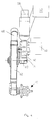
- eine Baugruppe der Einrichtung, dargestellt als vergrößerter Ausschnitt aus Fig.2,
- Fig.4
- die Ansicht in Richtung des Pfeils IV in Fig.3,
- Fig.5
- die Draufsicht in Richtung des Pfeils V in Fig.3 und
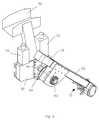
- Fig.6
- eine Schrägansicht der genannten Baugruppe.
Claims (10)
- Einrichtung zum Wechseln von Gegenständen wie Werkstücke (W) oder Werkzeuge zwischen einem Arbeitsraum (30) einer Werkzeugmaschine (10), insbesondere Drehmaschine, und einem Magazin (44), mit >einer Längsführung (40), die über der Werkzeugmaschine (10), insbesondere parallel zu einer zu bedienenden Arbeitsspindel (16), angeordnet ist,einem Wagen (50), der mit einem Fahrantrieb (56) entlang der Längsführung (40) zwischen dem Magazin (44) und der Werkzeugmaschine (10) verfahrbar ist,einem Träger (62), der in bezug auf den Wagen (50) um eine zur Längsführung (40) normale waagerechte Schwenkachse (A) schwenkbar ist und eine Greiferanordnung (70) trägt,einem Hubantrieb (58) zum Absenken und Anheben des Trägers (62) zwischen einer oberen Stellung, in welcher der Wagen (50) mit der Greiferanordnung (70) über die Werkzeugmaschine (10) hinwegbewegbar ist, und einer unteren Stellung, in welcher der Träger (62) mit der Greiferanordnung (70) in den Arbeitsraum (30) eintaucht, undeiner die Antriebe (56, 58) koordinierenden Steuereinrichtung, dadurch gekennzeichnet, daßdie Greiferanordnung (70) an einem Ende des Trägers (62) gelagert ist,der Träger (62) am Wagen (50) derart pendelnd gelagert ist, daß sein Schwenkbereich sich erstreckt mindestens zwischen einer nur wenig geneigten Stellung, in der das genannte Ende vorne und oben ist, und einer steil nach unten weisenden Stellung, in der das genannte Ende unten ist,die Werkzeugmaschine (10) oberhalb des Arbeitsraumes (30) einen turmartigen Gehäuseaufsatz (34) aufweist, der an seiner dem Magazin (44) zugewandten Seite eine Klappe (36) aufweist, undder Hubantrieb (58) für eine mit der Bewegung des Wagens (50) entlang der Längsführung (40) koordinierte, mit ihr mindestens teilweise gleichzeitige Schwenkung des Trägers (62) steuerbar ist, so daßder Träger (62) bei geöffneter Klappe (36) schräg von oben her und dann allmählich eine steilere Stellung einnehmend in den Arbeitsraum (30) eintaucht.
- Einrichtung nach Anspruch 1,
dadurch gekennzeichnet, daß der Träger (62) so gesteuert ist, daß er jeweils zu Beginn des Eintauchens in den Arbeitsraum (30) schräg vorwärts und abwärts gerichtet ist. - Einrichtung nach Anspruch 2,
dadurch gekennzeichnet, daß der Träger (62) zwischen der Werkzeugmaschine (10) und dem Magazin (44) über eine senkrechte Stellung hinaus in Richtung von der Werkzeugmaschine (10) weg schwenkbar ist. - Einrichtung nach Anspruch 3,
dadurch gekennzeichnet, daß der Träger (62) in bezug auf eine Mittellage, in der er senkrecht nach unten gerichtet ist, nach vorne und hinten um je 70° bis 80° schwenkbar ist. - Einrichtung nach einem der Ansprüche 1 bis 4,
dadurch gekennzeichnet, daß die Längsführung (40) vor dem Gehäuseaufsatz (34) endet. - Einrichtung nach einem der Ansprüche 1 bis 5,
dadurch gekennzeichnet, daß die Klappe (36) in das Innere des Gehäuseaufsatzes (34) hinein zu öffnen ist. - Einrichtung nach einem der Ansprüche 1 bis 6,
dadurch gekennzeichnet, daß die Klappe (36) durch die Bewegung des Wagens (50) so gesteuert ist, daß sie sich jeweils unmittelbar vor der Ankunft des Trägers (62) am Gehäuseaufsatz (34) öffnet und nach dem Rückzug des Trägers schließt. - Einrichtung nach einem der Ansprüche 1 bis 7,
dadurch gekennzeichnet, daß die Klappe (36) in geschlossener Stellung von der Oberseite eines Spindelstocks (14), oberhalb dessen die Längsführung (40) angeordnet ist, und in dem die Arbeitsspindel (16) gelagert ist, schräg in Richtung vom Magazin (44) weg über dem Arbeitsraum (30) ansteigend geneigt ist. - Einrichtung nach einem der Ansprüche 1 bis 8,
dadurch gekennzeichnet, daß die Schwenkachse (A) des Trägers (62) von einem unterhalb der Längsführung (40) am Wagen (50) angeordneten Schwenklager (60) gebildet ist. - Einrichtung nach einem der Ansprüche 1 bis 9,
dadurch gekennzeichnet. daß die Greiferanordnung (70) zwei Greifer (74, 76) aufweist, die gemeinsam um eine zur Schwenkachse (A) des Trägers (62) parallele Achse (B) schwenkbar sind.
Applications Claiming Priority (2)
| Application Number | Priority Date | Filing Date | Title |
|---|---|---|---|
| DE19515041 | 1995-04-24 | ||
| DE19515041A DE19515041C1 (de) | 1995-04-24 | 1995-04-24 | Einrichtung zum Wechseln von Gegenständen zwischen einer Werkzeugmaschine und einem Magazin |
Publications (2)
| Publication Number | Publication Date |
|---|---|
| EP0739681A1 EP0739681A1 (de) | 1996-10-30 |
| EP0739681B1 true EP0739681B1 (de) | 1998-06-24 |
Family
ID=7760241
Family Applications (1)
| Application Number | Title | Priority Date | Filing Date |
|---|---|---|---|
| EP96106107A Expired - Lifetime EP0739681B1 (de) | 1995-04-24 | 1996-04-18 | Einrichtung zum Wechseln von Gegenständen zwischen einer Werkzeugmaschine und einem Magazin |
Country Status (2)
| Country | Link |
|---|---|
| EP (1) | EP0739681B1 (de) |
| DE (2) | DE19515041C1 (de) |
Families Citing this family (7)
| Publication number | Priority date | Publication date | Assignee | Title |
|---|---|---|---|---|
| DE19815858A1 (de) * | 1998-04-08 | 1999-10-21 | Juergen Roeders | Werkzeugmaschine mit Werkstückwechseleinrichtung |
| DE102006003985A1 (de) * | 2006-01-20 | 2007-07-26 | Index-Werke Gmbh & Co. Kg Hahn & Tessky | Werkzeugmaschine |
| DE102007040491A1 (de) * | 2007-08-28 | 2009-03-05 | Ads-Tec Gmbh | Werkstückwechselsystem |
| US20130040792A1 (en) * | 2010-02-18 | 2013-02-14 | Gmtk Multi-Process Machining, S.A. | Equipment for the exchange of replaceable components in machine tools |
| CN107598191A (zh) * | 2017-10-31 | 2018-01-19 | 东北大学 | 一种数控车床自动送料装置 |
| CN109866168B (zh) * | 2019-04-03 | 2024-04-12 | 江苏金龙科技股份有限公司 | 刺花机针板装卸用的小车结构 |
| CN114670049B (zh) * | 2022-04-14 | 2023-12-08 | 广西凯硕智能科技有限公司 | 一种数控自动化板材加工自动送料装置及方法 |
Family Cites Families (5)
| Publication number | Priority date | Publication date | Assignee | Title |
|---|---|---|---|---|
| US2714324A (en) * | 1952-07-24 | 1955-08-02 | Seneca Falls Machine Co | Work-handling mechanism for a machine tool |
| DE1094070B (de) * | 1953-03-17 | 1960-12-01 | Seneca Falls Machine Co | Werkstueckwechselvorrichtung fuer Werkzeugmaschinen |
| GB2126135B (en) * | 1982-09-03 | 1986-01-08 | 600 Group P L C The | A robot serviced machine tool |
| DE3409682A1 (de) * | 1984-03-16 | 1985-09-19 | Heyligenstaedt & Co, Werkzeugmaschinenfabrik Gmbh, 6300 Giessen | Verfahren zum betreiben einer drehmaschine sowie vorrichtung zu seiner durchfuehrung |
| DE3420531C2 (de) * | 1984-06-01 | 1986-07-03 | Index-Werke Kg Hahn & Tessky, 7300 Esslingen | Drehautomat |
-
1995
- 1995-04-24 DE DE19515041A patent/DE19515041C1/de not_active Expired - Fee Related
-
1996
- 1996-04-18 DE DE59600296T patent/DE59600296D1/de not_active Expired - Fee Related
- 1996-04-18 EP EP96106107A patent/EP0739681B1/de not_active Expired - Lifetime
Also Published As
| Publication number | Publication date |
|---|---|
| EP0739681A1 (de) | 1996-10-30 |
| DE19515041C1 (de) | 1996-08-29 |
| DE59600296D1 (de) | 1998-07-30 |
Similar Documents
| Publication | Publication Date | Title |
|---|---|---|
| EP1982799B1 (de) | Handhabungsanordnung | |
| EP1418019B1 (de) | Werkzeugmaschine mit mindestens zwei Werkzeugrevolvern, die jeweils eine Werkstückgreifvorrichtung aufweisen | |
| EP1016497B1 (de) | Werkzeugmaschine | |
| DE1477358A1 (de) | Werkzeugmaschine mit automatischer Werkzeugwechselvorrichtung | |
| EP1733840A1 (de) | Bearbeitungsmaschinenanordnung mit Roboter und Werkzeugmagazin | |
| EP0654318A1 (de) | Maschine zum Feinbearbeiten der Zahnflanken von zahnradförmigen Werkstücken mit einem innenverzahnten Werkzeug | |
| EP0369232A2 (de) | Werkzeugmaschine | |
| DE2904088C2 (de) | Be- und/oder Entladeeinrichtung für Werkzeugmaschinen, insbesondere Drehautomaten | |
| DE3017613C2 (de) | ||
| DE3440604A1 (de) | Automatische werkzeugwechseleinrichtung fuer werkzeugmaschinen, insbesondere fuer universalbearbeitungszentren | |
| EP0310128A2 (de) | Werkzeugwechselsystem | |
| DE19500652C1 (de) | Handhabungsvorrichtung für eine Werkzeugmaschine | |
| DE19938442A1 (de) | Automatische Werkzeugwechselvorrichtung für Werkzeugmaschinen | |
| EP0480191B1 (de) | Vorrichtung zum Bearbeiten von Stangen | |
| DE19934598B4 (de) | Universal-Fräs- und Bohrmaschine | |
| DE19515041C1 (de) | Einrichtung zum Wechseln von Gegenständen zwischen einer Werkzeugmaschine und einem Magazin | |
| EP0157950B1 (de) | Werkzeugmaschine mit einem in mehreren Achsen beweglichen Spindelstock | |
| EP0331178A1 (de) | Kompaktaufbau einer Säulenbohrmaschine | |
| DE19547033C2 (de) | Verfahrbare Brennschneidmaschine mit einem Höheneinsteller an einem Querwagen | |
| DE1138607B (de) | Einrichtung zum selbsttaetigen Werkstueckwechsel an Waelzfraesmaschinen | |
| EP0949029B1 (de) | Maschine zur Bearbeitung von stangenförmigen Werkstücken | |
| EP1084794A1 (de) | Ladevorrichtung zum Beladen von Maschinen mit Teilen, wie Werkstücken, Paletten, Futterteilen, Werkzeugen od.dgl. | |
| EP1074338B1 (de) | Werkzeugmaschinenführungssystem bzw. Mehrachsenroboter für eine Mehrzahl von Werkzeugen | |
| EP0881031A1 (de) | Werkzeugmaschine, insbesondere ein CNC-gesteuertes Bearbeitungszentrum, mit einer automatischen Werkzeugwechseleinrichtung | |
| DE3902341A1 (de) | Greifer eines industrieroboters |
Legal Events
| Date | Code | Title | Description |
|---|---|---|---|
| PUAI | Public reference made under article 153(3) epc to a published international application that has entered the european phase |
Free format text: ORIGINAL CODE: 0009012 |
|
| AK | Designated contracting states |
Kind code of ref document: A1 Designated state(s): DE GB IT |
|
| 17P | Request for examination filed |
Effective date: 19961002 |
|
| GRAG | Despatch of communication of intention to grant |
Free format text: ORIGINAL CODE: EPIDOS AGRA |
|
| 17Q | First examination report despatched |
Effective date: 19970326 |
|
| GRAG | Despatch of communication of intention to grant |
Free format text: ORIGINAL CODE: EPIDOS AGRA |
|
| GRAG | Despatch of communication of intention to grant |
Free format text: ORIGINAL CODE: EPIDOS AGRA |
|
| GRAH | Despatch of communication of intention to grant a patent |
Free format text: ORIGINAL CODE: EPIDOS IGRA |
|
| GRAH | Despatch of communication of intention to grant a patent |
Free format text: ORIGINAL CODE: EPIDOS IGRA |
|
| GRAA | (expected) grant |
Free format text: ORIGINAL CODE: 0009210 |
|
| RAP1 | Party data changed (applicant data changed or rights of an application transferred) |
Owner name: TRAUB DREHMASCHINEN GMBH |
|
| AK | Designated contracting states |
Kind code of ref document: B1 Designated state(s): DE GB IT |
|
| PG25 | Lapsed in a contracting state [announced via postgrant information from national office to epo] |
Ref country code: IT Free format text: LAPSE BECAUSE OF FAILURE TO SUBMIT A TRANSLATION OF THE DESCRIPTION OR TO PAY THE FEE WITHIN THE PRE;WARNING: LAPSES OF ITALIAN PATENTS WITH EFFECTIVE DATE BEFORE 2007 MAY HAVE OCCURRED AT ANY TIME BEFORE 2007. THE CORRECT EFFECTIVE DATE MAY BE DIFFERENT FROM THE ONE RECORDED.SCRIBED TIME-LIMIT Effective date: 19980624 |
|
| GBT | Gb: translation of ep patent filed (gb section 77(6)(a)/1977) |
Effective date: 19980624 |
|
| REF | Corresponds to: |
Ref document number: 59600296 Country of ref document: DE Date of ref document: 19980730 |
|
| PLBE | No opposition filed within time limit |
Free format text: ORIGINAL CODE: 0009261 |
|
| STAA | Information on the status of an ep patent application or granted ep patent |
Free format text: STATUS: NO OPPOSITION FILED WITHIN TIME LIMIT |
|
| 26N | No opposition filed | ||
| REG | Reference to a national code |
Ref country code: GB Ref legal event code: IF02 |
|
| PGFP | Annual fee paid to national office [announced via postgrant information from national office to epo] |
Ref country code: GB Payment date: 20040317 Year of fee payment: 9 |
|
| PGFP | Annual fee paid to national office [announced via postgrant information from national office to epo] |
Ref country code: DE Payment date: 20040426 Year of fee payment: 9 |
|
| PG25 | Lapsed in a contracting state [announced via postgrant information from national office to epo] |
Ref country code: GB Free format text: LAPSE BECAUSE OF NON-PAYMENT OF DUE FEES Effective date: 20050418 |
|
| PG25 | Lapsed in a contracting state [announced via postgrant information from national office to epo] |
Ref country code: DE Free format text: LAPSE BECAUSE OF NON-PAYMENT OF DUE FEES Effective date: 20051101 |
|
| GBPC | Gb: european patent ceased through non-payment of renewal fee |
Effective date: 20050418 |