EP0739642A2 - Herzleitung mit isolierender Verbundstruktur - Google Patents
Herzleitung mit isolierender Verbundstruktur Download PDFInfo
- Publication number
- EP0739642A2 EP0739642A2 EP96250078A EP96250078A EP0739642A2 EP 0739642 A2 EP0739642 A2 EP 0739642A2 EP 96250078 A EP96250078 A EP 96250078A EP 96250078 A EP96250078 A EP 96250078A EP 0739642 A2 EP0739642 A2 EP 0739642A2
- Authority
- EP
- European Patent Office
- Prior art keywords
- insulation
- lead
- electrode
- silicone
- polyurethane
- Prior art date
- Legal status (The legal status is an assumption and is not a legal conclusion. Google has not performed a legal analysis and makes no representation as to the accuracy of the status listed.)
- Granted
Links
Images

Classifications
-
- A—HUMAN NECESSITIES
- A61—MEDICAL OR VETERINARY SCIENCE; HYGIENE
- A61N—ELECTROTHERAPY; MAGNETOTHERAPY; RADIATION THERAPY; ULTRASOUND THERAPY
- A61N1/00—Electrotherapy; Circuits therefor
- A61N1/02—Details
- A61N1/04—Electrodes
- A61N1/05—Electrodes for implantation or insertion into the body, e.g. heart electrode
- A61N1/056—Transvascular endocardial electrode systems
- A61N1/0563—Transvascular endocardial electrode systems specially adapted for defibrillation or cardioversion
-
- A—HUMAN NECESSITIES
- A61—MEDICAL OR VETERINARY SCIENCE; HYGIENE
- A61N—ELECTROTHERAPY; MAGNETOTHERAPY; RADIATION THERAPY; ULTRASOUND THERAPY
- A61N1/00—Electrotherapy; Circuits therefor
- A61N1/02—Details
- A61N1/04—Electrodes
- A61N1/05—Electrodes for implantation or insertion into the body, e.g. heart electrode
- A61N1/056—Transvascular endocardial electrode systems
Definitions
- the present invention generally relates to a lead for implantation in a human body and for use with an implantable cardiac device, such as a pacemaker or cardiovertor/ defibrillator.
- the present invention is more particularly directed to such a lead having a composite insulating structure formed from two different insulating materials, one overlying the other, which results in a lead having superior overall characteristics including, for example, improved mechanical properties, improved resistance to biodegradation, and improved blood surface compatibility.
- Implantable leads for implantable cardiac devices are well known.
- a lead generally includes one or more electrodes for making electrical contact with a patient's heart, a connector for connecting the lead to the implantable device, and one or more conductors for coupling the electrode or electrodes to the connector.
- the lead also includes an outer insulation for electrically insulating the conductor or conductors so that only the electrodes may make electrical contact with the patient's body tissue. Ideally, the outer insulation for this intended use should possess a number preferred characteristics.
- One such characteristic relates to flexibility.
- the more flexible a lead is the less trauma is induced to the patient's tissues by implanted lead pressure.
- the flexibility of lead insulation is an important factor in the overall flexibility of a lead. Hence, it is highly desirable for the lead insulation to be flexible.
- insulators Another preferred characteristic of such insulators relates to their mechanical properties. It is preferable that such insulators have good tensile properties so that, in spite of unavoidable manipulation of a lead during implant, the structural integrity of the lead is maintained. It is further preferable that the outer insulation material have resistance to abrasive wear in the event that the lead rubs against another lead, another implanted device, or anatomical structure while in use after implantation.
- Biostability is another characteristic important to implantable leads, and more particularly to the insulation material used as the lead outer insulation. Biostability relates to the ability of a lead insulation material to resist degradation in the implant ( in vivo ) environment.
- ESC environmental stress cracking
- MIO metal ion induced oxidation
- ESC is characterized by surface cracks in the insulation, believed to be produced by a combined interaction of the environment (internal body fluids) acting on the insulation, and stress on the insulation material.
- MIO is an accelerated degradation from reaction with metal ions, such as cobalt ions, chromium ions or the like, used alone or in alloy form in lead conductors.
- Still another preferred characteristic of an insulation for implantable lead use is blood surface compatibility. This relates to the degree in which the surface provided by the insulation material contributes to the formation of blood clots around the lead.
- An insulation which presents a highly blood compatible surface is one which contributes little to blood clot formation.
- an insulator which provides a highly blood compatible surface is desirable for implantable lead applications.
- Leads which incorporate insulators having a low coefficient of friction in blood are easier to implant because such leads more readily slide against each other and into veins and arteries.
- a low coefficient of friction in blood is a preferred characteristic for insulators used in forming implantable cardiac leads.
- the two most common polymeric materials used for outer insulation in implantable leads today are silicone and polyurethane. Each type of material exhibits its own unique set of positive and negative properties for use in implantable cardiac leads.
- Silicone exhibits superior flexibility. It also is highly biostable, being essentially impervious to ESC and MIO.
- Silicone does exhibit some disadvantages. For example, silicone has rather inferior mechanical properties. More particularly, it has rather poor tensile and wear characteristics. In addition, silicone does not provide a surface which is as compatible in blood as some other materials. It also has a rather high coefficient of friction in blood.
- Polyurethane for use as an insulation in implantable cardiac leads, has its own set of advantages. It has good mechanical properties in terms of tensile, toughness and wear characteristics. The mechanical properties of polyurethane are so good that leads using polyurethane as an outer insulation can be made to have thin insulator wall constructions, permitting small lead outer diameter dimensions to be obtained. It also provides a highly blood-compatible surface which can minimize clotting. It also has a very low coefficient of friction in blood, rendering polyurethane outer insulation leads much easier to slide into an artery or vein during implantation than, for example, outer insulation silicone leads.
- Polyurethane is not without its disadvantages for implantable lead use. It generally is not as biostable as other materials, such as silicone. Some forms of polyurethane are reportedly especially susceptible to MIO and ESC. Polyurethane, in general, and some forms of polyurethane specifically, are considered to be stiffer than desirable for implantation use.
- the prior art implantable leads using either silicone alone or polyurethane materials alone for outer insulation, have both positive characteristics and unavoidable negative characteristics.
- Leads incorporating silicone insulation are comparatively biostable because silicone is resistant to ESC and MIO.
- they have inferior mechanical properties (tensile, toughness and wear) and provide a surface having neither high blood surface compatibility nor a low coefficient of friction in blood.
- Leads incorporating polyurethane insulation have good mechanical properties (tensile, toughness, wear). Further, such leads provide a highly blood-compatible and low coefficient of friction surface.
- polyurethane is not highly biostable and is generally, comparatively stiff. A lead incorporating either material alone is therefore a compromise.
- the present invention provides a lead for implantation in the human body which overcomes the above-noted disadvantages in the prior art. More particularly, the lead of the present invention provides a composite insulating structure, formed of at least two different materials, resulting in lead performance which capitalizes on all of the advantages of the insulating materials utilized while, at the same time, negating the disadvantages of each of the insulating materials.
- the invention therefore provides a lead for implantation in a human body.
- the lead includes a lead body and electrode means carried by the lead body for establishing electrical contact with the human body.
- the lead body includes a conductor contacting the electrode means, a first insulation surrounding and immediately adjacent to the conductor, and a second insulation surrounding and immediately adjacent to the first insulation.
- the first insulation and second insulation are formed of different insulating materials.
- the first insulation is formed of silicone and the second insulation is formed of polyurethane.
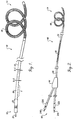
- Figure 1 is a side plan view of a first implantable cardiac lead embodying the present invention, the lead including a single electrode at the distal end thereof.
- Figure 2 is a side plan view of a second implantable cardiac lead embodying the present invention, the second lead including a pair of electrodes.
- Figure 3 is a side plan view of a third implantable cardiac lead embodying the present invention, the third lead being particularly adapted for implantation in a chamber of the heart.
- Figure 4 is a partial side plan view, with a portion broken away, and to an enlarged scale to illustrate the composite outer insulating structure of the leads of Figures 1-3, in accordance with the present invention.
- Figure 5 is a cross-sectional view, to an enlarged scale, taken along lines 5-5 of Figure 1.
- FIG. 1 it illustrates a first lead 10 embodying the present invention.
- the lead 10 and the second and third leads 40 and 50, illustrated in Figures 2 and 3 respectively, are all implantable cardiac leads and primarily adapted for use with an implantable atrial defibrillator/cardiovertor, as described, for example, in U.S. Patent No. 5,350,404, issued on September 27, 1994, for LEAD SYSTEM FOR USE WITH AN ATRIAL DEFIBRILLATOR AND METHOD, which is assigned to the assignee of the present invention and incorporated herein by reference.
- the present invention is equally as applicable to any type of implantable lead for use with any type of implantable cardiac device, such as pacemakers or ventricular defibrillators/ cardiovertors, for example.
- the lead 10 of Figure 1 includes a lead body 12 having a distal end 14 and a proximal end 16.
- An elongated electrode 18 is carried on the lead body 12 at the distal end 14.
- a conductor 20 (Figure 5), in the form of a stylet coil, is connected to the electrode 18 and couples the electrode 18 to a pin 24 of a connector 22, carried at the proximal end 16 of the lead 10.
- the connector 22 serves to couple the lead 10, and more specifically the electrode 18, to internal circuitry of an implantable cardiac device, such as an implantable atrial defibrillator/cardiovertor as contemplated herein.
- a section 4 of the lead body 12 is more particularly illustrated in Figure 4.
- the outer insulation 26 includes a first insulation 28 and a second insulation 30.
- the first insulation 28 encircles or surrounds the conductor 20
- the second insulation 30 encircles or surrounds the first insulation 28.
- the first insulation 28 is immediately adjacent to the conductor 20, and the second insulation 30 is immediately adjacent the first insulation 28.
- the first and second insulations are co-extensive, forming a composite outer insulation structure, extending from the electrode 18 to the connector 22.
- FIG 2 it illustrates a second lead 40 embodying the present invention.
- the second lead 40 is similar to the lead 10 of Figure 1, except that it includes a second electrode 42.
- the lead 40 includes a lead body 44 having a distal end 14 and a proximal end 16.
- An elongated electrode 18 is carried on the lead body 44 at the distal end 14.
- the conductor 20 ( Figure 5) connects the electrode 18 to a pin 24a of a connector 22a carried at the proximal end 16 of the lead 40.
- the second electrode 42 is carried by the lead body 44 intermediate the electrode 18 and the connector 22.
- a second conductor may be coaxially disposed in relation to the conductor 20 for coupling the electrode 42 to a second pin 24b of a second connector 22b.
- the connectors 22a and 22b are provided separate from each other so that each may be independently coupled to its own corresponding connector socket of an implantable cardiac device, such as an implantable atrial defibrillator/ cardiovertor as contemplated herein.
- the outer insulation 26 extends from a bifurcation 44 to the second electrode 42, and from the second electrode 42 to the first electrode 18.
- the outer insulation 26 preferably takes the form, as illustrated in Figures 4 and 5, to include the first insulation 28 and the second insulation 30.
- the first and second insulations 28 and 30 be co-extensive between the bifurcation 44 and the electrode 42, and between the electrode 42 and the electrode 18.
- the second insulation 30 may be segmented to cover selected portions of the lead 40 to serve as one or more protective sleeves. In doing so, the first insulation 28 would be relied upon for providing electrical insulation and biostability.
- the protective sleeves may be relied upon for their mechanical properties, such as abrasive wear resistance.
- the lead 10 of Figure 1 and the lead 40 of Figure 2, as described in the aforementioned U.S. Patent No. 5,350,404, are particularly adapted for implantation in the coronary sinus and great cardiac vein of the heart to dispose the electrode 18 in the coronary sinus and great cardiac vein adjacent the left atrium.
- a preferred path for implanting the leads 10 and 40 extends down the superior vena cava, into the right atrium, through the ostium of the coronary sinus, into the coronary sinus, and to the great cardiac vein to place the electrode 18 in the coronary sinus and great cardiac vein of the heart.
- the electrodes 18 and 42 are preferably displaced on the lead body 44 such that when the electrode 18 is in the coronary sinus and great cardiac vein, the electrode 42 resides in the right atrium.
- the lead 50 illustrated in Figure 3 and to which reference is now directed, is particularly adapted for implantation in the right atrium of the heart for use in atrial cardioversion/defibrillation in conjunction with the first lead 10 of Figure 1.
- the lead 50 includes a lead body 52 having a distal end 54 and a proximal end 56.
- An elongated electrode 58 is carried on the lead body 52 at the distal end 54.
- a conductor such as the conductor 20 ( Figure 5), couples the electrode 58 to a pin 64 of a connector 62 at the proximal end 56 of the lead body 52.
- the lead 50 may be implanted by being fed down the superior vena cava to the right atrium. This places the electrode 58 in the right atrium.
- the distal end 54 includes a helical projection 60 for anchoring the distal end 54 of the lead in a manner known in the art.
- the lead body 52 includes a composite outer insulation 26 extending proximally from the electrode 58, and preferably having the construction shown in Figures 4 and 5.
- the first insulation 28 extends from the electrode 58 to the connector 62 while the second insulation 30 extends proximally from the electrode 58 and terminates at a point intermediate the electrode 58 and the connector 62.
- the second insulation 30 may be configured to extend co-extensively with the first insulation 28 so as to also extend from the electrode 58 to the connector 62.
- the first insulation 28 and the second insulation 30 are formed of different insulating materials, not including different compositional variations of the same type material as described, for example, in U.S. Patent No. 5,375,609.
- the first insulation is preferably formed from silicone, such as Silicone Q7-4765, manufactured by Dow Corning Co. of Midland, MI, or MED-4765, manufactured by NuSil Technology of Carpenteria, CA
- the second insulation is preferably formed from polyurethane having a durometer of, for example, 55D, such as Pellethane 2363-55D, manufactured by Dow Chemical Co. of Midland, MI.
- silicone is meant to relate to any of the versions of silicone rubber polymers suitable for implantation.
- polyurethane is meant to relate to any of the versions or family types of polymers, known generically as polyurethanes, which are suitable for implantation.
- the silicone first insulation preferably has an outer diameter of 0.061 inch and a wall thickness of 0.012 inch.
- the polyurethane second insulation preferably has an outer diameter of 0.079 inch, and a wall thickness of 0.006 inch.
- the polyurethane insulation tubing may be disposed over the silicone insulation tubing by first coating the outer surface of the silicone tubing with isopropyl alcohol to reduce the friction of the silicone to polyurethane, and then quickly sliding the polyurethane tubing over the silicone.
- Silicone is more biostable than polyurethane.
- the silicone first insulation 28 will provide both biostability and electrical insulation for the leads.
- the leads 10, 40 and 50 capitalize on the biostability characteristics of the silicone insulation.
- the rather inferior biodegradation characteristics of the polyurethane insulation 30 are minimized or negated because the silicone insulation 28 protects the polyurethane insulation 30 from the biodegradation effects of failure mechanisms, such as MIO.
- the leads 10, 40 and 50 will have a flexibility which is only slightly less than the flexibility of silicone alone, and which is much greater than the flexibility of commonly used polyurethanes alone at comparable thicknesses.
- the leads 10, 40 and 50 capitalize on the flexibility of the silicone insulation which, at the same time, negates the inflexibility of the polyurethane insulation.
- the polyurethane second insulation 30 will present a highly compatible surface to the blood.
- the leads 10, 40 and 50 will capitalize on the blood surface compatibility characteristics of the polyurethane insulation, while negating the rather poor blood surface compatibility characteristics of the silicone insulation.
- the polyurethane second insulation 30 capitalizes on its greatly lower coefficient of friction in blood and negates the much higher coefficient of friction in blood of silicone.
- the coefficient in blood of silicone is nearly twenty times the coefficient in blood of polyurethane.
- the present invention results in a lead which slides much more readily in an artery or vein, or against other leads, during implantation, as compared to a lead having silicone insulation alone.
- the resulting leads 10, 40 and 50 also capitalize upon the durability of the polyurethane insulation in terms of tensile, toughness and wear characteristics. Because the polyurethane is the outermost insulation, these characteristics are capitalized upon while the rather poor characteristics of silicone, in terms of tensile, toughness and wear characteristics, are negated.
- polyurethanes of softer durometer may be utilized to advantage as the second insulation 30 in accordance with the present invention.
- Polyurethanes having a durometer of, for example, 80A which are softer than polyurethanes having a durometer of, for example, 55D, may be utilized in the second insulation 30.
- polyurethanes of softer durometer generally are more susceptible to ESC and MIO, by being the most outer insulation layer, these insulations will be protected from MIO by the inner silicone insulation. Even if the outer insulation 30 should develop cracks due, for example, to ESC, the lead will still retain its superior mechanical characteristics while the first insulation 28 continues to provide biostability and electrical isolation.
- implantable lead constructions having improved combined characteristics, including flexibility, resistance to wear, ease of implant, blood surface compatibility and biodegradation, are rendered possible by the present invention.
- the present invention applies equally as well to implantable leads having one or more lumens for coupling lead electrodes to lead connectors.
- the present invention applies equally as well to implantable leads having one or more lumens for coupling lead electrodes to lead connectors.
Landscapes
- Health & Medical Sciences (AREA)
- Heart & Thoracic Surgery (AREA)
- Cardiology (AREA)
- Nuclear Medicine, Radiotherapy & Molecular Imaging (AREA)
- Engineering & Computer Science (AREA)
- Biomedical Technology (AREA)
- Vascular Medicine (AREA)
- Radiology & Medical Imaging (AREA)
- Life Sciences & Earth Sciences (AREA)
- Animal Behavior & Ethology (AREA)
- General Health & Medical Sciences (AREA)
- Public Health (AREA)
- Veterinary Medicine (AREA)
- Electrotherapy Devices (AREA)
Applications Claiming Priority (2)
| Application Number | Priority Date | Filing Date | Title |
|---|---|---|---|
| US429886 | 1995-04-27 | ||
| US08/429,886 US5628774A (en) | 1995-04-27 | 1995-04-27 | Cardiac lead with composite insulating structure |
Publications (3)
| Publication Number | Publication Date |
|---|---|
| EP0739642A2 true EP0739642A2 (de) | 1996-10-30 |
| EP0739642A3 EP0739642A3 (de) | 1997-07-02 |
| EP0739642B1 EP0739642B1 (de) | 2006-11-22 |
Family
ID=23705123
Family Applications (1)
| Application Number | Title | Priority Date | Filing Date |
|---|---|---|---|
| EP96250078A Expired - Lifetime EP0739642B1 (de) | 1995-04-27 | 1996-04-09 | Herzleitung mit isolierender Verbundstruktur |
Country Status (5)
| Country | Link |
|---|---|
| US (1) | US5628774A (de) |
| EP (1) | EP0739642B1 (de) |
| AU (1) | AU694332B2 (de) |
| CA (1) | CA2173311C (de) |
| DE (1) | DE69636709T2 (de) |
Cited By (10)
| Publication number | Priority date | Publication date | Assignee | Title |
|---|---|---|---|---|
| WO1998034678A1 (en) * | 1997-02-10 | 1998-08-13 | Medtronic, Inc. | Coiled wire conductor insulation for biomedical lead |
| WO1999003530A1 (en) * | 1997-07-17 | 1999-01-28 | Medtronic, Inc. | Medical electrical lead |
| US7146227B2 (en) | 2000-10-04 | 2006-12-05 | Cochlear Limited | Combination stylet and straightening coating for a cochlear implant electrode array |
| US7269461B2 (en) | 2000-10-11 | 2007-09-11 | Cochlear Limited | Double stylet insertion tool for a cochlear implant electrode array |
| US7272449B2 (en) | 2000-10-04 | 2007-09-18 | Cochlear Limited | Cochlear implant electrode array |
| US7894916B2 (en) | 2000-10-17 | 2011-02-22 | Cochlear Limited | Insertion tool for a cochlear implant electrode array |
| US8133215B2 (en) | 2007-08-13 | 2012-03-13 | Cochlear Limited | Independently-manufactured drug delivery module and corresponding receptacle in an implantable medical device |
| US8401674B2 (en) | 2000-11-14 | 2013-03-19 | Cochlear Limited | Apparatus for delivery of pharmaceuticals to the cochlea |
| US8617097B2 (en) | 2010-05-24 | 2013-12-31 | Cochlear Limited | Drug-delivery accessory for an implantable medical device |
| US9089450B2 (en) | 2000-11-14 | 2015-07-28 | Cochlear Limited | Implantatable component having an accessible lumen and a drug release capsule for introduction into same |
Families Citing this family (19)
| Publication number | Priority date | Publication date | Assignee | Title |
|---|---|---|---|---|
| US6477428B1 (en) | 2000-02-28 | 2002-11-05 | Cardiac Pacemakers, Inc. | Endocardial lead with vinylidene fluoride insulation |
| US6701191B2 (en) * | 2001-05-30 | 2004-03-02 | Cardiac Pacemakers, Inc. | Lead having composite tubing |
| US7257449B2 (en) * | 2001-05-30 | 2007-08-14 | Cardiac Pacemakers, Inc. | Extendable/retractable lead having downsized lead body |
| US6606522B2 (en) | 2001-05-30 | 2003-08-12 | Cardiac Pacemakers, Inc. | Torque mechanism and method for endocardial leads |
| US7904178B2 (en) * | 2002-04-11 | 2011-03-08 | Medtronic, Inc. | Medical electrical lead body designs incorporating energy dissipating shunt |
| US8396568B2 (en) * | 2002-04-11 | 2013-03-12 | Medtronic, Inc. | Medical electrical lead body designs incorporating energy dissipating shunt |
| US20030199952A1 (en) * | 2002-04-22 | 2003-10-23 | Stolz Brian T. | Implantable lead with improved distal tip |
| US8000802B2 (en) | 2002-04-22 | 2011-08-16 | Medtronic, Inc. | Implantable lead with coplanar contact coupling |
| US7184840B2 (en) * | 2002-04-22 | 2007-02-27 | Medtronic, Inc. | Implantable lead with isolated contact coupling |
| US6990378B1 (en) | 2003-09-30 | 2006-01-24 | Pacesetter, Inc. | Abrasion-resistant implantable medical lead and a method of fabricating such a lead |
| US7353066B1 (en) * | 2005-08-17 | 2008-04-01 | Pacesetter, Inc. | Self-sealing insulation employed on a catheter or lead |
| US20090171415A1 (en) * | 2006-04-27 | 2009-07-02 | Kenneth Dowling | Coated medical leads and method for preparation thereof |
| WO2008018820A1 (en) * | 2006-08-10 | 2008-02-14 | St. Jude Medical Ab | Passivated metal conductors for use in cardiac leads and method of prepararing the same |
| US20080183261A1 (en) * | 2007-01-31 | 2008-07-31 | Cardiac Pacemakers, Inc. | Fibrosis-limiting material attachment |
| JP2012506757A (ja) * | 2008-11-14 | 2012-03-22 | カーディアック ペースメイカーズ, インコーポレイテッド | 医療用電気リードおよびその製造方法 |
| US8478423B2 (en) * | 2009-04-07 | 2013-07-02 | Boston Scientific Neuromodulation Corporation | Insulator layers for leads of implantable electric stimulation systems and methods of making and using |
| US9192754B2 (en) | 2011-01-27 | 2015-11-24 | Carefusion 303, Inc. | Low permeability silicone rubber tubing |
| CN107510886A (zh) * | 2017-09-26 | 2017-12-26 | 杭州承诺医疗科技有限公司 | 一种骶神经刺激电极及其制作方法 |
| CN118249105A (zh) * | 2022-12-22 | 2024-06-25 | 武汉联影医疗科技有限公司 | 绝缘插头、高压线缆、x射线管以及x射线发生系统 |
Family Cites Families (8)
| Publication number | Priority date | Publication date | Assignee | Title |
|---|---|---|---|---|
| US4033355A (en) * | 1975-11-28 | 1977-07-05 | Cardiac Pacemakers, Inc. | Electrode lead assembly for implantable devices and method of preparing same |
| US4154247A (en) * | 1977-04-01 | 1979-05-15 | Medtronic, Inc. | Formable cardiac pacer lead and method of assembly and attachment to a body organ |
| US4851009A (en) * | 1985-12-16 | 1989-07-25 | Corvita Corporation | Crack prevention of implanted prostheses |
| US5433729A (en) * | 1991-04-12 | 1995-07-18 | Incontrol, Inc. | Atrial defibrillator, lead systems, and method |
| US5238007A (en) * | 1991-12-12 | 1993-08-24 | Vitatron Medical B.V. | Pacing lead with improved anchor mechanism |
| US5358516A (en) * | 1992-12-11 | 1994-10-25 | W. L. Gore & Associates, Inc. | Implantable electrophysiology lead and method of making |
| FR2696347A1 (fr) * | 1993-09-17 | 1994-04-08 | Gore & Ass | Conducteur implantable. |
| US5476501A (en) * | 1994-05-06 | 1995-12-19 | Medtronic, Inc. | Silicon insulated extendable/retractable screw-in pacing lead with high efficiency torque transfer |
-
1995
- 1995-04-27 US US08/429,886 patent/US5628774A/en not_active Expired - Lifetime
-
1996
- 1996-04-02 CA CA002173311A patent/CA2173311C/en not_active Expired - Fee Related
- 1996-04-09 DE DE69636709T patent/DE69636709T2/de not_active Expired - Lifetime
- 1996-04-09 EP EP96250078A patent/EP0739642B1/de not_active Expired - Lifetime
- 1996-04-09 AU AU50575/96A patent/AU694332B2/en not_active Ceased
Cited By (16)
| Publication number | Priority date | Publication date | Assignee | Title |
|---|---|---|---|---|
| WO1998034678A1 (en) * | 1997-02-10 | 1998-08-13 | Medtronic, Inc. | Coiled wire conductor insulation for biomedical lead |
| WO1999003530A1 (en) * | 1997-07-17 | 1999-01-28 | Medtronic, Inc. | Medical electrical lead |
| US7983767B2 (en) | 2000-10-04 | 2011-07-19 | Cochlear Limited | Cochlear implant electrode array |
| US7272449B2 (en) | 2000-10-04 | 2007-09-18 | Cochlear Limited | Cochlear implant electrode array |
| US7822487B2 (en) | 2000-10-04 | 2010-10-26 | Cochlear Limited | Combination stylet and sheath for an electrode array |
| US7146227B2 (en) | 2000-10-04 | 2006-12-05 | Cochlear Limited | Combination stylet and straightening coating for a cochlear implant electrode array |
| US8265773B2 (en) | 2000-10-04 | 2012-09-11 | Cochlear Limited | Electrode assembly having a flexible tip |
| US7974711B2 (en) | 2000-10-11 | 2011-07-05 | Cochlear Limited | Double stylet insertion tool for a cochlear implant electrode array |
| US7269461B2 (en) | 2000-10-11 | 2007-09-11 | Cochlear Limited | Double stylet insertion tool for a cochlear implant electrode array |
| US7894916B2 (en) | 2000-10-17 | 2011-02-22 | Cochlear Limited | Insertion tool for a cochlear implant electrode array |
| US9089450B2 (en) | 2000-11-14 | 2015-07-28 | Cochlear Limited | Implantatable component having an accessible lumen and a drug release capsule for introduction into same |
| US8401674B2 (en) | 2000-11-14 | 2013-03-19 | Cochlear Limited | Apparatus for delivery of pharmaceuticals to the cochlea |
| US9623221B2 (en) | 2000-11-14 | 2017-04-18 | Cochlear Limited | Apparatus for delivery of pharmaceuticals to the cochlea |
| US8133215B2 (en) | 2007-08-13 | 2012-03-13 | Cochlear Limited | Independently-manufactured drug delivery module and corresponding receptacle in an implantable medical device |
| US9101732B2 (en) | 2010-05-24 | 2015-08-11 | Cochlear Limited | Drug-delivery accessory for an implantable medical device |
| US8617097B2 (en) | 2010-05-24 | 2013-12-31 | Cochlear Limited | Drug-delivery accessory for an implantable medical device |
Also Published As
| Publication number | Publication date |
|---|---|
| DE69636709D1 (de) | 2007-01-04 |
| DE69636709T2 (de) | 2007-09-20 |
| AU694332B2 (en) | 1998-07-16 |
| CA2173311C (en) | 2001-10-02 |
| AU5057596A (en) | 1996-11-07 |
| EP0739642A3 (de) | 1997-07-02 |
| US5628774A (en) | 1997-05-13 |
| EP0739642B1 (de) | 2006-11-22 |
| CA2173311A1 (en) | 1996-10-28 |
Similar Documents
| Publication | Publication Date | Title |
|---|---|---|
| US5628774A (en) | Cardiac lead with composite insulating structure | |
| US5366496A (en) | Subcutaneous shunted coil electrode | |
| US5824030A (en) | Lead with inter-electrode spacing adjustment | |
| EP1592478B1 (de) | Medizinische elektrode mit lasttragender hülse | |
| US6434430B2 (en) | Co-extruded, multi-lumen medical lead | |
| US5374286A (en) | Torque indicator for fixed screw leads | |
| EP0428279B1 (de) | Geflochtene Elektrodenleitungen und Katheter für ihre Benutzung | |
| US7389148B1 (en) | Electrode design for defibrillation and/or sensing capabilities | |
| US6321123B1 (en) | J-shaped coronary sinus lead | |
| EP0606688B1 (de) | Vorrichtung zur Befestigung von Herzleitungen | |
| US5800497A (en) | Medical electrical lead with temporarily stiff portion | |
| US5476498A (en) | Coronary sinus channel lead and method | |
| US5919222A (en) | Adjustable medical electrode lead | |
| US5674272A (en) | Crush resistant implantable lead | |
| EP1017446B1 (de) | Medizinische elektrische leitung | |
| US7711437B1 (en) | Lead fixation device | |
| EP1324804B1 (de) | Biostabile kleine zuleitung | |
| JP4195290B2 (ja) | 収縮型スタイレット管腔を有するイントロデューサカテーテルのリード送り込み装置 | |
| EP0526671A1 (de) | Intravasale Defibrillationskathetereinheit mit getrennter bipolarer Abtastvorrichtung | |
| US6301507B1 (en) | Medical electrical lead having pre-formed atrial section | |
| US5843149A (en) | Electrical lead insulator | |
| US20020183824A1 (en) | Co-extruded, multi-lumen medical lead | |
| EP1224005B1 (de) | Steroidabgebende elektrodenanordnung für linksatriale medizinische leitungen | |
| EP1226843B1 (de) | Implantierbare Koronarsinusherzleitung mit einmaligem Durchgang zum Schrittmachen und Defibrillieren des Herzes und Verfahren zu deren Herstellung | |
| US6990378B1 (en) | Abrasion-resistant implantable medical lead and a method of fabricating such a lead |
Legal Events
| Date | Code | Title | Description |
|---|---|---|---|
| PUAI | Public reference made under article 153(3) epc to a published international application that has entered the european phase |
Free format text: ORIGINAL CODE: 0009012 |
|
| AK | Designated contracting states |
Kind code of ref document: A2 Designated state(s): BE CH DE FR IT LI NL SE |
|
| PUAL | Search report despatched |
Free format text: ORIGINAL CODE: 0009013 |
|
| AK | Designated contracting states |
Kind code of ref document: A3 Designated state(s): BE CH DE FR IT LI NL SE |
|
| 17P | Request for examination filed |
Effective date: 19970730 |
|
| RAP1 | Party data changed (applicant data changed or rights of an application transferred) |
Owner name: CARDIAC PACEMAKERS, INC. |
|
| 17Q | First examination report despatched |
Effective date: 20020116 |
|
| GRAP | Despatch of communication of intention to grant a patent |
Free format text: ORIGINAL CODE: EPIDOSNIGR1 |
|
| GRAS | Grant fee paid |
Free format text: ORIGINAL CODE: EPIDOSNIGR3 |
|
| GRAA | (expected) grant |
Free format text: ORIGINAL CODE: 0009210 |
|
| AK | Designated contracting states |
Kind code of ref document: B1 Designated state(s): BE CH DE FR IT LI NL SE |
|
| PG25 | Lapsed in a contracting state [announced via postgrant information from national office to epo] |
Ref country code: NL Free format text: LAPSE BECAUSE OF FAILURE TO SUBMIT A TRANSLATION OF THE DESCRIPTION OR TO PAY THE FEE WITHIN THE PRESCRIBED TIME-LIMIT Effective date: 20061122 Ref country code: LI Free format text: LAPSE BECAUSE OF FAILURE TO SUBMIT A TRANSLATION OF THE DESCRIPTION OR TO PAY THE FEE WITHIN THE PRESCRIBED TIME-LIMIT Effective date: 20061122 Ref country code: CH Free format text: LAPSE BECAUSE OF FAILURE TO SUBMIT A TRANSLATION OF THE DESCRIPTION OR TO PAY THE FEE WITHIN THE PRESCRIBED TIME-LIMIT Effective date: 20061122 Ref country code: BE Free format text: LAPSE BECAUSE OF FAILURE TO SUBMIT A TRANSLATION OF THE DESCRIPTION OR TO PAY THE FEE WITHIN THE PRESCRIBED TIME-LIMIT Effective date: 20061122 |
|
| REG | Reference to a national code |
Ref country code: CH Ref legal event code: EP |
|
| REF | Corresponds to: |
Ref document number: 69636709 Country of ref document: DE Date of ref document: 20070104 Kind code of ref document: P |
|
| PG25 | Lapsed in a contracting state [announced via postgrant information from national office to epo] |
Ref country code: SE Free format text: LAPSE BECAUSE OF FAILURE TO SUBMIT A TRANSLATION OF THE DESCRIPTION OR TO PAY THE FEE WITHIN THE PRESCRIBED TIME-LIMIT Effective date: 20070222 |
|
| NLV1 | Nl: lapsed or annulled due to failure to fulfill the requirements of art. 29p and 29m of the patents act | ||
| REG | Reference to a national code |
Ref country code: CH Ref legal event code: PL |
|
| EN | Fr: translation not filed | ||
| PLBE | No opposition filed within time limit |
Free format text: ORIGINAL CODE: 0009261 |
|
| STAA | Information on the status of an ep patent application or granted ep patent |
Free format text: STATUS: NO OPPOSITION FILED WITHIN TIME LIMIT |
|
| 26N | No opposition filed |
Effective date: 20070823 |
|
| PG25 | Lapsed in a contracting state [announced via postgrant information from national office to epo] |
Ref country code: FR Free format text: LAPSE BECAUSE OF FAILURE TO SUBMIT A TRANSLATION OF THE DESCRIPTION OR TO PAY THE FEE WITHIN THE PRESCRIBED TIME-LIMIT Effective date: 20070713 |
|
| PGFP | Annual fee paid to national office [announced via postgrant information from national office to epo] |
Ref country code: FR Payment date: 20070417 Year of fee payment: 12 |
|
| PGFP | Annual fee paid to national office [announced via postgrant information from national office to epo] |
Ref country code: DE Payment date: 20110406 Year of fee payment: 16 |
|
| PGFP | Annual fee paid to national office [announced via postgrant information from national office to epo] |
Ref country code: IT Payment date: 20110418 Year of fee payment: 16 |
|
| REG | Reference to a national code |
Ref country code: DE Ref legal event code: R119 Ref document number: 69636709 Country of ref document: DE Effective date: 20121101 |
|
| PG25 | Lapsed in a contracting state [announced via postgrant information from national office to epo] |
Ref country code: IT Free format text: LAPSE BECAUSE OF NON-PAYMENT OF DUE FEES Effective date: 20120409 |
|
| PG25 | Lapsed in a contracting state [announced via postgrant information from national office to epo] |
Ref country code: DE Free format text: LAPSE BECAUSE OF NON-PAYMENT OF DUE FEES Effective date: 20121101 |