EP0738191B1 - Apparatus for manufacturing steering rack bars - Google Patents
Apparatus for manufacturing steering rack bars Download PDFInfo
- Publication number
- EP0738191B1 EP0738191B1 EP95904353A EP95904353A EP0738191B1 EP 0738191 B1 EP0738191 B1 EP 0738191B1 EP 95904353 A EP95904353 A EP 95904353A EP 95904353 A EP95904353 A EP 95904353A EP 0738191 B1 EP0738191 B1 EP 0738191B1
- Authority
- EP
- European Patent Office
- Prior art keywords
- die
- blank
- bias means
- forming
- hydraulic actuator
- Prior art date
- Legal status (The legal status is an assumption and is not a legal conclusion. Google has not performed a legal analysis and makes no representation as to the accuracy of the status listed.)
- Expired - Lifetime
Links
- 238000004519 manufacturing process Methods 0.000 title description 12
- 238000005242 forging Methods 0.000 claims description 30
- 238000006073 displacement reaction Methods 0.000 claims description 7
- 230000000452 restraining effect Effects 0.000 claims description 2
- 238000005096 rolling process Methods 0.000 description 15
- 125000006850 spacer group Chemical group 0.000 description 15
- 238000000034 method Methods 0.000 description 11
- 230000009471 action Effects 0.000 description 6
- 230000008569 process Effects 0.000 description 6
- 230000008859 change Effects 0.000 description 5
- 230000036316 preload Effects 0.000 description 4
- 230000008901 benefit Effects 0.000 description 3
- 238000004553 extrusion of metal Methods 0.000 description 3
- 230000006870 function Effects 0.000 description 3
- 229910000831 Steel Inorganic materials 0.000 description 2
- 238000005452 bending Methods 0.000 description 2
- 238000009826 distribution Methods 0.000 description 2
- 239000002184 metal Substances 0.000 description 2
- 230000009467 reduction Effects 0.000 description 2
- 238000009419 refurbishment Methods 0.000 description 2
- 230000000630 rising effect Effects 0.000 description 2
- 238000000926 separation method Methods 0.000 description 2
- 239000010959 steel Substances 0.000 description 2
- 229910000639 Spring steel Inorganic materials 0.000 description 1
- 230000004913 activation Effects 0.000 description 1
- 230000009286 beneficial effect Effects 0.000 description 1
- 230000006835 compression Effects 0.000 description 1
- 238000007906 compression Methods 0.000 description 1
- 238000010276 construction Methods 0.000 description 1
- 230000001419 dependent effect Effects 0.000 description 1
- 238000005553 drilling Methods 0.000 description 1
- 230000000694 effects Effects 0.000 description 1
- 239000007789 gas Substances 0.000 description 1
- 238000000227 grinding Methods 0.000 description 1
- 230000006872 improvement Effects 0.000 description 1
- 238000003754 machining Methods 0.000 description 1
- 230000004048 modification Effects 0.000 description 1
- 238000012986 modification Methods 0.000 description 1
- 230000004044 response Effects 0.000 description 1
- 238000007493 shaping process Methods 0.000 description 1
- 238000010008 shearing Methods 0.000 description 1
- 239000007787 solid Substances 0.000 description 1
- 239000000126 substance Substances 0.000 description 1
- 230000007704 transition Effects 0.000 description 1
Images



Classifications
-
- B—PERFORMING OPERATIONS; TRANSPORTING
- B21—MECHANICAL METAL-WORKING WITHOUT ESSENTIALLY REMOVING MATERIAL; PUNCHING METAL
- B21K—MAKING FORGED OR PRESSED METAL PRODUCTS, e.g. HORSE-SHOES, RIVETS, BOLTS OR WHEELS
- B21K1/00—Making machine elements
- B21K1/76—Making machine elements elements not mentioned in one of the preceding groups
- B21K1/767—Toothed racks
-
- B—PERFORMING OPERATIONS; TRANSPORTING
- B21—MECHANICAL METAL-WORKING WITHOUT ESSENTIALLY REMOVING MATERIAL; PUNCHING METAL
- B21K—MAKING FORGED OR PRESSED METAL PRODUCTS, e.g. HORSE-SHOES, RIVETS, BOLTS OR WHEELS
- B21K1/00—Making machine elements
- B21K1/76—Making machine elements elements not mentioned in one of the preceding groups
Definitions
- This invention relates to steering rack bars for automobiles and their manufacture.
- Rack bars produced by the apparatus described in US Patent 4,571,982 have superior bending and fatigue strength to rack bars made from the same diameter cylindrical bar stock and the forging process permits either constant or variable ratio tooth forms, as described in US Patent 3,753,378, to be imparted.
- Variable ratio tooth forms wherein the ratio curve changes smoothly over the axial extent of the rack travel, can not be accurately produced by broaching or grinding and can not be economically produced by methods other than forging, eg: chemical or electro discharge machining.
- Rack bars have been produced by the "warm” forging technique described in US Patent 4,571,982 since 1983.
- a feature of that die is that the die cavity volume is closely matched to the volume of the blank so that minimal "flash" is produced.
- the upper die element controls forging load
- upper gripper controlling gripping load
- the upper die element serves to volumetrically contain the formed metal rising in the stem of the Y-form cross section of the rack and has been found in practice to rise to a varying (but slight) degree in order to accommodate the diametral tolerance of the blank. This results in the plate, to which the upper die element and upper gripper are attached, also rising to a varying degree and therefore producing variability in the gripping loads.
- the uneven load distribution on the plate causes the side of the plate adjacent to the toothed portion of the rack to deflect vertically upward relative to the side supporting the upper gripper, tending to prise the upper and lower grippers open. This leads to a loss of gripping force and permits metal to be extruded axially between the grippers with attendant local loss of die pressure and consequent poor tooth fill.
- the upward relative deflection of the plate further unbalances the axial pressure distribution in the die cavity, often necessitating a number of iterations on the dimensions of the upper die element until satisfactory tooth fill and Y-form cross-section have been achieved. This process, which must be carried out after each change of tooling, can be time consuming and is consequently not suitable for a high volume production environment where rapid changeover of tooling is required.
- a further consequence of the uneven deflection of the abovementioned plate is a lack of straightness in forged rack bars, which manifests as a bend at the transition between the toothed and cylindrical portions of rack bars.
- the present invention provides a die suited to the forming of steel rack bars of the configuration described in US Patent 4,571,982 without the shortcomings of the prior art of Y-die.
- An important feature of the present invention is the provision of separate control of gripping and forging forces and pressures. This separation of gripping and forging functions permits optimisation of each with attendant improvement of product tooth fill and rack bar straightness.
- the return of the upper die element and the upper and lower grippers from the positions occupied at the moment of full die closure may be independently controlled and timed so as to release the forged rack from contact with the other die elements in a manner which avoids significant distortion and misalignment.
- the invention makes possible rapid fine tuning or re-establishment of forging parameters without having to dismantle the die, thereby facilitating rapid changeover of tooling and making the die suitable for use in a high volume production environment.
- the present invention is a die for forming a toothed portion of a steering rack bar from a blank by forging, the toothed portion having a face with teeth and at least two longitudinally extending guide faces, the die comprising first and second die members and a group of first, second, third and fourth forming elements relatively moveable to converge on the blank when placed in the die, the first forming element being part of the second die member and having a form on one face corresponding to the obverse form of the teeth, the second and third forming elements being part of the first die member and having forming faces adapted to form the longitudinally extending guide faces of the toothed portion, the fourth forming element connected to a first bias means and slideable relative to the first die member between the second and third forming elements and adapted to form a surface of the toothed portion lying between the guide faces and opposite the teeth, the first bias means allowing movement of the fourth forming element away from the blank under loads imposed during forging, the die further comprising a gripper system for longitudinally, the
- first, second and third bias means are hydraulic actuators. It is also preferable that the third and second bias means are hydraulically interconnected. It is of course possible that in an alternative form the third bias means may be a mechanical spring, in which case no hydraulic connection with the second bias means is necessary.
- the magnitude of and instant of application of the pressure in at least one hydraulic actuator is separately controlled. It is also preferable that any one or more of the hydraulic actuators is controlled as a function of the relative displacement of the first and second die members.
- At least one of the hydraulic actuators is controlled by at least one pressure relief valve. It is also preferable to have an accumulator connected to the hydraulic connection between at least one hydraulic actuator and its respective relief valve.
- the die further comprises a restraint means for longitudinally restraining the blank during forging which is pivotally mounted about an axis substantially perpendicular to the blank.
- the restraint means having a face substantially perpendicular to the longitudinal axis of the blank and clamped by a clamp means against a fixed stop portion of the second die member during closure of the die.
- the present invention is a die for forming a toothed portion of a steering rack bar from a blank by forging, the toothed portion having a face with teeth and at least two longitudinally extending guide faces, the die comprising first and second die members and a group of first, second, third and fourth forming elements relatively moveable to converge on the blank when placed in the die, the first forming element being part of the second die member and having a form on one face corresponding to the obverse form of the teeth, the second and third forming elements being part of the first die member and having faces adapted to form the longitudinally extending guide faces of the toothed portion, and the fourth forming element connected to a first hydraulic actuator and slideable relative to the first die member between the second and third forming elements and adapted to form a surface of the toothed portion lying between the guide faces and opposite the teeth, the first hydraulic actuator allowing movement of the fourth forming element away from the blank under loads imposed during forging, characterised in that the magnitude and the instant of application of pressure in
- Fig. 1 shows a typical Y-form rack bar made according to an embodiment of the invention comprising toothed portion 1 and cylindrical portion 2.
- ends 3 of the rack bar are threaded for the attachment of ball joints and tie rods.
- tie rods are fastened to the rack bar by rubber bushed studs located near the vehicle longitudinal centre line, for which purpose the cylindrical rack bar may be made locally enlarged, drilled and tapped.
- the method to be described also applies to the manufacture of these "centre-take-off" rack bars and to other types of racks having alternate cross-sectional shapes by suitably shaping the forming faces of the respective die elements.
- Fig. 2 shows the appearance in section of the Y-form rack portion of the rack bar.
- Circle 13 indicates the cylindrical portion 2 of the rack bar in this view.
- Opposing guide faces 4 and 5 are symmetrically disposed about vertical axis 6 at an included angle 7 of, say, 90°.
- Teeth 8 terminate in oblique end faces 9 and 10 in order to make optimum use of the cross-sectional space available on the inside of the steering housing tube indicated by circle 11, centred at 12. Such oblique end faces of the teeth also serve to reduce the change of breakage of the teeth at their outer extremity.
- Cylindrical portion 2 is also centred at 12. The diameter of the cylindrical portion 2 is chosen so that its cross-sectional area is substantially identical to the mean cross-sectional area of the toothed portion 1.
- Stem 14 of the Y-form has a slight taper to its opposing flanks as indicated by angle 15 providing a dovetail shape.
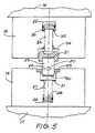
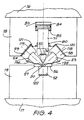
- Figs. 3, 4 and 5 show an embodiment of the die according to the present invention for making racks of the type described, as installed in a press (not shown), having moveable platen 16 and fixed lower platen 17.
- the die comprises upper die member 18 and lower die member 19 secured to respective upper and lower platens 16 and 17 of the press and, in each of the three views depicted in Figs. 3, 4 and 5, is shown in the fully closed position as when rack bar 20 has been fully formed.
- the die has two zones along the length of the rack bar, a gripping zone 21 and a forming zone 22 (Fig. 3).
- Gripping zone 21 comprises an upper gripper 23 and a lower gripper 24 each having semi-circular grooves engaging rack bar blank 20 and loaded respectively by hydraulic cylinders 25 and 26.
- Lower gripper 24 is secured to plunger 27 which is urged upward by piston 28 which is subjected to supply oil pressure (typically 2 to 3.5 MPa) prior to upper gripper 23 coming into contact with rack bar blank 20.
- supply oil pressure typically 2 to 3.5 MPa
- the level of supply oil pressure is set by relief valve 29 when the die is open and by relief valve 30 during gripping. Downward movement of lower gripper 24 is limited by contact of plunger 27 with spacer 31, and upward movement is limited by contact between plunger 27 and keeper 49 (see Figs. 3 and 5).
- Upper gripper 23 is secured to plunger 33 which is urged downward by piston 36 which is subjected to supply oil pressure prior to upper gripper 23 coming into contact with rack bar blank 20. Upward movement of upper gripper 23 is limited by contact of plunger 33 with abutment 34, and downward movement is limited by contact between piston 36 and spacer 35.
- Spacer 31 provides a means of adjusting the stroke of lower gripper 24, and hence the degree of offset produced in the rack bar in plane 43, to suit different designs of rack bars.
- Keeper 49 controls the initial position of lower gripper 24 relative to lower toothed die 52.
- Spacer 35 provides a means of adjusting the stroke of upper gripper 23 to suit different rack bar designs.
- Adjustable packer 51 and 50 provide a means of compensating for the reduction in vertical dimensions of grippers 23 and 24 respectively after refurbishment.
- bottom gripper 24 bottoms out when plunger 27 comes in contact with spacer 31.
- piston 36 commences its displacement upward relative to upper die member 18. The oil displaced by motion of piston 36 is also discharged through relief valve 30.
- pistons 28 and 36 are chosen such that, with the same pressure acting on these pistons, the force exerted by piston 36 will be sufficient to overcome the sum of the force exerted by piston 28 and the force required to shear the offset into rack bar blank 20 in plane 43.
- relief valve 30 Because of the extremely short response time required of relief valve 30 (typically 7 ms to fully open), a pilot operated relief valve can not be used in this application, and relief valve 30 must be of the direct acting type. It is well known in the art that direct acting relief valves are potentially subject to instability and are particularly sensitive to the rate of change of pressure. Accumulator 44 is therefore provided to limit the rate of pressure rise imposed on relief valve 30 to an acceptable limit, typically 1400 MPa/s.
- solenoid valve 47 closes to flow and remains closed until after the die has opened and the formed rack has been ejected by a means that will be described hereafter.
- solenoid valve 47 is opened to flow, the rate at which oil is re-admitted to cylinders 25 and 26 is controlled by adjustable throttle valve 48.
- a cross section of forming zone 22 (Fig. 4), it will be seen that in the fully closed position the rack is contained by four die forming elements: a first forming element in the form of lower toothed die 52, second and third forming elements in the form of rolling dies 53 and 54 and a fourth forming element in the form of the upper die element 55.
- Flank dies 56 and 57 may be made in one part with lower toothed die 52 but are here shown as being made separately for convenience of manufacture and servicing.
- Rolling dies 53 and 54 are supported by fulcrum blocks 58 and 59 which are secured to upper die member 18.
- the upper die element 55 and upper gripper 23 are mechanically separated (see Fig. 3) , and in this embodiment where these components are hydraulically actuated by respective plunger/cylinder arrangements, they are not only separated but are also independently controlled.
- rack bar 20 is firstly gripped by upper gripper 23 and lower gripper 24, as described earlier.
- rolling dies 53 and 54 come into contact with rack bar 20 which is in contact with the top of lower toothed die 52.
- upper die element 55 may not be in contact with rack bar 20, depending on the design of the Y-form cross-section, the rack teeth, and the degree of offset required between the cylindrical portion and the toothed section of the finished rack bar.
- Fig. 6, 7 and 8 are scrap views illustrating the forming of the Y-form portion of the rack, with only one half shown because of symmetry.
- Fig. 6 shows the relative positions of lower toothed die 52, rack bar 20, rolling die 53 and upper die element 55 at the instant lower gripper 24 bottoms out. At this point in the forming cycle, further descent of upper die element 55 relative to lower toothed die 52 is arrested by contact of plunger 71 with stop block 72 and upper gripper 23 (see Fig. 3).
- rolling die 53 moves downward relative to lower toothed die 52 with velocity 60, and develops a rolling motion, illustrated by velocity component 61, about its instantaneous centre with fulcrum block 58 (not shown).
- the resulting motion of rolling die 53 is controlled by a complex force system comprised of normal forging forces 62 and 64; frictional forging forces 63 and 65; normal and frictional forces 68 and 69 respectively; spring force 66 exerted by plate spring 135 (see Fig. 4); and normal forging force 67 acting on upper die element 55.
- Resultant velocity vector 70 represents the velocity of rolling die 53 at the point of contact with upper die element 55, and is substantially parallel to the side flank of upper die element 55 throughout the forming process.
- spacers 118, 119, 120 and 121 which are ground to size to suit each different design of rack bar to be formed. These spacers allow the geometry of the motion of rolling dies 53 and 54 to be varied within limits by changing their instantaneous centres of motion between fulcrum blocks 58 and 59 respectively, and to compensate for elastic deflections in tooling and the upper and lower die members. Spacers 122 and 32 are provided to compensate for the changed vertical dimensions of toothed die 52 and upper die element 55 after refurbishment.
- plunger 73 is displaced upward relative to upper die member 18, causing oil to be displaced from cylinder 75 by piston 74.
- This displaced oil cannot flow into cylinder 83 which has previously been fully extended (piston 84 displaced downward until it contacts spacer 85) by the action of supply oil pressure admitted via solenoid valve 86, adjustable throttle valve 87 and check valve 88.
- the displaced oil is further prevented from flowing to tank 91 by relief valve 89 or to pump 92 by check valve 88.
- Displaced oil is therefore first discharged via port 93 of spool valve 138 to relief valve 29.
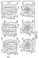
- valve spool 94 is shown in the fully displaced position in Figs. 3 and 10 (c).
- valve spool 94 is displaced fully downward (see Figs. 3 and 10 (a)) by spring 95 acting between collar 96 and housing 97.
- Fig. 10 (b) shows valve spool 94 part way through its stroke. Collar 96 acts against pin 98 which transmits its load to valve spool 94.
- port 93 is open to flow from chamber 99.
- the initial pressure imposed on cylinders 75 and 83, when piston 74 is displaced, is the system pressure set by relief valve 29 (typically 2 to 3.5 MPa).
- valve spool 94 is displaced upward relative to spool valve manifold 90, progressively closing off port 93 to chamber 99.
- the area characteristic of the spool valve may be varied by changing the angular orientation of flat 100 machined in the side of cylindrical valve spool 94, with respect to port 93. This is achieved by rotating cylindrical housing 97 about axis 101. Pin 102 in valve spool 94 engages slot 137 in housing 97 and connects housing 97 with valve spool 94, hence rotation of housing 97 imparts the same rotation to valve spool 94. In this way, all or part of flat 100 may be presented to port 93, thus providing the desired variable area characteristic for the spool valve.
- Figs. 10 (d), 10 (e) and 10 (f), which are sectional views in plane E-E of figures 10 (a), 10 (b), and 10 (c), show in plan view different angular orientations of flat 100 with respect to port 93.
- Valve spool 94 is displaced upward by contact with spacer 103, which is connected to lower die member 19 by striker 104, during die closure.
- spacer 103 By varying the thickness of spacer 103, the process of varying the pressure in cylinders 75 and 83 as the die closes can be initiated at different stages of the forming cycle, as dictated by rack bar designs.
- the rate at which pressure increases during die closure is varied by changing the orientation of flat 100 relative to port 93, as earlier described.
- valve spool 94 fully closes off port 93 to flow. Any further oil displaced must be discharged via relief valve 89, which is similar in construction and principle of operation to that of relief valve 30 earlier described. Once the discharge pressure set by relief valve 89 is reached, oil is discharged via port 105 to relief valve 29 and thence to tank 91. Accumulator 107 is provided, as is the case of accumulator 44, to limit the rate of pressure rise to an acceptable level.
- Accumulator 108 of the pre-charged gas-bladder type, is provided to accommodate the large instantaneous flow rate discharged via port 93 (typically 600 l/min). Accumulators 44 and 107 are without entrained gases or bladder separation and rely on the compressibility effects of the oil to be used to limit the rate of pressure rise imposed on relief valves 30 and 89 respectively.
- Oil displaced from cylinder 113 by upward motion of valve spool 94 is discharged via drillings 115 and 117 into chamber 116 and thence to drain via port 114.
- FIG. 3 Other hydraulic elements shown in Fig. 3 include suction strainer 109, oil tank breather 110, oil cooler 111 and relief check 112.
- Relief check 112 is provided to create a flow path in the unlikely event that solenoid valve 86 is open to flow, all cylinders are fully extended and valve spool 94 is in its uppermost position (eg: die closed during set-up, or valve spool jammed), thereby shutting off flow from port 93. Without relief check 112, pump 92 would stall and rapidly overheat. In the normal course of events, relief check 112 is unnecessary.
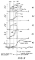
- Figs. 9 (a) through 9 (e) represent in each case the opening ⁇ between upper die member 18 and lower die member 19.
- Forces F 23 and F 24 in Fig. 9(a) are those forces exerted on rack bar 20 by upper gripper 23 and lower gripper 24 respectively.
- Force F 55 in Fig. 9 (b) is that exerted on rack bar 20 by upper die element 55
- Force F 73 is that exerted on end stop 76 by plunger 73.
- Pressures P 25 and P 26 in Fig. 9 (c) denote pressures developed in cylinders 25 and 26 respectively.
- Pressures P 75 and P 83 in Fig. 9 (d) denote pressures developed in cylinders 75 and 83 respectively.
- 't' denotes time in Fig. 9 (e).
- gripping forces F 23 and F 24 are the shear force in rack bar 20 in plane 43, and the increased value of bottom gripper force F 24 , is reacted partly by spacer 31 and partly by the force of pressure P 26 acting on piston 28.
- force F 23 and F 24 may be easily varied according to the present invention by adjusting relief valve 30 to the requisite value to prevent extrusion of metal from forming zone 21 through grippers 23 and 24.
- gripping forces F 23 and F 24 reduce immediately to zero (point 131).
- the formed rack bar 20 is then extracted from tooth die 52 by the clamping action of rolling dies 53 and 54 on stem 14 of the Y-form. This clamping action arises from the forces 66 exerted by spring-steel plated springs 135 and 136 on rolling dies 53 and 54 respectively.
- solenoid valve 86 Activation of solenoid valve 86 may be either by a push-button actuated by the operator in a manual loaded die, or may be actuated automatically by the control system in a die incorporating a fully automatic loading system.
- solenoid valve 47 remains closed to flow until after solenoid valve 86 has opened to flow and rack bar 20 has been ejected by upper die element 55. Thereafter, solenoid valve 47 is opened to flow, cylinders 25 and 26 extend upper and lower grippers 23 and 24 respectively by applying supply oil pressure to pistons 36 and 28 respectively. The rate at which grippers 23 and 24 are extended is set by adjustable throttle valve 48.
- Figs. 9 (e) and 9 (d) illustrate the essential difference between the pressure characteristics required of elements in gripping zone 21 and forming zone 22 respectively.
- Fig. 9 (d) shows that P 75 and P 83 start to increase at instant (i).
- piston 74 is the first piston displaced in the forming cycle. It is not necessary to develop full clamping force on end stop 76 until the last 2 - 3 mm of die closure, hence the rate of pressure increase in the early stages of die closure is initially high, due to the step change in oil flow velocity but limited by compression of the oil in accumulator 107, then low as relatively unrestricted flow of oil through port 93 is established, and still later exponentially increasing until the pressure indicated by point 132 is reached, at which point port 93 is fully closed to flow by valve spool 94, and relief valve 89 opens.
- FIG. 9 (d) illustrates an alternative combination of rate of rise of pressure and relief valve set point pressure, curve 133, is easily varied without having to remove the die from service or machine any components.
- Forces F 55 and F 73 in Fig. 9 (b) correspond to pressures P 83 and P 75 respectively in Fig. 9 (d).
- Clamping force F 73 is smaller because the area of piston 74 is made smaller than that of piston 84.
- the peak design pressures in cylinders 75 and 83 are in the range 32 to 42 MPa, with forces 10 to 14 tonnes and 80 to 110 tonnes respectively.
- pressures P 25 and P 26 which begin to increase at instant (ii), must increase rapidly to the maximum value indicated by point 134 in Fig. 9 (c) in order to firmly clamp rack bar 20 prior to shearing the offset in plane 43 and commencing substantial forming of the Y-form portion.
- the rate of pressure rise, as described earlier, is limited by accumulator 44, and relief valve 30 limits the operating pressures P 25 and P 26 acting on pistons 36 and 28 respectively.
- Fig. 9 (e) shows two typical time displacement curves for a die according to the present invention.
- the typical values for a screw press and crank press are illustrated by the solid curve and dashed curves respectively. Note that the contact time between rack bar and forming elements is shorter for screw presses, which can be of benefit for high volume production applications, but provided the longer contact time arising from use of a crank press does not lead to any significant reduction in tool life, a crank press can be used.
Landscapes
- Engineering & Computer Science (AREA)
- Mechanical Engineering (AREA)
- Forging (AREA)
Description
Claims (10)
- A die for forming a toothed portion (1) of a steering rack bar from a blank (20) by forging, the toothed portion having a face with teeth (8) and at least two longitudinally extending guide faces (4, 5), the die comprising first and second die members (18, 19) and a group of first, second, third and fourth forming elements relatively moveable to converge on the blank when placed in the die, the first forming element (52) being part of the second die member and having a form on one face corresponding to the obverse form of the teeth, the second (53) and third (54) forming elements being part of the first die member and having forming faces adapted to form the longitudinally extending guide faces of the toothed portion, the fourth forming element (55) connected to a first bias means and slideable relative to the first die member between the second and third forming elements and adapted to form a surface of the toothed portion lying between the guide faces and opposite the teeth, the first bias means allowing movement of the fourth forming element away from the blank under loads imposed during forging, the die further comprising a gripper system for longitudinally constraining the blank during forging, the gripper system comprising opposed first and second grippers (23, 24) loaded radially against a non-formed surface of the blank during forging, the first gripper connected to a second bias means and slideable relative to the first die member and the second gripper connected to a third bias means and slideable relative to the second die member, characterised in that the first bias means is mechanically separated from the second bias means.
- A die as claimed in claim 1 wherein the first bias means and the second bias means are hydraulic actuators.
- A die as claimed in claim 1 wherein the third bias means is a hydraulic actuator.
- A die as claimed in claim 1 wherein the second and third bias means are hydraulic actuators and are hydraulically interconnected.
- A die as claimed in claim 1 wherein at least two of the first, second and third bias means are hydraulic actuators and the magnitude and instant of application of the pressure in at least one hydraulic actuator is separately controlled.
- A die as claimed in claim 1 wherein the die further comprises a restraint means for longitudinally restraining the blank during forging, the restraint means pivotally mounted about an axis substantially perpendicular to the longitudinal axis of the blank and having a face substantially perpendicular to the longitudinal axis of the blank, the restraint means clamped by a clamp means against a fixed stop portion of the second die member during closure of the die.
- A die as claimed in claim 1 wherein at least one of the first, second or third bias means is a hydraulic actuator in which the pressure applied thereto is controlled as a function of the relative displacement of the first and second die members (18, 19).
- A die as claimed in claim 1, wherein at least one of the first, second and third bias means is a hydraulic actuator controlled by at least one pressure relief valve.
- A die as claimed in claim 1, wherein at least one of the first, second and third bias means is a hydraulic actuator controlled by at least one pressure relief valve with at least one accumulator connected to the hydraulic connection between the hydraulic actuator and the relief valve.
- A die for forming a toothed portion (1) of a steering rack bar from a blank (20) by forging, the toothed portion having a face with teeth (8) and at least two longitudinally extending guide faces, the die comprising first and second die members (18, 19) and a group of first (52), second (53), third (54) and fourth (55) forming elements relatively moveable to converge on the blank when placed in the die, the first forming element (52) being part of the second die member and having a form on one face corresponding to the obverse form of the teeth, the second (53) and third (54) forming elements being part of the first die member and having faces adapted to form the longitudinally extending guide faces of the toothed portion, and the fourth forming element (55) connected to a first hydraulic actuator and slideable relative to the first die member between the second (53) and third (54) forming elements and adapted to form a surface of the toothed portion lying between the guide faces and opposite the teeth, the first hydraulic actuator allowing movement of the fourth forming element (55) away from the blank under loads imposed during forging, characterised in that the magnitude and the instant of application of pressure in the first hydraulic actuator is controlled.
Applications Claiming Priority (4)
| Application Number | Priority Date | Filing Date | Title |
|---|---|---|---|
| AUPM302693 | 1993-12-16 | ||
| AUPM3026A AUPM302693A0 (en) | 1993-12-16 | 1993-12-16 | Apparatus for manufacturing steering rack bars |
| AUPM3026/93 | 1993-12-16 | ||
| PCT/AU1994/000775 WO1995016529A1 (en) | 1993-12-16 | 1994-12-16 | Apparatus for manufacturing steering rack bars |
Publications (3)
| Publication Number | Publication Date |
|---|---|
| EP0738191A1 EP0738191A1 (en) | 1996-10-23 |
| EP0738191A4 EP0738191A4 (en) | 1997-02-05 |
| EP0738191B1 true EP0738191B1 (en) | 2000-03-15 |
Family
ID=3777651
Family Applications (1)
| Application Number | Title | Priority Date | Filing Date |
|---|---|---|---|
| EP95904353A Expired - Lifetime EP0738191B1 (en) | 1993-12-16 | 1994-12-16 | Apparatus for manufacturing steering rack bars |
Country Status (11)
| Country | Link |
|---|---|
| US (1) | US5862701A (en) |
| EP (1) | EP0738191B1 (en) |
| JP (1) | JP3351793B2 (en) |
| KR (1) | KR100287224B1 (en) |
| CN (1) | CN1058433C (en) |
| AU (1) | AUPM302693A0 (en) |
| BR (1) | BR9408222A (en) |
| CA (1) | CA2177834C (en) |
| DE (1) | DE69423518T2 (en) |
| ES (1) | ES2143040T3 (en) |
| WO (1) | WO1995016529A1 (en) |
Cited By (1)
| Publication number | Priority date | Publication date | Assignee | Title |
|---|---|---|---|---|
| DE102010036609A1 (en) | 2010-07-26 | 2012-01-26 | Thyssenkrupp Presta Ag | Die for forging a toothed portion of a rack of a steering device |
Families Citing this family (20)
| Publication number | Priority date | Publication date | Assignee | Title |
|---|---|---|---|---|
| AUPN729495A0 (en) * | 1995-12-21 | 1996-01-18 | A.E. Bishop & Associates Pty Limited | Method and apparatus for manufacturing steering rack bar |
| DE19839428A1 (en) | 1998-08-29 | 2000-03-02 | Zahnradfabrik Friedrichshafen | Method of manufacturing a rack and embossing device for carrying out the method |
| KR100888192B1 (en) * | 2001-03-22 | 2009-03-12 | 비숍 이노베이션 리미티드 | Method and apparatus for the production of forged racks |
| DE10203888A1 (en) * | 2002-01-31 | 2003-08-21 | Zf Lenksysteme Gmbh | Method and device for manufacturing a rack |
| US20070175695A1 (en) * | 2003-09-22 | 2007-08-02 | Dishop Steering Technology Limited | Steering gear |
| BRPI0414291A (en) * | 2003-09-23 | 2006-11-07 | Bishop Innovation Ltd | steering rack for a rack and pinion type steering mechanism and method of manufacture |
| CA2548148A1 (en) * | 2003-12-04 | 2005-06-16 | Bishop Innovation Limited | Steering rack manufacture |
| JP2008510070A (en) * | 2004-08-18 | 2008-04-03 | ビショップ イノヴェーション リミテッド | Method for producing hardened forged steel member |
| WO2006099661A1 (en) * | 2005-03-23 | 2006-09-28 | Bishop Innovation Limited | Steering rack and method of manufacture thereof |
| EP2464476A1 (en) * | 2009-08-12 | 2012-06-20 | Bishop Steering Technology Pty Ltd | Forging die apparatus for steering racks |
| KR101754851B1 (en) * | 2009-11-26 | 2017-07-06 | 가부시키가이샤 고슈 | Apparatus for manufacturing plate-shaped gear teeth member |
| WO2011140580A1 (en) * | 2010-05-10 | 2011-11-17 | Bishop Steering Technology Pty Ltd | Die apparatus for forging steering racks |
| CN102305707B (en) * | 2011-08-08 | 2013-07-10 | 宁波南方塑料模具有限公司 | Mould hydraulic tester |
| DE102011115048A1 (en) * | 2011-10-07 | 2013-04-11 | Mahle International Gmbh | A forging apparatus for producing a piston blank and a method for producing the piston blank using the forging apparatus |
| JP6408819B2 (en) | 2014-07-28 | 2018-10-17 | 高周波熱錬株式会社 | Method for producing hollow rack bar |
| CN109996619B (en) | 2016-11-27 | 2021-03-30 | 毕晓普操纵技术私人股份公司 | Die equipment for forging steering racks |
| CN107972310A (en) * | 2017-11-27 | 2018-05-01 | 吕言 | Press machine system, control method and balancing device |
| CN110842131B (en) * | 2019-12-02 | 2020-12-15 | 海汇汽车制造有限公司 | A automatic preparation rack machine for mill |
| CN116274597B (en) * | 2023-05-22 | 2023-07-21 | 常州忠正汽车零部件有限公司 | Stamping forming equipment for automobile seat frame |
| CN117564137B (en) * | 2024-01-15 | 2024-04-26 | 德阳华智精密科技有限公司 | Lamp pole dovetail groove forming die |
Family Cites Families (7)
| Publication number | Priority date | Publication date | Assignee | Title |
|---|---|---|---|---|
| US2153839A (en) * | 1936-02-11 | 1939-04-11 | Fritz Singer | Metalworking |
| DE2306566C2 (en) * | 1973-02-10 | 1983-11-17 | Pahnke Engineering GmbH & Co KG, 4000 Düsseldorf | Hydraulic drive for forging machines |
| DE3202254C2 (en) * | 1982-01-25 | 1986-02-20 | Zahnradfabrik Friedrichshafen Ag, 7990 Friedrichshafen | Method and device for producing a toothed rack |
| JPS59501004A (en) * | 1982-06-02 | 1984-06-07 | ビシヨツプ,ア−サ− ア−ネスト | Steering rack bar manufacturing method and device |
| BR8307391A (en) * | 1982-06-04 | 1984-05-08 | Bishop Arthur E | TEMPLATE FOR MOLDING A PART OF A RACK BAR AND METHOD FOR MANUFACTURING A RACK BAR |
| JPS597456A (en) * | 1982-07-07 | 1984-01-14 | Nissan Motor Co Ltd | Rack shaft slug of variable ratio steering device |
| JPS5999043U (en) * | 1982-12-20 | 1984-07-04 | 日産自動車株式会社 | Mold for easy tooth preparation |
-
1993
- 1993-12-16 AU AUPM3026A patent/AUPM302693A0/en not_active Abandoned
-
1994
- 1994-12-16 KR KR1019960703167A patent/KR100287224B1/en not_active Expired - Fee Related
- 1994-12-16 EP EP95904353A patent/EP0738191B1/en not_active Expired - Lifetime
- 1994-12-16 CN CN94194932A patent/CN1058433C/en not_active Expired - Fee Related
- 1994-12-16 JP JP51642195A patent/JP3351793B2/en not_active Expired - Fee Related
- 1994-12-16 DE DE69423518T patent/DE69423518T2/en not_active Expired - Lifetime
- 1994-12-16 WO PCT/AU1994/000775 patent/WO1995016529A1/en not_active Ceased
- 1994-12-16 US US08/652,466 patent/US5862701A/en not_active Expired - Lifetime
- 1994-12-16 CA CA002177834A patent/CA2177834C/en not_active Expired - Fee Related
- 1994-12-16 BR BR9408222A patent/BR9408222A/en not_active IP Right Cessation
- 1994-12-16 ES ES95904353T patent/ES2143040T3/en not_active Expired - Lifetime
Cited By (4)
| Publication number | Priority date | Publication date | Assignee | Title |
|---|---|---|---|---|
| DE102010036609A1 (en) | 2010-07-26 | 2012-01-26 | Thyssenkrupp Presta Ag | Die for forging a toothed portion of a rack of a steering device |
| WO2012013284A1 (en) | 2010-07-26 | 2012-02-02 | Thyssenkrupp Presta Aktiengesellschaft | Die for forging |
| US9149860B2 (en) | 2010-07-26 | 2015-10-06 | Thyssenkrupp Presta Aktiengesellschaft | Die for forging |
| DE102010036609B4 (en) * | 2010-07-26 | 2016-08-11 | Thyssenkrupp Presta Aktiengesellschaft | Die for forging a toothed portion of a rack of a steering device |
Also Published As
| Publication number | Publication date |
|---|---|
| DE69423518T2 (en) | 2000-11-09 |
| DE69423518D1 (en) | 2000-04-20 |
| EP0738191A4 (en) | 1997-02-05 |
| KR100287224B1 (en) | 2001-11-22 |
| ES2143040T3 (en) | 2000-05-01 |
| JPH09506550A (en) | 1997-06-30 |
| CN1058433C (en) | 2000-11-15 |
| AUPM302693A0 (en) | 1994-01-20 |
| EP0738191A1 (en) | 1996-10-23 |
| BR9408222A (en) | 1997-08-26 |
| CA2177834A1 (en) | 1995-06-22 |
| JP3351793B2 (en) | 2002-12-03 |
| US5862701A (en) | 1999-01-26 |
| CN1142792A (en) | 1997-02-12 |
| CA2177834C (en) | 2004-04-27 |
| KR960706380A (en) | 1996-12-09 |
| WO1995016529A1 (en) | 1995-06-22 |
Similar Documents
| Publication | Publication Date | Title |
|---|---|---|
| US5862701A (en) | Apparatus for manufacturing steering rack bars | |
| CA2023675C (en) | Apparatus and method for forming a tubular frame member | |
| US5353618A (en) | Apparatus and method for forming a tubular frame member | |
| US6250128B1 (en) | Forging die and upset forging method | |
| US7165437B2 (en) | Mechanical press device | |
| EP2384834B1 (en) | Hydraulic die cushion with a hydraulic cylinder | |
| US4715210A (en) | Method for making steering rack bars | |
| US20100043519A1 (en) | Method and device for controlling the synchronization of cylinder/piston units and for reducing pressure peaks during forming and/or fineblanking on a fineblanking or stamping press | |
| CN104772422B (en) | Forging device | |
| EP1758697A2 (en) | Method and device for cutting high-tensile sheet metal, and press | |
| AU676628B2 (en) | Apparatus for manufacturing steering rack bars | |
| CN1089653C (en) | Method of hot pressing workpieces | |
| EP2080573A2 (en) | Apparatus for manufacturing metal articles, in particular of light alloy | |
| US7124618B1 (en) | Clamp assembly for hydroforming die | |
| US5819573A (en) | Hydraulic forming of workpieces from sheet metal | |
| US20120137747A1 (en) | Forging die apparatus for steering racks | |
| DE102023105367B4 (en) | Hydraulic forming machine for workpiece forming, hydraulic control unit and method for controlling a hydraulic cylinder of a hydraulic forming machine | |
| WO2005075183A1 (en) | Press comprising a locked slide | |
| CA1051229A (en) | Cam actuated ejector mechanisms for presses | |
| EP2428290A1 (en) | A cushioning arrangement for presses | |
| DE102023113473B4 (en) | Hydraulic forming machine for workpiece forming, hydraulic control unit and method for controlling a hydraulic cylinder of a hydraulic forming machine | |
| JPH0790396B2 (en) | Press machine | |
| GB2048736A (en) | Warm Forging of Connecting Rod Caps | |
| US2725025A (en) | Blankholder actuating mechanism | |
| RU2222399C1 (en) | Apparatus for hydraulic shaping of tubular blanks |
Legal Events
| Date | Code | Title | Description |
|---|---|---|---|
| PUAI | Public reference made under article 153(3) epc to a published international application that has entered the european phase |
Free format text: ORIGINAL CODE: 0009012 |
|
| 17P | Request for examination filed |
Effective date: 19960702 |
|
| AK | Designated contracting states |
Kind code of ref document: A1 Designated state(s): DE ES FR GB IT SE |
|
| A4 | Supplementary search report drawn up and despatched |
Effective date: 19961220 |
|
| AK | Designated contracting states |
Kind code of ref document: A4 Designated state(s): DE ES FR GB IT SE |
|
| RAP1 | Party data changed (applicant data changed or rights of an application transferred) |
Owner name: BISHOP STEERING PTY LIMITED |
|
| GRAG | Despatch of communication of intention to grant |
Free format text: ORIGINAL CODE: EPIDOS AGRA |
|
| 17Q | First examination report despatched |
Effective date: 19990312 |
|
| GRAG | Despatch of communication of intention to grant |
Free format text: ORIGINAL CODE: EPIDOS AGRA |
|
| GRAH | Despatch of communication of intention to grant a patent |
Free format text: ORIGINAL CODE: EPIDOS IGRA |
|
| GRAH | Despatch of communication of intention to grant a patent |
Free format text: ORIGINAL CODE: EPIDOS IGRA |
|
| GRAA | (expected) grant |
Free format text: ORIGINAL CODE: 0009210 |
|
| AK | Designated contracting states |
Kind code of ref document: B1 Designated state(s): DE ES FR GB IT SE |
|
| ITF | It: translation for a ep patent filed | ||
| REF | Corresponds to: |
Ref document number: 69423518 Country of ref document: DE Date of ref document: 20000420 |
|
| ET | Fr: translation filed | ||
| REG | Reference to a national code |
Ref country code: ES Ref legal event code: FG2A Ref document number: 2143040 Country of ref document: ES Kind code of ref document: T3 |
|
| PLBE | No opposition filed within time limit |
Free format text: ORIGINAL CODE: 0009261 |
|
| STAA | Information on the status of an ep patent application or granted ep patent |
Free format text: STATUS: NO OPPOSITION FILED WITHIN TIME LIMIT |
|
| 26N | No opposition filed | ||
| REG | Reference to a national code |
Ref country code: GB Ref legal event code: IF02 |
|
| PGFP | Annual fee paid to national office [announced via postgrant information from national office to epo] |
Ref country code: SE Payment date: 20060929 Year of fee payment: 13 |
|
| PGFP | Annual fee paid to national office [announced via postgrant information from national office to epo] |
Ref country code: ES Payment date: 20061201 Year of fee payment: 13 |
|
| EUG | Se: european patent has lapsed | ||
| PG25 | Lapsed in a contracting state [announced via postgrant information from national office to epo] |
Ref country code: SE Free format text: LAPSE BECAUSE OF NON-PAYMENT OF DUE FEES Effective date: 20071217 |
|
| REG | Reference to a national code |
Ref country code: ES Ref legal event code: FD2A Effective date: 20071217 |
|
| PGFP | Annual fee paid to national office [announced via postgrant information from national office to epo] |
Ref country code: IT Payment date: 20081024 Year of fee payment: 15 |
|
| PG25 | Lapsed in a contracting state [announced via postgrant information from national office to epo] |
Ref country code: ES Free format text: LAPSE BECAUSE OF NON-PAYMENT OF DUE FEES Effective date: 20071217 |
|
| PGFP | Annual fee paid to national office [announced via postgrant information from national office to epo] |
Ref country code: FR Payment date: 20081127 Year of fee payment: 15 |
|
| PGFP | Annual fee paid to national office [announced via postgrant information from national office to epo] |
Ref country code: GB Payment date: 20081209 Year of fee payment: 15 |
|
| GBPC | Gb: european patent ceased through non-payment of renewal fee |
Effective date: 20091216 |
|
| REG | Reference to a national code |
Ref country code: FR Ref legal event code: ST Effective date: 20100831 |
|
| PG25 | Lapsed in a contracting state [announced via postgrant information from national office to epo] |
Ref country code: FR Free format text: LAPSE BECAUSE OF NON-PAYMENT OF DUE FEES Effective date: 20091231 |
|
| PG25 | Lapsed in a contracting state [announced via postgrant information from national office to epo] |
Ref country code: GB Free format text: LAPSE BECAUSE OF NON-PAYMENT OF DUE FEES Effective date: 20091216 |
|
| PG25 | Lapsed in a contracting state [announced via postgrant information from national office to epo] |
Ref country code: IT Free format text: LAPSE BECAUSE OF NON-PAYMENT OF DUE FEES Effective date: 20091216 |
|
| PGFP | Annual fee paid to national office [announced via postgrant information from national office to epo] |
Ref country code: DE Payment date: 20140114 Year of fee payment: 20 |
|
| REG | Reference to a national code |
Ref country code: DE Ref legal event code: R071 Ref document number: 69423518 Country of ref document: DE |