CN104772422B - Forging device - Google Patents
Forging device Download PDFInfo
- Publication number
- CN104772422B CN104772422B CN201510018629.3A CN201510018629A CN104772422B CN 104772422 B CN104772422 B CN 104772422B CN 201510018629 A CN201510018629 A CN 201510018629A CN 104772422 B CN104772422 B CN 104772422B
- Authority
- CN
- China
- Prior art keywords
- punch
- die
- valve
- holder
- bypass valve
- Prior art date
- Legal status (The legal status is an assumption and is not a legal conclusion. Google has not performed a legal analysis and makes no representation as to the accuracy of the status listed.)
- Expired - Fee Related
Links
Images


Classifications
-
- B—PERFORMING OPERATIONS; TRANSPORTING
- B21—MECHANICAL METAL-WORKING WITHOUT ESSENTIALLY REMOVING MATERIAL; PUNCHING METAL
- B21J—FORGING; HAMMERING; PRESSING METAL; RIVETING; FORGE FURNACES
- B21J5/00—Methods for forging, hammering, or pressing; Special equipment or accessories therefor
- B21J5/008—Incremental forging
-
- B—PERFORMING OPERATIONS; TRANSPORTING
- B21—MECHANICAL METAL-WORKING WITHOUT ESSENTIALLY REMOVING MATERIAL; PUNCHING METAL
- B21J—FORGING; HAMMERING; PRESSING METAL; RIVETING; FORGE FURNACES
- B21J9/00—Forging presses
- B21J9/10—Drives for forging presses
- B21J9/12—Drives for forging presses operated by hydraulic or liquid pressure
-
- B—PERFORMING OPERATIONS; TRANSPORTING
- B30—PRESSES
- B30B—PRESSES IN GENERAL
- B30B15/00—Details of, or accessories for, presses; Auxiliary measures in connection with pressing
- B30B15/06—Platens or press rams
- B30B15/065—Press rams
-
- B—PERFORMING OPERATIONS; TRANSPORTING
- B30—PRESSES
- B30B—PRESSES IN GENERAL
- B30B15/00—Details of, or accessories for, presses; Auxiliary measures in connection with pressing
- B30B15/16—Control arrangements for fluid-driven presses
- B30B15/18—Control arrangements for fluid-driven presses controlling the reciprocating motion of the ram
Abstract
A forging apparatus includes an oil pressure circuit (70) for supporting a selected one or more of a plurality of punches (26, 28) via hydraulic pressure, the hydraulic pressure being released just before a die set (12) reaches a bottom dead center during forging, wherein an impact member (40) is provided on a die holder (14), and a bypass valve (50) is provided on a punch holder (16) for opening and closing a flow path of the oil pressure circuit. During forging, immediately before the die holder reaches the bottom dead center, the striking member moves a valve element (51) of the bypass valve in a valve opening direction, thereby mechanically opening a flow path of the oil pressure circuit.
Description
Technical Field
The invention relates to a forging apparatus of this type: the forging apparatus includes a plurality of punches arranged such that a selected one or more of the punches is hydraulically supported and the hydraulic pressure is released immediately before the selected punch reaches the bottom dead center.
Background
In extrusion processing, a billet or workpiece is placed on a die and a punch is forced toward the die, thereby subjecting the workpiece to plastic deformation. During this time, the die assembly composed of the die and the punch is subjected to a large load, and therefore, the life of the die assembly is relatively short. For example, as disclosed in japanese patent (JP-B2)2534899, there is known a technique of extending the life of a die assembly, in which the pressure on a presser member is released immediately before the end of an extrusion process, thereby reducing the maximum load applied to the die assembly.
More specifically, the extrusion apparatus disclosed in JP 2534899B2 includes an upper die set equipped with a plurality of punches having cylindrical punches and presser members slidably disposed in shaft holes of the cylindrical punches or around outer peripheral surfaces thereof. The cylindrical punch is fixed to the upper die set. The presser members are vertically movable relative to the die set and are supported by oil hydraulic cylinders. The hydraulic cylinder is connected to a hydraulic pressure supply pipe and a hydraulic pressure discharge pipe, each of which is connected to a hydraulic power source via a solenoid control valve. Before the extrusion process is finished, the solenoid control valve is operated to switch to a position where the hydraulic pressure is released from the oil hydraulic cylinder. Thus, the maximum load applied to the mold assembly is reduced, and the life of the mold assembly is correspondingly extended.
The extrusion process includes a cold forging process performed at room temperature and a hot forging process performed at high temperature. In the cold forging process, the temperature change does not cause any problem, and a long processing time can be accepted. On the other hand, in hot forging processing, since plastic working of the workpiece should be completed with the workpiece still in a prescribed temperature range, the working time should preferably be as short as possible.
The solenoid control valve includes an electromagnetic coil (solenoid) and a plunger that moves when the solenoid coil is energized. Upon receiving the valve opening signal, the solenoid is energized, thereby generating electromagnetic force to move the plunger in a desired direction. A common solenoid controlled valve involves a time delay or hysteresis on the order of 0.1 seconds due to the accumulation of the time period required for energization, magnetization and movement. Special solenoid controlled valves designed to meet high speed operation can reduce valve opening time. However, such special solenoid controlled valves are very expensive and the time reduction effect achieved by the same valve is small compared to the cost increase.
It will be appreciated that a technique employing a solenoid control valve such as that disclosed in JP 2534899B2 is suitable for use in cold forging work in which the pressing speed is slow. However, in the hot forging process performed at a high pressing speed, the valve employed is required to operate instantaneously in the order of 0.01 second. Thus, if a solenoid control valve having a response time of the order of 0.1 second is used in such a hot forging process, the valve opening operation may not be performed in time, which results in failure to release the hydraulic pressure at an appropriate timing.
Disclosure of Invention
Accordingly, an object of the present invention is to provide a forging apparatus capable of releasing hydraulic pressure with improved reliability even when used in ultra-high speed forging processing.
According to the present invention, there is provided a forging apparatus including: a die set having a plurality of punches; and an oil pressure circuit for supporting any one of the plurality of punches via hydraulic pressure, the hydraulic pressure being released immediately before the die set reaches a bottom dead center during forging, characterized in that: the forging apparatus includes a bypass valve for opening and closing a flow path of the oil pressure circuit; the die set includes a die holder supporting a die and a punch holder equipped with the plurality of punches and relatively movable toward and away from the die holder; an impact member is relatively immovably disposed on one of the die holder and the punch holder, and the bypass valve is relatively immovably disposed on the other of the die holder and the punch holder; and during forging, immediately before the die set reaches the bottom dead center, the striking member moves a valve element of the bypass valve in a valve opening direction, thereby mechanically opening the flow path of the oil pressure circuit.
With this arrangement, since the hydraulic pressure acting on the specific punch during forging is released immediately before the die set reaches the bottom dead center, the material of the workpiece being forged is allowed to flow from the adjacent area to the area facing the specific punch. By virtue of this flow splitting technique, the maximum load acting on the die assembly at the end of the forging process can be reduced, and an extended die assembly life can be achieved. Also, the bypass valve is mechanically switched when the valve element is moved or displaced immediately before the die set reaches the bottom dead center. Therefore, the bypass valve can be operated without time lag, which would occur in the case of a solenoid control valve, and can release the hydraulic pressure at an appropriate timing even when applied in a forging process performed at a very high pressing speed, such as hot forging.
Preferably, the bypass valve is provided on the punch holder. Conversely, if the bypass valve is disposed on the die holder, the bypass valve is positioned away from the punch. This arrangement requires a long hydraulic circuit connecting the ram and the bypass valve, which reduces the responsiveness of the bypass valve. Also, at least a part of the oil pressure circuit should be formed of a flexible pipe. According to the present invention, since the bypass valve is provided on the punch holder, the bypass valve can be closer to the punch, which improves the responsiveness of the bypass valve and eliminates the need for using a flexible tube.
Preferably, the striking member includes a height adjustment mechanism for adjusting a height of the striking member. By virtue of this arrangement, when the setting or arrangement of the die set has been changed, it is possible to easily place the impact member at a desired height required for the die set.
Preferably, the punch supported by the hydraulic pressure is a punch designed to shape a portion of the entire area of the workpiece where the accuracy requirement is the lowest. Since only a limited portion of the workpiece is used to reduce the load on the entire area of the workpiece, the remaining portion of the workpiece can be forged with improved accuracy.
Drawings
FIG. 1 is an elevational view, partially in section, of a forging apparatus according to a preferred embodiment of the invention;
FIG. 2 is a cross-sectional view of a bypass valve included in the forging apparatus;
FIG. 3 is an elevational view, partially in section, of an impact member of the forging apparatus;
FIGS. 4A and 4B are cross-sectional views illustrating the operation of the bypass valve;
FIGS. 5A-5C are diagrams illustrating a series of forging steps according to the present invention; and
FIG. 6 is a front view, partially in section, of a modified impact member.
Detailed Description
Preferred structural embodiments of the present invention will be described in more detail below, by way of example only, with reference to the accompanying drawings.
As shown in fig. 1, the forging apparatus 10 includes a die set 12 as a main structural element. The die set 12 includes a die holder 14; a punch holder 16, the punch holder 16 being disposed above the die holder 14; guide rods 18, the guide rods 18 extending vertically upward from corners of the die holder 14; and guide bushes 19 extending vertically downward from respective corners of the punch holder 16 so as to be slidably fitted around the respective guide rods 18.
The punch holder 16 can be moved up and down precisely relative to the die holder 14 by means of a guide sleeve 19 which is guided thereby by guide rods 18. In the illustrated embodiment, the die holder 14 is a stationary component and the punch holder 16 is a movable component. Alternatively, the die holder 14 may constitute a movable member, in which case the punch holder constitutes a fixed member. As another alternative, both the die holder 14 and the punch holder 16 may constitute movable components. In any event, the die set 12 is configured to ensure that the punch holder 16 and the die holder 14 can move relative to each other for a reciprocating motion having a bottom dead center.
The die 22 is placed on the die holder 14 via the lower holder block 21. The die 22 is held in place by a die holder 23.
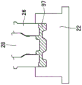
The first punch 26 is disposed on the die holder 16 via the upper holder block 25. The first punch 26 is held in place by a punch holder 27. The second punch 28 is disposed vertically through the first punch 26. The second punch 28 has a base (upper end in fig. 1) fixed to a rectangular punching plate 29. The punch plate 29 is movably accommodated in a recess 31 formed in the upper holder block 25.
The punch holder 16 has an annular cylinder hole 32 formed inside thereof, and an annular piston 33 is slidably inserted in the annular cylinder hole 32. A plurality (two shown) of piston rods 34 extend vertically downward from the piston 33. Piston rod 34 has a distal end (lower end in fig. 1) fixed to punch plate 29. With the piston 33 fully accommodated in the cylinder bore 32, the upper open end of the cylinder bore 32 is closed by the cap 35, so that a closed oil chamber 36 is defined between the cap 35 and the piston 33.
The impact member 40 is mounted on the die holder 14 and extends in a vertically upward direction. The bypass valve 50 is mounted on the punch holder 16 so as to be coaxial with the impact member 40. The bypass valve 50 has a valve element 51 projecting in a vertically downward direction.
The inside of the storage tank 62 holds the working liquid 61, and is arranged outside the die holder 14. The storage tank 62 is a closed container and has an upper portion connected to an air pipe 64 extending from a high-pressure air source 63. The air pipe 64 is provided with a pressure regulating valve 65 for regulating the secondary air pressure to a constant value. The pressure regulating valve 65 may be provided at any position on the air tube 64, the air tube 64 including a base end, a distal end, and an intermediate portion between the base end and the distal end of the air tube 64.
The storage groove 62 and the oil chamber 36 are connected via an oil pressure circuit 70. The oil pressure circuit 70 includes: a first oil path 71, the first oil path 71 directly connecting the storage groove 62 and the oil chamber 36; a first check valve 72 provided in the first oil passage 71 and configured to allow the working fluid 61 to flow from the storage tank 62 to the oil chamber 36 in only one direction; a bypass path 73, the bypass path 73 being connected to the first oil passage 71 so as to bypass the first check valve 72; a relief valve 74 that is provided in the bypass path 73 and is configured to open when the pressure on the oil chamber 36 side exceeds a prescribed pressure (e.g., a maximum allowable pressure that is greater than a normal pressure); a second oil passage 76 that branches off from the first oil passage 71 at a position between the first check valve 72 and the oil chamber 36 and that extends to the first port 75 of the bypass valve 50; a third oil path 78, the third oil path 78 connecting the second port 77 of the bypass valve 50 and the storage tank 62; and a second check valve 79 provided in the third oil passage 78 and configured to allow the working fluid to flow from the second port 77 to the storage tank 62 in only one direction.
The details of the construction of the bypass valve 50 and the impact member 40 will be described with reference to fig. 2 and 3.
As shown in fig. 2, the bypass valve 50 includes: a bottomed cylindrical valve case 52; a valve element 51, the valve element 51 being movably accommodated in the valve housing 52 and freely movable in an axial direction thereof; a valve spring 53, the valve spring 53 normally urging the valve element 51 in the valve closing direction; and a valve cover 54, the valve cover 54 closing an open end of the valve housing 52 in a state where the valve spring 53 is accommodated in the valve housing 52.
The valve housing 52 has: a conical valve seat 55 formed integrally with the valve housing; and a first port 75 and a second port 77 formed in the valve housing 52 in an inclined angular relationship on both sides of the valve seat 55. The valve element 51 has: a large diameter portion 51a, the large diameter portion 51a being accommodated in the valve housing 52 via a first O-ring 56; a tapered sealing surface 51b formed at one end of the large diameter portion 51a so as to be in face-to-face contact with the valve seat 55; a small diameter portion 51c having an outer diameter smaller than that of the large diameter portion 51a and extending from one end of the large diameter portion 51a to the outside of the valve housing 52; and an abutment member 51d connected to the distal end of the small diameter portion 51c in a replaceable manner. The second O-ring 57 provides a seal between the small diameter portion 51c and the valve housing 52.
The bypass valve 50 shown in fig. 2 is in a closed state in which the sealing surface 51b of the valve element 51 is brought into face-to-face contact with the valve seat 55 via the force of the valve spring 53 acting on the valve element 51.
As shown in fig. 3, the striking member 40 includes: a base member 42, the base member 42 having an end flange 41; and a post member 43, the post member 43 extending vertically upward from the flanged base member 42. The striking member 40 may be formed in a structure in which: the base member 42 and the column member 43 are directly connected together.
Preferably, the striking member 40 has a height adjustment mechanism 90. The height adjusting mechanism 90 is constituted by: a rod 92 extending upward from the base member 42 and having a male thread 91 on an outer peripheral surface thereof; a lock nut 93, the lock nut 93 being rotatably screwed around the base of the rod 92; and a female screw 94, the female screw 94 being formed in the column member 43 in the axial direction of the column member 43.
When the height adjustment of the striker part 40 is to be performed, the lock nut 93 is disposed downward in an unlocked position separated from the column part 43. Then, the column member 43 is rotated in the clockwise direction or the counterclockwise direction. In this case, if the column member 43 is hard to rotate, a suitable tool such as a wrench (not shown) or the like may be used. For this purpose, wrench grooves 95, 95 are formed on the outer peripheral surface of the column member 43. The wrench is turned by virtue of the wrench grooves 95 being gripped by the jaws of the wrench, thereby forcing the post member 43 to rotate. By rotating the column member 43 in this way, the column member 43 can be moved up and down until it reaches a desired height.
When the post member 43 reaches the desired height, the lock nut 93 is rotated in a direction to move upward from the unlocked position until the lock nut 93 forces the post member 43 to be lifted. The forced upward movement of the post member 43 causes the female threads 94 to more securely engage the male threads 91, thereby allowing a locking or anti-loosening effect to be achieved. When the lock nut 93 is rotated, there may be a case where the column member 43 is slightly rotated together with the lock nut 93. This co-rotation can be prevented by rotating the lock nut 93 while holding the post member 43 in place against rotation using a wrench applied to the wrench grooves 95, 95.
The hot forging method achieved by using the forging apparatus 10 of the forging configuration will be described in more detail below. In fig. 1, the hydraulic pressure in the storage tank 62 is transmitted to the oil chamber 36 via the first oil passage 71 and the first check valve 72, so that the hydraulic pressure in the storage tank 62 and the hydraulic pressure in the oil chamber 36 are equal to each other. In this condition, a blank or workpiece 97 (fig. 5A) heated to a forging temperature is set on the die 22. Then, the punch holder 16 is lowered at high speed. In this case, the first punch 26 is supported by the punch holder 16, and the second punch 28 is supported by hydraulic pressure.
When the punch holder 16 starts the lowering movement, as shown in fig. 4A, the column member 43 of the impact member 40 and the valve element 51 of the bypass valve 50 are vertically separated from each other by a distance, and the bypass valve 50 is in the closed state shown in fig. 2.
As shown in fig. 5A, the first and second punches 26, 28 descending at high speed and one surface of the workpiece 97 are brought into collision contact with each other, and therefore, the workpiece 97 is caused to start to undergo plastic deformation between the punches 26, 28 and the die 22. As the first and second punches 26, 28 are further moved downward, as shown in fig. 5B, the workpiece 97 is further plastically deformed.
Further downward movement of the first and second punches 26, 28 from the position of fig. 5B causes a condition in which the die set 12 reaches the bottom dead center of the forging process. In this case, the valve element 51 of the bypass valve 50 abuts against the column member 43 of the impact member 40. Thereafter, the valve element 51 stays at the height position, while the valve housing 52 continues to move further downward, so that a gap is created between the valve seat 55 and the sealing surface 51B, thereby allowing the first port 75 and the second port 77 to communicate with each other (as indicated by arrows shown in fig. 4B).
With the fluid communication thus completed, the hydraulic pressure in the oil chamber 36 is released to the storage groove 62 successively through the second oil passage 76, the bypass valve 50, the third oil passage 78, and the second check valve 79 in the open state. This causes the second punch 28 to move upwardly, as indicated by the arrow shown in figure 5C, while the first punch 26 continues its lowering movement. In this case, the material of the outer peripheral portion of the workpiece 97 is forced to flow toward the central portion of the workpiece 97. By virtue of the material flow, the load applied to the die 22 and the first and second punches 26, 28 can be reduced.
The bypass value 50 shown in fig. 1 cannot be completely free of malfunctions or malfunctions. If the bypass valve 50 fails to open due to malfunction, the relief valve 74 opens, releasing the hydraulic pressure to the storage tank 62 via the first oil passage 71 and the bypass path 73. Thereby preventing the piston 33 from experiencing excessive hydraulic pressure.
Referring back to fig. 2, there may be problems with: the valve element 51 may spring back in an upward direction when it abuts against the impact member 40. However, in practice, such a problem never occurs because the valve element 51 is normally urged downward by the valve spring 53. Therefore, the bypass valve 50 can operate normally even when a response time of the order of 0.01 seconds is a main requirement.
As described earlier with reference to fig. 5A to 5C, the central portion of the workpiece 97 is plastically deformed via the second punch 28, and the like. As discussed above with reference to fig. 1, the second ram 28 is hydraulically supported. As shown in fig. 5C, the peripheral portion of the workpiece 97 formed by the first punch 26 has improved accuracy in shape and dimension. On the other hand, since the central portion of the workpiece has been formed by the hydraulically supported second punch 28, the accuracy of the shape and dimension of the central portion of the workpiece 97 is not high. Since the central portion is completed by machining after the shaft hole is formed by pressing in a subsequent processing step, the central portion of the workpiece 97 is not required to have high accuracy in a forged state. Thus, a specific punch (the second punch 28 in the illustrated embodiment) for forming the portion (the center portion in the illustrated embodiment) of the workpiece 97 having the lowest accuracy requirement over the entire area thereof is supported by the hydraulic pressure.
In the arrangement shown in fig. 1, the bypass valve 50 may be provided on the die holder 14, in which case the impact member 40 is provided on the punch holder 16. With this modification, the second oil passage 76 becomes long, which may prolong the response time. Also, at least a part of the second oil path 76 should be formed of a flexible pipe.
In contrast, according to the illustrated embodiment, as shown in fig. 1, since the bypass valve 50 is provided on the punch holder 16, the length of the second oil passage 76 is short, and a flexible tube is not required.
Next, a modified form of the height adjusting mechanism 90 will be described with reference to fig. 6. As shown in fig. 6, the modified height adjusting mechanism 90B includes: a driven wedge plug pad 101, the driven wedge plug pad 101 being integrally formed with or connected to the lower end of the column member 43; a driving wedge pad 102, the driving wedge pad 102 being placed directly below the driven wedge pad 102; a plane pad 103, the plane pad 103 being mounted on the die holder 14 and slidably supporting the driving wedge pad 102 thereon; a motorized cylinder 104, the motorized cylinder 104 being fixedly mounted on the die holder 14 so as to drive or move the wedge pad 102 in a horizontal direction; and a guide member 105 that is provided on the die holder 14 and slidably guides the column member 43 as the column member 43 moves in the vertical direction, the guide member 105.
The electric cylinder 104 has a known structure per se, and is generally constituted by a ball screw 104a, a ball nut (not shown) screwed onto the ball screw 104a, and a servomotor (not shown) for rotating the ball nut. With this arrangement, when the ball nut is rotated by the servo motor, the ball screw 104a performs the linear reciprocating movement with improved accuracy. The ball screw 104 of the electric cylinder 104 is connected at its outer end to the rear end of the driving wedge pad 102.
When the ball screw 104a of the electric cylinder 104 advances the driving wedge pad 102 (in the right direction in fig. 6), the interaction of the flat wedge faces of the driving wedge pad 102 and the driven wedge pad 101 causes the driven wedge pad 101 to move vertically upward. Thus, the column member 43 moves upward. Alternatively, when the ball screw 104a of the electric cylinder 104 retracts the driving wedge pad 102 (in the leftward direction in fig. 6), the driven wedge pad 101 moves vertically downward, thereby moving the column member 43 downward together with the driven wedge pad 101.
During this time, since being stably guided by the guide member 105, the column member 43 can smoothly move up and down without swinging in the radial direction. Because electric cylinder 104 is adapted for remote control or automatic operation, the setting of impact member 40 can be easily performed in response to changes in the setting or arrangement of die set 12.
When the column part 13 is subjected to a downward load applied to it, the downward load is taken up by the combination of the driven wedge pad 101 and the driving wedge pad 102. Therefore, electric cylinder 104 is not affected by the downward load. The ball screw mechanism is said to be weak against impact force (because it is a precision component). However, since electric cylinder 104 is not subjected to a downward load, there is no risk of shortening the life of electric cylinder 104. Further, it is possible to reduce the size and weight of electric cylinder 104 without increasing the rigidity of electric cylinder 104.
The bypass valve 50 and the height adjusting mechanism 90 should not be limited by the illustrated embodiment, but various structural changes or modifications are possible. Moreover, the forging apparatus 10 is particularly suitable for hot forging, however, it can also be effectively operated when used for warm forging or cold forging.
The strike member 40 can be disposed on one of the die holder 14 and punch holder 16, and the bypass valve 50 disposed on the other of the die holder 14 and punch holder 16. Alternatively, the striking member 40 or the bypass valve 50 may be provided on the base instead of the die holder 14. The impact member 40 and the bypass valve 50 may be disposed at any location on the forging apparatus provided that the impact member 40 is non-movably mounted on one of the die holder 14 and the punch holder 16 and the bypass valve 50 is non-movably mounted on the other of the die holder 14 and the punch holder 16.
Claims (5)
1. A forging apparatus, comprising: a die set (12) having a plurality of punches (26, 28); and an oil pressure circuit (70) connecting the storage groove (62) and an oil chamber (36), the oil pressure circuit (70) for supporting any one of the plurality of punches via hydraulic pressure in the oil chamber (36), the hydraulic pressure being released immediately before the die set (12) reaches a bottom dead center during forging, characterized in that:
the forging apparatus (10) includes a bypass valve (50), the bypass valve (50) being provided on the oil pressure circuit (70) for directly opening and closing a flow path between the oil chamber (36) and the storage groove (62);
the die set (12) including a die holder (14) and a punch holder (16), the die holder (14) supporting a die (22), the punch holder (16) being fitted with the plurality of punches (26, 28) and being relatively movable toward and away from the die holder (14);
an impact member (40) is disposed in a relatively immovable manner on one of the die holder (14) and the punch holder (16), and the bypass valve is disposed in a relatively immovable manner on the other of the die holder (14) and the punch holder (16);
when the punch holder (16) starts a lowering movement, the bypass valve (50) is in a valve closed state in which the flow path of the oil pressure circuit (70) is closed;
during forging, immediately before the die set (12) reaches the bottom dead center, the striking member (40) moves a valve element (51) of the bypass valve (50) in a valve opening direction, thereby mechanically opening the flow path of the oil pressure circuit (70); and is
When the flow path of the oil pressure circuit (70) is mechanically opened, hydraulic fluid flows out from the oil chamber (36) to the storage groove (62),
the tapered sealing surface of the bypass valve (50) is sandwiched between a flow path provided in communication with the oil chamber (36) and a flow path provided in communication with the storage groove (62).
2. A forging apparatus as set forth in claim 1, wherein the bypass valve (50) is provided on the punch holder (16).
3. The forging apparatus as recited in claim 1 or 2, wherein the striking member (40) includes a height adjustment mechanism (90) for adjusting a height of the striking member (40), the height adjustment mechanism including: a driven wedge plug pad (101), the driven wedge plug pad (101) being formed integrally with or connected to a lower end of the column member (43) of the impact member (40); a driving wedge pad (102), the driving wedge pad (102) being placed directly below the driven wedge pad (102); a planar pad (103), the planar pad (103) being mounted on the die holder (14) and slidably supporting the driving wedge pad (102) thereon; an electric cylinder (104), the electric cylinder (104) being fixedly mounted on the die holder (14) so as to drive or move the driving wedge pad (102) in a horizontal direction; and a guide member (105) that is provided on the die holder (14) and that slidably guides the column member (43) as the column member (43) moves in the vertical direction.
4. A forging apparatus as set forth in claim 1 or 2, wherein the punch supported by the hydraulic pressure is a punch (28) designed to shape a portion of the entire area of the workpiece (97) where the accuracy requirement is the lowest.
5. A forging apparatus as set forth in claim 3, wherein the punch supported by the hydraulic pressure is a punch (28) designed to shape a portion of the entire area of the workpiece (97) where the accuracy requirement is the lowest.
Applications Claiming Priority (2)
| Application Number | Priority Date | Filing Date | Title |
|---|---|---|---|
| JP2014005080A JP6280750B2 (en) | 2014-01-15 | 2014-01-15 | Forging equipment |
| JP2014-005080 | 2014-01-15 |
Publications (2)
| Publication Number | Publication Date |
|---|---|
| CN104772422A CN104772422A (en) | 2015-07-15 |
| CN104772422B true CN104772422B (en) | 2020-05-22 |
Family
ID=53484817
Family Applications (1)
| Application Number | Title | Priority Date | Filing Date |
|---|---|---|---|
| CN201510018629.3A Expired - Fee Related CN104772422B (en) | 2014-01-15 | 2015-01-14 | Forging device |
Country Status (5)
| Country | Link |
|---|---|
| JP (1) | JP6280750B2 (en) |
| KR (1) | KR20150085481A (en) |
| CN (1) | CN104772422B (en) |
| DE (1) | DE102014118814A1 (en) |
| TW (1) | TWI623362B (en) |
Families Citing this family (4)
| Publication number | Priority date | Publication date | Assignee | Title |
|---|---|---|---|---|
| KR101875522B1 (en) * | 2017-04-05 | 2018-07-06 | 동은단조(주) | Height adjustment device for forging die |
| KR101998110B1 (en) * | 2019-03-27 | 2019-07-09 | 주식회사 제이케이메탈소재 | Apparatus for manufacturing projectile using electromagnetic plants and aluminum powder |
| KR101998115B1 (en) * | 2019-03-27 | 2019-07-09 | 주식회사 제이케이메탈소재 | Method for manufacturing projectile using electromagnetic plants and aluminum powder |
| CN111633169B (en) * | 2020-06-04 | 2021-10-08 | 马鞍山市福德机械制造有限公司 | Forging process for die pressing groove of groove ring |
Citations (5)
| Publication number | Priority date | Publication date | Assignee | Title |
|---|---|---|---|---|
| US4030336A (en) * | 1976-07-09 | 1977-06-21 | Anatoly Sergeevich Grigorenko | Hydraulic protection device for presses |
| JPH0280148A (en) * | 1988-09-16 | 1990-03-20 | Aida Eng Ltd | Method and device for extrusion working |
| CN2097045U (en) * | 1991-03-11 | 1992-02-26 | 河北省永年县农机配件厂 | Hydraulic device without pump for drawing pressed material |
| CN102211132A (en) * | 2010-04-07 | 2011-10-12 | 财团法人金属工业研究发展中心 | Forging and pressing punch head overload protection device and forging and pressing device with same |
| CN203292405U (en) * | 2013-03-14 | 2013-11-20 | 江苏森威集团飞达股份有限公司 | Closed internal extrusion forming device |
Family Cites Families (2)
| Publication number | Priority date | Publication date | Assignee | Title |
|---|---|---|---|---|
| JPH0281800U (en) * | 1988-12-02 | 1990-06-25 | ||
| TW213874B (en) * | 1993-05-13 | 1993-10-01 | Metal Ind Res & Dev Ct | Hydraulic double-action forging dies |
-
2014
- 2014-01-15 JP JP2014005080A patent/JP6280750B2/en not_active Expired - Fee Related
- 2014-12-17 DE DE102014118814.4A patent/DE102014118814A1/en not_active Withdrawn
-
2015
- 2015-01-13 TW TW104101119A patent/TWI623362B/en not_active IP Right Cessation
- 2015-01-14 KR KR1020150006622A patent/KR20150085481A/en not_active Application Discontinuation
- 2015-01-14 CN CN201510018629.3A patent/CN104772422B/en not_active Expired - Fee Related
Patent Citations (5)
| Publication number | Priority date | Publication date | Assignee | Title |
|---|---|---|---|---|
| US4030336A (en) * | 1976-07-09 | 1977-06-21 | Anatoly Sergeevich Grigorenko | Hydraulic protection device for presses |
| JPH0280148A (en) * | 1988-09-16 | 1990-03-20 | Aida Eng Ltd | Method and device for extrusion working |
| CN2097045U (en) * | 1991-03-11 | 1992-02-26 | 河北省永年县农机配件厂 | Hydraulic device without pump for drawing pressed material |
| CN102211132A (en) * | 2010-04-07 | 2011-10-12 | 财团法人金属工业研究发展中心 | Forging and pressing punch head overload protection device and forging and pressing device with same |
| CN203292405U (en) * | 2013-03-14 | 2013-11-20 | 江苏森威集团飞达股份有限公司 | Closed internal extrusion forming device |
Also Published As
| Publication number | Publication date |
|---|---|
| TW201536449A (en) | 2015-10-01 |
| CN104772422A (en) | 2015-07-15 |
| KR20150085481A (en) | 2015-07-23 |
| JP2015131334A (en) | 2015-07-23 |
| JP6280750B2 (en) | 2018-02-14 |
| TWI623362B (en) | 2018-05-11 |
| DE102014118814A1 (en) | 2015-07-16 |
Similar Documents
| Publication | Publication Date | Title |
|---|---|---|
| CN104772422B (en) | Forging device | |
| US5862701A (en) | Apparatus for manufacturing steering rack bars | |
| US10328478B2 (en) | Punching a workpiece | |
| US10799938B2 (en) | Setting unit and method for setting a connecting unit on a workpiece | |
| US5699947A (en) | Process and machine for parting the cap of connecting rods, particularly connecting rods for internal-combustion engines | |
| CN111318605A (en) | Fine blanking press and method for operating a fine blanking press | |
| TWI622438B (en) | Forging device | |
| DE202015104912U1 (en) | Die cushion device | |
| US3064507A (en) | Forging process and apparatus | |
| US7117706B2 (en) | Programmable apparatus and method for body panel attachment | |
| US5819573A (en) | Hydraulic forming of workpieces from sheet metal | |
| JP2000263179A (en) | Die forging method and die forging apparatus | |
| CN209935783U (en) | Feeding system device for auxiliary processing of special screws | |
| US20160236265A1 (en) | Center hole forming method and forging device | |
| JP6821476B2 (en) | Blockage forging device | |
| US3460202A (en) | Hydraulic releasable stop device for presses and the like | |
| AU676628B2 (en) | Apparatus for manufacturing steering rack bars | |
| US10400798B2 (en) | Hydraulic unit for a mobile hydraulic tool | |
| RU2261153C2 (en) | Automatic pressing aggregate | |
| JPS6031844Y2 (en) | Tailstock | |
| EP3252361B1 (en) | Return assembly with a floating return valve and electromagnetic control | |
| JPH01289516A (en) | Form punching apparatus | |
| US3084359A (en) | Machine for indenting nut sides to produce locking portions therein | |
| CN115916517A (en) | Radial press | |
| CN115257056A (en) | Hydraulic drive constant-pressure ball head pressurizing device and method thereof |
Legal Events
| Date | Code | Title | Description |
|---|---|---|---|
| C06 | Publication | ||
| PB01 | Publication | ||
| SE01 | Entry into force of request for substantive examination | ||
| SE01 | Entry into force of request for substantive examination | ||
| GR01 | Patent grant | ||
| GR01 | Patent grant | ||
| CF01 | Termination of patent right due to non-payment of annual fee | ||
| CF01 | Termination of patent right due to non-payment of annual fee |
Granted publication date: 20200522 Termination date: 20210114 |