EP0737903A2 - Method and device for monitoring machining on a machine-tool - Google Patents
Method and device for monitoring machining on a machine-tool Download PDFInfo
- Publication number
- EP0737903A2 EP0737903A2 EP96420117A EP96420117A EP0737903A2 EP 0737903 A2 EP0737903 A2 EP 0737903A2 EP 96420117 A EP96420117 A EP 96420117A EP 96420117 A EP96420117 A EP 96420117A EP 0737903 A2 EP0737903 A2 EP 0737903A2
- Authority
- EP
- European Patent Office
- Prior art keywords
- tool
- machining
- contact
- current
- during
- Prior art date
- Legal status (The legal status is an assumption and is not a legal conclusion. Google has not performed a legal analysis and makes no representation as to the accuracy of the status listed.)
- Withdrawn
Links
Images

Classifications
-
- G—PHYSICS
- G05—CONTROLLING; REGULATING
- G05B—CONTROL OR REGULATING SYSTEMS IN GENERAL; FUNCTIONAL ELEMENTS OF SUCH SYSTEMS; MONITORING OR TESTING ARRANGEMENTS FOR SUCH SYSTEMS OR ELEMENTS
- G05B19/00—Programme-control systems
- G05B19/02—Programme-control systems electric
- G05B19/18—Numerical control [NC], i.e. automatically operating machines, in particular machine tools, e.g. in a manufacturing environment, so as to execute positioning, movement or co-ordinated operations by means of programme data in numerical form
- G05B19/406—Numerical control [NC], i.e. automatically operating machines, in particular machine tools, e.g. in a manufacturing environment, so as to execute positioning, movement or co-ordinated operations by means of programme data in numerical form characterised by monitoring or safety
- G05B19/4065—Monitoring tool breakage, life or condition
-
- B—PERFORMING OPERATIONS; TRANSPORTING
- B23—MACHINE TOOLS; METAL-WORKING NOT OTHERWISE PROVIDED FOR
- B23Q—DETAILS, COMPONENTS, OR ACCESSORIES FOR MACHINE TOOLS, e.g. ARRANGEMENTS FOR COPYING OR CONTROLLING; MACHINE TOOLS IN GENERAL CHARACTERISED BY THE CONSTRUCTION OF PARTICULAR DETAILS OR COMPONENTS; COMBINATIONS OR ASSOCIATIONS OF METAL-WORKING MACHINES, NOT DIRECTED TO A PARTICULAR RESULT
- B23Q17/00—Arrangements for observing, indicating or measuring on machine tools
- B23Q17/22—Arrangements for observing, indicating or measuring on machine tools for indicating or measuring existing or desired position of tool or work
- B23Q17/2233—Arrangements for observing, indicating or measuring on machine tools for indicating or measuring existing or desired position of tool or work for adjusting the tool relative to the workpiece
- B23Q17/2241—Detection of contact between tool and workpiece
Definitions
- the present invention relates to machine tools, in which a workpiece held by a workpiece spindle and tools held by a toolholder are moved relative to each other during a machining cycle to produce a workpiece .
- the invention relates in particular to bar turning machines such as single spindle lathes with fixed headstock or movable headstock, and multispindle lathes.
- control is carried out a posteriori, by measuring the dimensions of each piece obtained.
- a control requires a recovery of the part, and it is carried out too long after the production of the part, so that the following parts can also be defective when the defect has been found on said part.
- the result is a drop in yield and a drop in quality.
- the document EP-A-0 363 902 describes a device and a method for controlling machining by measuring and checking the electrical resistance of contact between the tool and the part.
- the document describes the means for accurately measuring the electrical contact resistance, eliminating the disturbing effect of the electromotive force appearing in the contact zone which is at high temperature during machining. To do this, an intermittent electric current is passed through the contact area between the workpiece and the tool, and the potential differences between the workpiece and the tool are measured.
- the contact resistance is deduced by calculation, and is compared with a series of contact resistance values corresponding both to the type of tool used and to the materials forming the workpiece.
- this device and this process do not take into account all the parameters that can disturb the measurement, in particular the presence of conductive or insulating cutting oil in the contact area, the nature of the material constituting the workpiece, the nature of the material constituting the tool, the shape of the tool and the part, the machining parameters.
- the method also requires the use of tools made of particular materials.
- the document EP-A-0 165 745 teaches to continuously measure, during machining, a parameter such as a short-circuit current, and to detect the rapid increase in the slope of this parameter indicating the imminence of '' a tool break. Only the imminent tool breakage is detected by this process. This does not make it possible to detect faults which, without breaking the tool, produce nevertheless defective parts.
- Document EP-A-0 509 817 describes a complex and expensive expert system for predicting the life of a tool, by recording several series of parameters during several machining cycles, and recording measurements of wear of the tool. This does not allow reliable control of the quality of the parts produced.
- the problem proposed by the present invention is to design a new method and a reliable and inexpensive device allowing the control of machining of series of electrically conductive parts by a tool on a machine tool during said machining, this control having to provide sufficient information to know the quality of the part that will be obtained, to avoid the production of a defective part, and to warn the user as soon as an intervention is necessary.
- the invention provides, during the machining cycle of certain at least parts, at least one control step during at least a predetermined limited time period of control, step during which an electrical voltage generator is connected between the tool holder and the workpiece spindle and it is checked that an appropriate contact electrical current, included in an admissible range of contact current, passes through the contact zone between the tool carried by the tool holder and the part held by the workpiece spindle, and a fault signal is produced in the event of detection of an inappropriate contact electric current during said control time range.
- the idea which is the basis of the invention is to carry out a control by associating the time variable and the quality variable of the contact between the tool and the part.
- the control is thus carried out precisely in the vicinity of well-defined times in the machining cycle of each part, times when the position of the tool holder, the position of the workpiece spindle, and all the other parameters which in principle determine the machining conditions must in principle be reproduced identically from one part to another.
- These identical machining conditions determine the quality of the contact between the part and the tool, quality which is detected by measurement and comparison of the electric current passing through the contact, to deduce therefrom whether the machining is normal or not.
- the quality of the mechanical contact between workpiece and tool is thus checked by measuring the electric current passing through the contact zone and by comparing it to at least one admissible threshold value of this electric contact current.
- the current electric contact is considered inappropriate if it does not have, during the time range, a sudden increase in appropriate amplitude indicating the establishment of contact.
- the method comprises a prior learning procedure during which the first series of parts is machined with the same tool, by checking a posteriori, by example in a known manner, using traditional or non-traditional verification instruments, the quality of the parts produced; the values of the electrical contact current passing through the part-tool contact zone are measured and stored during the steps of controlling the machining cycles of said parts of the first series, and said learning procedure is stopped when obtaining '' a defective first part and a corresponding measurement of the electrical contact current, the limit value of the admissible current range being chosen equal to the electrical contact current measured during the machining of the last correct part of said first series of rooms.
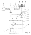
- the device is applied to a machine tool comprising at least one workpiece spindle 1 adapted to hold the workpiece 2.
- the workpiece 2 Before machining, the workpiece 2 is often in the form of a bar , pushed by a bar advancement device 3.
- the workpiece spindle 1 drives the workpiece 2 in rotation about its longitudinal axis, and can control the forward or backward movements of the workpiece 2 as illustrated by the arrow 4.
- Means are used to identify the position of spindle 1 during the machining cycle.
- a tool holder 5 is adapted to carry a tool 6 and to move it into the different machining positions desired during the machining cycle. Means make it possible to identify the position of the tool 6.
- Control means 7 are adapted to cause the movements of the functional members of the machine tool such as the workpiece spindle 1 and the tool holder 5 according to a succession of machining cycles.
- Each part execution cycle 2 includes one or more tool cycles starting at predetermined times during said part execution cycle.
- the tool holder 5 is mounted in displacement on traditional slides which are isolated from the frame 8 of the machine tool by insulating means 9.
- insulating means 9 can be interposed between the tool holder 5 and the tool 6. In all cases, the insulating means 9 electrically isolate the tool 6 relative to the frame 8 of the machine tool.
- the insulating means 9 comprise a layer of hard material and electrical insulator, to ensure both the electrical insulation of the tool 6 relative to the frame 8 and a rigid mechanical strength of the tool 6 to ensure good precision of machining.
- the hard and insulating material is a layer of polytetrafluoroethylene reinforced with glass fibers.
- the hard and insulating material is a layer of alumina.
- Electrical conductors 10 ensure the electrical connection of the tool 6 to the first output terminal 11 of an electrical voltage generator 12, the second terminal 13 of which is connected to the workpiece 2 during machining.
- the connection to the part 2 can pass through the workpiece pin 1, as illustrated in the figure, by the ground, or by a rotating contact or not with a specific conductor.
- a current sensor 14 is inserted in the electrical circuit formed by the conductors 10, and makes it possible to measure the electrical contact current in said conductors 10 and to produce on its output 15 a measurement signal sent to a comparator 17 which may be included in the control means 7.
- the invention provides a memory 16 for storing the limits of at least one control time range in the workpiece machining cycle, at the choice of the user.
- the invention further provides a threshold electrical signal generator 18, adapted to generate threshold electrical signals constituting admissible signal thresholds corresponding to an admissible range of contact current.
- the output of the threshold electrical signal generator 18 is connected to an input of the comparator 17, in order to send said threshold signals to the comparator 17.
- the threshold generator 18 can comprise the memory 16, in which a scale of contact current values is also recorded, comprising at least a threshold of admissible values I L from which the contact current I corresponds to a tool 6 having exceeded the admissible degree of wear to produce a correct part.
- the contact current is thus a physical parameter representative of the quality of the workpiece-tool contact.
- a simplified embodiment of the threshold generator can be a simple potentiometer, actuated by the user, and delivering a current or a fixed voltage chosen by the user to constitute a maximum or minimum threshold of admissible contact current values.
- the comparator 17 is adapted to scan the reception of the measurement signal at each time step of the control step defined in the memory 16, and to generate a fault signal in the event of the presence of a measurement signal whose value n ' is not admissible and indicates that the contact between the workpiece and the tool is not appropriate.
- the fault signal is used to warn the user and / or force the machining to stop or the tool to be changed.
- the current sensor 14 permanently provides a state of the contact current between the tool 6 and the part 2.
- This measurement of contact current also serves as a detection signal: in the absence of contact , the current measured is zero or very different from that which exists in the presence of contact, while in the presence of contact, the current takes a non-zero value.
- a zero or very different value of current detected by the current sensor 14 constitutes a detection signal.
- the comparator 17 can be adapted to compare, during each time range of control step, the measurement of contact electrical current received from the current sensor 14 and of the electrical contact current values recorded in the memory 16, and to generate a tool change signal when the measured contact current is not included in the admissible contact current values.
- the device shown in the figure performs a machining control comprising, for each part, at least one machining control step during which the workpiece spindle 1 and the tool holder 5 are in respective positions. predetermined machining, and during which the machining conditions are a priori the same for each part of a series of parts to be machined.
- this control step it is checked that an appropriate electric current, included in an admissible contact current range, crosses the contact zone between the tool 6 carried by the tool holder 5 and the part 2 held by the spindle workpiece carrier 1.
- the appropriateness or satisfaction of the electric current flowing through the contact zone between the tool and the workpiece is verified by measuring, at the predetermined machining instant, the electric current and by comparing it with the thresholds of admissible values.
- a fault signal is emitted which is later used in the machining cycle to generate the change of part or change of tool.
- FIG. 2 shows a possible variation of the electrical contact current I as a function of time during a tool cycle, that is to say during the machining of a part by a specific tool.
- a control step takes place during this tool cycle, and the value I 1 that the electric current I takes then is measured in the vicinity of this instant E.
- the invention makes it possible to eliminate the influence of numerous disturbing parameters capable of modifying the electric current I as a function of the machining conditions.
- the value I L limit of the admissible range of electrical contact current I is determined by a prior learning procedure, during which the first series of parts is machined with the same tool, checking a posteriori , using traditional verification instruments, the quality of the parts produced, the values of the electrical contact current I are measured and stored during the steps of controlling the machining cycles of said parts of the first series of parts, and said learning procedure is ceased upon obtaining a first defective part; the limit value I L of the admissible current range is chosen equal to the memorized value of the current I during the step of checking the last part preceding a defective part. I L is memorized automatically in the case of a programmed control device 7.
- control device 7 By programming the control device 7, a learning device making it possible to memorize in sequence the successive values of control time ranges and of associated admissible current ranges.
- a simplified control device 7 comprising for example a threshold generator 18 consisting of a simple potentiometer
- the user sets the potentiometer himself to the value producing on the comparator the control or alert as soon as it finds that the part produced is defective.
- a particular time range of the tool cycle, allowing very effective control, is the time range surrounding the cycle start time D as illustrated in FIG. 2.
- the electrical contact current I normally has a zero value, and, after this instant, the current I takes a value very different from the value 0.
- the appearance of an appropriate non-zero value of the current I during this first control time range gives several pieces of information: all d 'first, the part is probably well positioned on the workpiece spindle too, the tool probably has a correct geometry, indicating an acceptable degree of wear; also, the blank intended to form the part has a correct dimension, which will allow a correct part to be produced, and the blank is indeed in good place on the workpiece spindle.
- a fault appearing an appropriate value of current I during this first control time range indicates the presence of a fault, either in the workpiece or in the tool, and the detection of this fault.
- simultaneity allows an immediate command or warning signal to be sent, without continuing machining which would produce a defective part.
- the method according to the invention makes it possible to detect, at the start of the tool cycle, a tool defect or a material defect. It also allows, during each tool cycle or each part production cycle, to detect abnormal tool wear or tool breakage.
- the control is carried out during the same predetermined limited time periods of control as during the first series of parts.
- the user can advantageously refine the machining control by modifying, at the start of machining of the subsequent series of parts, at least one of the parameters consisting of the duration of the control time range and the extent of the admissible current range , to maximize the number of correct parts machined by the tool.
- a voltage generator 12 producing a modulated voltage, for example a direct voltage on which is superposed a modulation voltage whose waveform is determined.
- the measurement of the waveform of the current delivered in the contact between the part 2 and the tool 6 can give additional information on the quality of the machining obtained. This additional information can be used to generate a command or alert signal in the event that the machining becomes defective.
Abstract
Description
La présente invention concerne les machines-outils, dans lesquelles une pièce tenue par une broche porte-pièce et des outils tenus par un porte-outil sont déplacés les uns par rapport aux autres au cours d'un cycle d'usinage pour produire une pièce.The present invention relates to machine tools, in which a workpiece held by a workpiece spindle and tools held by a toolholder are moved relative to each other during a machining cycle to produce a workpiece .
L'invention se rapporte en particulier aux machines à décolleter telles que les tours monobroche à poupée fixe ou à poupée mobile, et les tours multibroche.The invention relates in particular to bar turning machines such as single spindle lathes with fixed headstock or movable headstock, and multispindle lathes.
La production de pièces dont les dimensions sont précises nécessite un contrôle efficace.The production of parts with precise dimensions requires effective control.
Le plus souvent, le contrôle est effectué a posteriori, en mesurant les dimensions de chaque pièce obtenue. Toutefois, un tel contrôle nécessite une reprise de la pièce, et il est effectué trop longtemps après la production de la pièce, de sorte que les pièces suivantes peuvent également être défectueuses lorsqu'on a constaté le défaut sur ladite pièce. Il en résulte une baisse de rendement et une baisse de qualité.Most often, the control is carried out a posteriori, by measuring the dimensions of each piece obtained. However, such a control requires a recovery of the part, and it is carried out too long after the production of the part, so that the following parts can also be defective when the defect has been found on said part. The result is a drop in yield and a drop in quality.
Il apparaît donc utile de prévoir un contrôle d'usinage qui s'effectue le plus tôt possible au cours de l'usinage de la pièce elle-même, sans toutefois ralentir cet usinage.It therefore seems useful to provide a machining control which is carried out as early as possible during the machining of the part itself, without however slowing down this machining.
Le document EP-A-0 363 902 décrit un dispositif et un procédé de contrôle d'usinage par la mesure et la vérification de la résistance électrique de contact entre l'outil et la pièce. Le document décrit les moyens pour mesurer avec une bonne précision la résistance électrique de contact, en éliminant l'effet perturbateur de la force électromotrice apparaissant dans la zone de contact qui se trouve à haute température pendant l'usinage. Pour cela, on fait passer un courant électrique intermittent dans la zone de contact entre la pièce et l'outil, et l'on mesure les différences de potentiel entre la pièce et l'outil. La résistance de contact est déduite par calcul, et est comparée à une série de valeurs de résistance de contact correspondant à la fois au type d'outil utilisé et aux matériaux formant la pièce à usiner.The document EP-A-0 363 902 describes a device and a method for controlling machining by measuring and checking the electrical resistance of contact between the tool and the part. The document describes the means for accurately measuring the electrical contact resistance, eliminating the disturbing effect of the electromotive force appearing in the contact zone which is at high temperature during machining. To do this, an intermittent electric current is passed through the contact area between the workpiece and the tool, and the potential differences between the workpiece and the tool are measured. The contact resistance is deduced by calculation, and is compared with a series of contact resistance values corresponding both to the type of tool used and to the materials forming the workpiece.
Outre sa relative complexité, puisqu'il faut prévoir des moyens pour générer un courant intermittent, des moyens pour mesurer une différence de potentiel à des instants différents, et des moyens pour calculer ensuite et comparer la résistance de contact, ce dispositif et ce procédé ne prennent pas en compte tous les paramètres pouvant perturber la mesure, notamment la présence d'huile de coupe conductrice ou isolante dans la zone de contact, la nature du matériau constituant la pièce à usiner, la nature du matériau constituant l'outil, la forme de l'outil et de la pièce, les paramètres d'usinage. Le procédé nécessite en outre d'utiliser des outils en des matériaux particuliers.Besides its relative complexity, since it is necessary to provide means for generating an intermittent current, means for measuring a potential difference at different times, and means for then calculating and comparing the contact resistance, this device and this process do not take into account all the parameters that can disturb the measurement, in particular the presence of conductive or insulating cutting oil in the contact area, the nature of the material constituting the workpiece, the nature of the material constituting the tool, the shape of the tool and the part, the machining parameters. The method also requires the use of tools made of particular materials.
Le document EP-A-0 165 745 enseigne de mesurer en permanence, pendant l'usinage, un paramètre tel qu'un courant de court-circuit, et de détecter l'augmentation rapide de la pente de ce paramètre indiquant l'imminence d'une rupture d'outil. Seule la rupture imminente d'outil est détectée par ce procédé. Cela ne permet pas de détecter les défauts qui, sans rupture d'outil, produisent des pièces néanmoins défectueuses.The document EP-A-0 165 745 teaches to continuously measure, during machining, a parameter such as a short-circuit current, and to detect the rapid increase in the slope of this parameter indicating the imminence of '' a tool break. Only the imminent tool breakage is detected by this process. This does not make it possible to detect faults which, without breaking the tool, produce nevertheless defective parts.
Le document US-A-3 728 621 enseigne de mesurer en permanence, pendant l'usinage, la tension de contact en présence d'un courant constant, et d'en déduire l'usure des arêtes de coupe de l'outil par comparaison avec un tableau de valeurs. Ce procédé ne donne toutefois qu'une valeur moyenne d'usure, et ne peut garantir la qualité des pièces produites. Il n'intègre pas, non plus, les nombreux paramètres pouvant perturber la mesure.Document US-A-3,728,621 teaches to continuously measure, during machining, the contact voltage in the presence of a constant current, and to deduce therefrom the wear of the cutting edges of the tool by comparison with an array of values. However, this process only gives an average wear value and cannot guarantee the quality of the parts produced. It also does not integrate the many parameters that can disturb the measurement.
Le document EP-A-0 509 817 décrit un système expert complexe et onéreux pour prédire la durée de vie d'un outil, par enregistrement de plusieurs séries de paramètres pendant plusieurs cycles d'usinage, et enregistrement de mesures de l'usure de l'outil. Cela ne permet pas de contrôler de façon fiable la qualité des pièces produites.Document EP-A-0 509 817 describes a complex and expensive expert system for predicting the life of a tool, by recording several series of parameters during several machining cycles, and recording measurements of wear of the tool. This does not allow reliable control of the quality of the parts produced.
Le problème proposé par la présente invention est de concevoir un nouveau procédé et un dispositif fiable et peu onéreux permettant le contrôle d'usinage de séries de pièces conductrices de l'électricité par un outil sur une machine-outil pendant ledit usinage, ce contrôle devant procurer des informations suffisantes pour connaître la qualité de la pièce qui sera obtenue, pour éviter la production d'une pièce défectueuse, et pour avertir l'utilisateur dès qu'une intervention est nécessaire.The problem proposed by the present invention is to design a new method and a reliable and inexpensive device allowing the control of machining of series of electrically conductive parts by a tool on a machine tool during said machining, this control having to provide sufficient information to know the quality of the part that will be obtained, to avoid the production of a defective part, and to warn the user as soon as an intervention is necessary.
Pour atteindre ces objets ainsi que d'autres, dans un procédé de contrôle d'usinage de séries de pièces conductrices de l'électricité par un outil sur une machine-outil, l'invention prévoit, au cours du cycle d'usinage de certaines au moins des pièces, au moins une étape de contrôle pendant au moins une plage temporelle limitée prédéterminée de contrôle, étape au cours de laquelle on connecte un générateur de tension électrique entre le porte-outil et la broche porte-pièce et on vérifie qu'un courant électrique de contact approprié, compris dans une plage admissible de courant de contact, traverse la zone de contact entre l'outil porté par le porte-outil et la pièce tenue par la broche porte-pièce, et on produit un signal de défaut en cas de détection d'un courant électrique de contact non approprié pendant ladite plage temporelle de contrôle.To achieve these and other objects, in a method of controlling the machining of series of electrically conductive parts by a tool on a machine tool, the invention provides, during the machining cycle of certain at least parts, at least one control step during at least a predetermined limited time period of control, step during which an electrical voltage generator is connected between the tool holder and the workpiece spindle and it is checked that an appropriate contact electrical current, included in an admissible range of contact current, passes through the contact zone between the tool carried by the tool holder and the part held by the workpiece spindle, and a fault signal is produced in the event of detection of an inappropriate contact electric current during said control time range.
Ainsi, l'idée qui est à la base de l'invention est d'effectuer un contrôle en associant la variable de temps et la variable de qualité du contact entre l'outil et la pièce. Le contrôle s'effectue ainsi de façon précise au voisinage d'instants bien définis dans le cycle d'usinage de chaque pièce, instants où la position du porte-outil, la position de la broche porte-pièce, et tous les autres paramètres qui déterminent en principe les conditions d'usinage doivent en principe se reproduire à l'identique d'une pièce à l'autre. Ces conditions d'usinage identiques déterminent la qualité du contact entre la pièce et l'outil, qualité que l'on détecte par mesure et comparaison du courant électrique traversant le contact, pour en déduire si l'usinage est normal ou non.Thus, the idea which is the basis of the invention is to carry out a control by associating the time variable and the quality variable of the contact between the tool and the part. The control is thus carried out precisely in the vicinity of well-defined times in the machining cycle of each part, times when the position of the tool holder, the position of the workpiece spindle, and all the other parameters which in principle determine the machining conditions must in principle be reproduced identically from one part to another. These identical machining conditions determine the quality of the contact between the part and the tool, quality which is detected by measurement and comparison of the electric current passing through the contact, to deduce therefrom whether the machining is normal or not.
On vérifie ainsi la qualité du contact mécanique entre pièce et outil en mesurant le courant électrique traversant la zone de contact et en le comparant à au moins une valeur de seuil admissible de ce courant électrique de contact. Par le fait que chaque étape de contrôle s'effectue pendant une plage temporelle limitée, très inférieure à la durée du cycle d'usinage, les conditions d'usinage sont particulières pendant cette plage temporelle, de sorte que la plage admissible de courant peut être considérablement réduite, permettant une détection fine de conditions d'usinage susceptibles de produire des pièces défectueuses.The quality of the mechanical contact between workpiece and tool is thus checked by measuring the electric current passing through the contact zone and by comparing it to at least one admissible threshold value of this electric contact current. By the fact that each control step is carried out during a limited time range, much less than the duration of the machining cycle, the machining conditions are particular during this time range, so that the admissible current range can be considerably reduced, allowing fine detection of machining conditions liable to produce defective parts.
Selon l'invention, on peut notamment prévoir, pour chaque pièce contrôlée, au moins une étape de contrôle de début d'usinage dans la plage temporelle au cours de laquelle le contact entre l'outil et la pièce doit s'établir, le courant électrique de contact étant estimé non approprié s'il n'a pas, au cours de la plage temporelle, une augmentation brusque d'amplitude appropriée indiquant l'établissement du contact.According to the invention, it is possible in particular to provide, for each part tested, at least one step for controlling the start of machining in the time range during which the contact between the tool and the part must be established, the current electric contact is considered inappropriate if it does not have, during the time range, a sudden increase in appropriate amplitude indicating the establishment of contact.
Egalement, on peut notamment prévoir, pour chaque pièce contrôlée, au moins une étape de contrôle en cours d'usinage dans une plage temporelle intermédiaire, le courant électrique de contact étant estimé non approprié s'il n'est pas compris dans une plage admissible respective de courant correspondant à ladite plage temporelle intermédiaire.Also, it is possible in particular to provide, for each part tested, at least one control step during machining in an intermediate time range, the electrical contact current being considered inappropriate if it is not included in an admissible range respective current corresponding to said intermediate time range.
Eventuellement, on peut prévoir, pour chaque pièce contrôlée, au moins une étape de contrôle de fin d'usinage dans la plage temporelle au cours de laquelle le contact entre l'outil et la pièce doit cesser, le courant électrique de contact étant estimé non approprié s'il n'a pas, au cours de la plage temporelle, une diminution brusque d'amplitude appropriée indiquant la fin du contact.Optionally, it is possible to provide, for each part tested, at least one step for controlling the end of machining in the time range during which the contact between the tool and the part must cease, the electric contact current being estimated not suitable if it does not have, during the time range, a sudden decrease of appropriate amplitude indicating the end of contact.
Selon un mode de réalisation particulier, permettant de simplifier sensiblement le dispositif, le procédé comprend une procédure préalable d'apprentissage au cours de laquelle on effectue l'usinage d'une première série de pièces avec un même outil, en vérifiant a posteriori, par exemple de façon connue, à l'aide d'instruments de vérification traditionnels ou non, la qualité des pièces réalisées ; on mesure et on mémorise les valeurs du courant électrique de contact traversant la zone de contact pièce-outil lors des étapes de contrôle des cycles d'usinage desdites pièces de la première série, et on cesse ladite procédure d'apprentissage à l'obtention d'une première pièce défectueuse et d'une mesure correspondante du courant électrique de contact, la valeur limite de la plage admissible de courant étant choisie égale au courant électrique de contact mesuré lors de l'usinage de la dernière pièce correcte de ladite première série de pièces.According to a particular embodiment, making it possible to simplify the device appreciably, the method comprises a prior learning procedure during which the first series of parts is machined with the same tool, by checking a posteriori, by example in a known manner, using traditional or non-traditional verification instruments, the quality of the parts produced; the values of the electrical contact current passing through the part-tool contact zone are measured and stored during the steps of controlling the machining cycles of said parts of the first series, and said learning procedure is stopped when obtaining '' a defective first part and a corresponding measurement of the electrical contact current, the limit value of the admissible current range being chosen equal to the electrical contact current measured during the machining of the last correct part of said first series of rooms.
Un dispositif de contrôle d'usinage de pièce sur machine-outil selon l'invention, mettant en oeuvre un tel procédé, est adapté à une machine-outil comprenant au moins une broche porte-pièce adaptée pour tenir la pièce à usiner, avec des moyens pour déplacer la broche et des moyens pour repérer la position de la broche, comprenant au moins un porte-outil avec des moyens pour déplacer l'outil et des moyens pour repérer la position de l'outil, et comprenant des moyens de commande pour provoquer les mouvements des organes fonctionnels de la machine-outil selon une succession de cycles d'usinage et pour repérer les étapes de cycle d'usinage. Selon l'invention, le dispositif comprend :
- des moyens isolants pour isoler électriquement l'outil ou le porte-outil par rapport au bâti de la machine-outil,
- des conducteurs électriques pour assurer la connexion électrique de l'outil à la première borne de sortie d'un générateur de tension électrique dont la seconde borne est connectée à ladite pièce en cours d'usinage,
- un capteur de courant, pour mesurer le courant électrique dans lesdits conducteurs, et pour produire sur sa sortie un signal de mesure envoyé à un comparateur,
- un générateur de signaux électriques de seuil, adapté pour générer des signaux électriques de seuil constituant des seuils de signaux admissibles correspondant à une plage admissible de courant de contact, et pour envoyer lesdits signaux de seuil au comparateur,
- une mémoire pour mémoriser les limites d'au moins une plage temporelle de contrôle dans le cycle d'usinage de pièce,
- le comparateur étant adapté pour scruter la réception d'un signal de mesure à chaque plage temporelle d'étape de contrôle définie par la mémoire, pour comparer ce signal de mesure auxdits signaux de seuil et pour générer un signal de défaut en cas de valeur non admissible dudit signal de mesure.
- insulating means for electrically insulating the tool or the tool holder with respect to the frame of the machine tool,
- electrical conductors to ensure the electrical connection of the tool to the first output terminal of a voltage generator electric, the second terminal of which is connected to said part during machining,
- a current sensor, for measuring the electric current in said conductors, and for producing on its output a measurement signal sent to a comparator,
- an electrical threshold signal generator, adapted to generate electrical threshold signals constituting admissible signal thresholds corresponding to an admissible range of contact current, and for sending said threshold signals to the comparator,
- a memory for storing the limits of at least one control time range in the workpiece machining cycle,
- the comparator being adapted to scan the reception of a measurement signal at each time step of the control step defined by the memory, to compare this measurement signal with said threshold signals and to generate a fault signal in the event of a value not permissible of said measurement signal.
D'autres objets, caractéristiques et avantages de la présente invention ressortiront de la description suivante d'un mode de réalisation particulier, faite en relation avec les figures jointes parmi lesquelles :
- la figure 1 représente schématiquement les organes essentiels d'un dispositif de contrôle d'usinage selon l'invention ;
- la figure 2 illustre schématiquement la forme d'onde du courant électrique traversant le contact outil-pièce pendant l'usinage d'une pièce ; et
- la figure 3 illustre schématiquement la forme d'onde du courant électrique traversant le contact outil-pièce pendant l'usinage d'une série de pièces avec un même outil.
- Figure 1 schematically shows the essential organs of a machining control device according to the invention;
- FIG. 2 schematically illustrates the waveform of the electric current passing through the tool-part contact during the machining of a part; and
- FIG. 3 schematically illustrates the waveform of the electric current passing through the tool-part contact during the machining of a series of parts with the same tool.
Comme illustré sur la figure 1, le dispositif est appliqué à une machine-outil comprenant au moins une broche porte-pièce 1 adaptée pour tenir la pièce à usiner 2. Avant usinage, la pièce à usiner 2 est souvent sous forme d'une barre, poussée par un dispositif d'avance de barre 3. La broche porte-pièce 1 entraîne la pièce 2 en rotation autour de son axe longitudinal, et peut commander les mouvements d'avance ou de recul de la pièce 2 comme illustré par la flèche 4. Des moyens permettent de repérer la position de la broche 1 au cours du cycle d'usinage.As illustrated in Figure 1, the device is applied to a machine tool comprising at least one
Un porte-outil 5 est adapté pour porter un outil 6 et pour le déplacer dans les différentes positions d'usinage désirées au cours du cycle d'usinage. Des moyens permettent de repérer la position de l'outil 6.A
Des moyens de commande 7 sont adaptés pour provoquer les mouvements des organes fonctionnels de la machine-outil tels que la broche porte-pièce 1 et le porte-outil 5 selon une succession de cycles d'usinage. Chaque cycle d'exécution de la pièce 2 comprend un ou plusieurs cycles d'outil commençant à des instants prédéterminés au cours dudit cycle d'exécution de pièce.Control means 7 are adapted to cause the movements of the functional members of the machine tool such as the
Dans le mode de réalisation illustré sur la figure 1, le porte-outil 5 est monté en déplacement sur des coulisses traditionnelles qui sont isolées du bâti 8 de la machine-outil par des moyens isolants 9. En alternative, des moyens isolants 9 peuvent être interposés entre le porte-outil 5 et l'outil 6. Dans tous les cas, les moyens isolants 9 isolent électriquement l'outil 6 par rapport au bâti 8 de la machine-outil.In the embodiment illustrated in FIG. 1, the
Les moyens isolants 9 comprennent une couche de matériau dur et isolant électrique, pour assurer à la fois l'isolation électrique de l'outil 6 par rapport au bâti 8 et une tenue mécanique rigide de l'outil 6 pour assurer une bonne précision d'usinage.The insulating means 9 comprise a layer of hard material and electrical insulator, to ensure both the electrical insulation of the
Selon un mode de réalisation, le matériau dur et isolant est une couche de polytétrafluoroéthylène armé de fibres de verre.According to one embodiment, the hard and insulating material is a layer of polytetrafluoroethylene reinforced with glass fibers.
Selon un autre mode de réalisation, le matériau dur et isolant est une couche d'alumine.According to another embodiment, the hard and insulating material is a layer of alumina.
Des conducteurs électriques 10 assurent la connexion électrique de l'outil 6 à la première borne de sortie 11 d'un générateur de tension électrique 12 dont la seconde borne 13 est connectée à la pièce à usiner 2 en cours d'usinage. La connexion à la pièce 2 peut passer par la broche porte-pièce 1, comme illustré sur la figure, par la masse, ou par un contact tournant ou non avec un conducteur spécifique.
Un capteur de courant 14 est inséré dans le circuit électrique formé par les conducteurs 10, et permet de mesurer le courant électrique de contact dans lesdits conducteurs 10 et de produire sur sa sortie 15 un signal de mesure envoyé à un comparateur 17 pouvant être compris dans les moyens de commande 7.A
L'invention prévoit une mémoire 16 pour mémoriser les limites d'au moins une plage temporelle de contrôle dans le cycle d'usinage de pièce, au choix de l'utilisateur.The invention provides a
L'invention prévoit en outre un générateur de signaux électriques de seuil 18, adapté pour générer des signaux électriques de seuil constituant des seuils de signaux admissibles correspondant à une plage admissible de courant de contact. La sortie du générateur de signaux électriques de seuil 18 est connectée à une entrée du comparateur 17, pour envoyer lesdits signaux de seuil au comparateur 17.The invention further provides a threshold
Par exemple, le générateur de seuil 18 peut comprendre la mémoire 16, dans laquelle est également enregistrée une échelle de valeurs de courant de contact, comportant au moins un seuil de valeurs admissibles IL à partir duquel le courant de contact I correspond à un outil 6 ayant dépassé le degré d'usure admissible pour réaliser une pièce correcte. Le courant de contact est ainsi un paramètre physique représentatif de la qualité du contact pièce-outil.For example, the
Un mode de réalisation simplifié du générateur de seuil peut être un simple potentiomètre, actionné par l'utilisateur, et délivrant un courant ou une tension fixe choisi par l'utilisateur pour constituer un seuil maximum ou minimum de valeurs admissibles de courant de contact.A simplified embodiment of the threshold generator can be a simple potentiometer, actuated by the user, and delivering a current or a fixed voltage chosen by the user to constitute a maximum or minimum threshold of admissible contact current values.
Le comparateur 17 est adapté pour scruter la réception du signal de mesure à chaque plage temporelle d'étape de contrôle définie dans la mémoire 16, et pour générer un signal de défaut en cas de présence d'un signal de mesure dont la valeur n'est pas admissible et indique que le contact entre la pièce et l'outil n'est pas approprié. Le signal de défaut est utilisé pour prévenir l'utilisateur et/ou forcer l'arrêt de l'usinage ou le changement d'outil.The
Selon un mode de réalisation préféré, le capteur de courant 14 fournit en permanence un état du courant de contact entre l'outil 6 et la pièce 2. Cette mesure de courant de contact sert également de signal de détection : en l'absence de contact, le courant mesuré est nul ou très différent de celui qui existe en présence de contact, tandis qu'en présence du contact, le courant prend une valeur non nulle. Une valeur nulle ou très différente de courant détectée par le capteur de courant 14 constitue un signal de détection.According to a preferred embodiment, the
Le comparateur 17 peut être adapté pour comparer, pendant chaque plage temporelle d'étape de contrôle, la mesure de courant électrique de contact reçue du capteur de courant 14 et des valeurs de courant électrique de contact enregistrées dans la mémoire 16, et pour générer un signal de changement d'outil lorsque le courant de contact mesuré n'est pas compris dans les valeurs admissibles de courant de contact.The
Ainsi, le dispositif représenté sur la figure effectue un contrôle d'usinage comportant, pour chaque pièce, au moins une étape de contrôle d'usinage au cours de laquelle la broche porte-pièce 1 et le porte-outil 5 sont dans des positions respectives prédéterminées d'usinage, et au cours de laquelle les conditions d'usinage sont a priori les mêmes pour chaque pièce d'une série de pièces à usiner. Pendant cette étape de contrôle, on vérifie qu'un courant électrique approprié, compris dans une plage admissible de courant de contact, traverse la zone de contact entre l'outil 6 porté par le porte-outil 5 et la pièce 2 tenue par la broche porte-pièce 1. Le caractère approprié ou satisfaisant du courant électrique traversant la zone de contact entre l'outil et la pièce est vérifié par la mesure, à l'instant prédéterminé d'usinage, du courant électrique et par sa comparaison aux seuils de valeurs admissibles.Thus, the device shown in the figure performs a machining control comprising, for each part, at least one machining control step during which the
En présence d'un courant électrique de contact non approprié pendant la plage déterminée de durée de vérification, un signal de défaut est émis qui est ultérieurement utilisé dans le cycle d'usinage pour générer le changement de pièce ou le changement d'outil.In the presence of an unsuitable contact electric current during the determined range of verification time, a fault signal is emitted which is later used in the machining cycle to generate the change of part or change of tool.
On a représenté sur la figure 2 une variation possible du courant électrique I de contact en fonction du temps lors d'un cycle d'outil, c'est-à-dire lors de l'usinage d'une pièce par un outil déterminé. Selon l'invention, une étape de contrôle intervient au cours de ce cycle d'outil, et on mesure alors la valeur I1 que prend le courant électrique I au voisinage de cet instant E. Par cette mesure au voisinage immédiat d'un instant précis, l'invention permet d'éliminer l'influence de nombreux paramètres perturbateurs susceptibles de modifier le courant électrique I en fonction des conditions d'usinage.FIG. 2 shows a possible variation of the electrical contact current I as a function of time during a tool cycle, that is to say during the machining of a part by a specific tool. According to the invention, a control step takes place during this tool cycle, and the value I 1 that the electric current I takes then is measured in the vicinity of this instant E. By this measurement in the immediate vicinity of an instant Precise, the invention makes it possible to eliminate the influence of numerous disturbing parameters capable of modifying the electric current I as a function of the machining conditions.
Comme illustré sur la figure 3, au cours de l'usinage d'une série de pièces identiques par le même outil, on peut avantageusement effectuer une étape de contrôle au cours de chaque cycle d'outil pour chaque cycle d'usinage de pièce. On constate que les valeurs de courant électrique de contact mesurées au cours des cycles successifs d'outil dérivent dans le temps en fonction notamment des conditions d'usure de l'outil. Au bout de N cycles d'outil, on atteint une valeur limite IL, qui précède juste l'instant à partir duquel la pièce suivante produite est défectueuse.As illustrated in FIG. 3, during the machining of a series of identical parts by the same tool, it is advantageously possible to carry out a control step during each tool cycle for each part machining cycle. It can be seen that the values of electrical contact current measured during successive tool cycles drift over time as a function in particular of the wear conditions of the tool. After N tool cycles, a limit value I L is reached, which just precedes the instant from which the next part produced is defective.
Ainsi, en comparant à chaque étape de contrôle la valeur I1 mesurée du courant électrique de contact I à la valeur IL limite ou aux seuils de valeurs admissibles, on peut en déduire si l'usinage est correct ou défectueux, et produire un signal de commande ou d'alerte lorsque l'usinage devient défectueux.Thus, by comparing at each control step the measured value I 1 of the electrical contact current I with the limit value I L or at the thresholds of admissible values, it can be deduced therefrom whether the machining is correct or defective, and produce a signal control or alert when the machining becomes defective.
La valeur IL limite de la plage admissible de courant électrique de contact I est déterminée par une procédure préalable d'apprentissage, au cours de laquelle on effectue l'usinage d'une première série de pièces avec un même outil, en vérifiant a posteriori, à l'aide d'instruments de vérification traditionnels, la qualité des pièces réalisées, on mesure et on mémorise les valeurs du courant électrique de contact I lors des étapes de contrôle des cycles d'usinage desdites pièces de la première série de pièces, et on cesse ladite procédure d'apprentissage à l'obtention d'une première pièce défectueuse ; la valeur limite IL de la plage admissible de courant est choisie égale à la valeur mémorisée du courant I lors de l'étape de contrôle de la dernière pièce précédant une pièce défectueuse. IL est mémorisée automatiquement dans le cas d'un dispositif de commande 7 programmé. On peut ainsi prévoir, par programmation du dispositif de commande 7, un dispositif d'apprentissage permettant de mémoriser en séquence les valeurs successives de plages temporelles de contrôle et de plages admissibles de courant associées. Dans le cas d'un dispositif de commande 7 simplifié, comportant par exemple un générateur de seuil 18 constitué d'un simple potentiomètre, l'utilisateur règle lui-même le potentiomètre à la valeur produisant sur le comparateur le signal de commande ou d'alerte dès qu'il constate que la pièce produite est défectueuse.The value I L limit of the admissible range of electrical contact current I is determined by a prior learning procedure, during which the first series of parts is machined with the same tool, checking a posteriori , using traditional verification instruments, the quality of the parts produced, the values of the electrical contact current I are measured and stored during the steps of controlling the machining cycles of said parts of the first series of parts, and said learning procedure is ceased upon obtaining a first defective part; the limit value I L of the admissible current range is chosen equal to the memorized value of the current I during the step of checking the last part preceding a defective part. I L is memorized automatically in the case of a programmed
Une plage temporelle particulière du cycle d'outil, permettant un contrôle très efficace, est la plage temporelle environnant l'instant de début de cycle D comme illustré sur la figure 2. Juste avant cet instant, le courant électrique de contact I a normalement une valeur nulle, et, après cet instant, le courant I prend une valeur très différente de la valeur 0. L'apparition d'une valeur appropriée non nulle du courant I au cours de cette première plage temporelle de contrôle donne plusieurs informations : tout d'abord, la pièce est vraisemblablement bien positionnée sur la broche porte-pièce également, l'outil a vraisemblablement une géométrie correcte, indiquant un degré d'usure admissible ; également, l'ébauche destinée à former la pièce a une dimension correcte, qui permettra de réaliser une pièce correcte, et l'ébauche est effectivement en bonne place sur la broche porte-pièce.A particular time range of the tool cycle, allowing very effective control, is the time range surrounding the cycle start time D as illustrated in FIG. 2. Just before this time, the electrical contact current I normally has a zero value, and, after this instant, the current I takes a value very different from the value 0. The appearance of an appropriate non-zero value of the current I during this first control time range gives several pieces of information: all d 'first, the part is probably well positioned on the workpiece spindle too, the tool probably has a correct geometry, indicating an acceptable degree of wear; also, the blank intended to form the part has a correct dimension, which will allow a correct part to be produced, and the blank is indeed in good place on the workpiece spindle.
Par contre, un défaut d'apparition d'une valeur appropriée de courant I au cours de cette première plage temporelle de contrôle indique la présence d'un défaut, soit dans la pièce, soit dans l'outil, et la détection de ce défaut de simultanéité permet d'émettre immédiatement un signal de commande ou d'avertissement, sans poursuivre l'usinage qui produirait une pièce défectueuse.On the other hand, a fault appearing an appropriate value of current I during this first control time range indicates the presence of a fault, either in the workpiece or in the tool, and the detection of this fault. simultaneity allows an immediate command or warning signal to be sent, without continuing machining which would produce a defective part.
Ainsi, le procédé selon l'invention permet de détecter, en début de cycle d'outil, un défaut d'outil ou un défaut de matière. Il permet également, au cours de chaque cycle d'outil ou de chaque cycle de réalisation de pièce, de détecter une usure anormale d'outil ou une cassure d'outil.Thus, the method according to the invention makes it possible to detect, at the start of the tool cycle, a tool defect or a material defect. It also allows, during each tool cycle or each part production cycle, to detect abnormal tool wear or tool breakage.
Au cours des étapes d'usinage des pièces des séries ultérieures, le contrôle s'effectue au cours des mêmes plages temporelles limitées prédéterminées de contrôle que lors de la première série de pièces. L'utilisateur peut avantageusement affiner le contrôle d'usinage en modifiant, en début d'usinage des séries ultérieures de pièces, l'un au moins des paramètres consistant dans la durée de plage temporelle de contrôle et l'étendue de plage admissible de courant, pour maximiser le nombre de pièces correctes usinées par l'outil.During the machining steps of the parts of the subsequent series, the control is carried out during the same predetermined limited time periods of control as during the first series of parts. The user can advantageously refine the machining control by modifying, at the start of machining of the subsequent series of parts, at least one of the parameters consisting of the duration of the control time range and the extent of the admissible current range , to maximize the number of correct parts machined by the tool.
Selon l'invention, il peut être avantageux d'utiliser un générateur de tension 12 produisant une tension modulée, par exemple une tension continue à laquelle est superposée une tension de modulation dont la forme d'onde est déterminée. La mesure de la forme d'onde du courant débité dans le contact entre la pièce 2 et l'outil 6 peut donner des informations supplémentaires sur la qualité de l'usinage obtenu. Ces informations supplémentaires peuvent servir pour générer un signal de commande ou d'alerte dans le cas où l'usinage deviendrait défectueux.According to the invention, it may be advantageous to use a
La présente invention n'est pas limitée aux modes de réalisation qui ont été explicitement décrits, mais elle en inclut les diverses variantes et généralisations contenues dans le domaine des revendications ci-après.The present invention is not limited to the embodiments which have been explicitly described, but it includes the various variants and generalizations thereof contained in the field of claims below.
Claims (10)
Applications Claiming Priority (2)
| Application Number | Priority Date | Filing Date | Title |
|---|---|---|---|
| FR9504699 | 1995-04-14 | ||
| FR9504699A FR2733064B1 (en) | 1995-04-14 | 1995-04-14 | METHOD AND DEVICE FOR MACHINE TOOL MACHINING CONTROL |
Publications (2)
| Publication Number | Publication Date |
|---|---|
| EP0737903A2 true EP0737903A2 (en) | 1996-10-16 |
| EP0737903A3 EP0737903A3 (en) | 1996-11-13 |
Family
ID=9478267
Family Applications (1)
| Application Number | Title | Priority Date | Filing Date |
|---|---|---|---|
| EP96420117A Withdrawn EP0737903A3 (en) | 1995-04-14 | 1996-04-10 | Method and device for monitoring machining on a machine-tool |
Country Status (2)
| Country | Link |
|---|---|
| EP (1) | EP0737903A3 (en) |
| FR (1) | FR2733064B1 (en) |
Cited By (5)
| Publication number | Priority date | Publication date | Assignee | Title |
|---|---|---|---|---|
| EP1197819A2 (en) * | 2000-10-11 | 2002-04-17 | Fuji Seiko Limited | Method and apparatus for controlling movement of cutting blade and workpiece |
| FR2934801A1 (en) * | 2008-08-06 | 2010-02-12 | Forest Line Albert | METHOD AND APPARATUS FOR ACCURATE ACCOMMODATION OF A WORKPIECE USED BY A ROTATING TOOL |
| EP2159654A1 (en) * | 2008-08-27 | 2010-03-03 | Kawasaki Jukogyo Kabushiki Kaisha | Automatic finishing machine and control method thereof |
| US20170282320A1 (en) * | 2014-09-18 | 2017-10-05 | Korea Institute Of Industrial Technology | Module for detecting contact between object to be processed and precision tool tip and method for detecting contact using same |
| WO2018206455A1 (en) * | 2017-05-11 | 2018-11-15 | Walter Maschinenbau Gmbh | Grinding and/or eroding machine, and method for measuring and/or referencing the machine |
Citations (5)
| Publication number | Priority date | Publication date | Assignee | Title |
|---|---|---|---|---|
| US3728621A (en) * | 1967-11-27 | 1973-04-17 | Smith E Frost | Apparatus for measuring the wear of cutting edges of cutting tools |
| EP0165745A2 (en) * | 1984-06-18 | 1985-12-27 | Borg-Warner Corporation | Cutting tool wear monitor |
| FR2577456A1 (en) * | 1985-02-18 | 1986-08-22 | Yvorra Henri | DEVICE FOR THE RELATIVE POSITIONING OF A TOOL AND WORKPIECE |
| EP0363902A2 (en) * | 1988-10-14 | 1990-04-18 | Sumitomo Electric Industries, Ltd. | Method of detecting wear of cutting tool |
| EP0509817A1 (en) * | 1991-04-18 | 1992-10-21 | Texas Instruments Incorporated | System and method utilizing a real time expert system for tool life prediction and tool wear diagnosis |
Family Cites Families (3)
| Publication number | Priority date | Publication date | Assignee | Title |
|---|---|---|---|---|
| JPS608178B2 (en) * | 1978-06-29 | 1985-03-01 | 豊田工機株式会社 | Contact detection device |
| JPS5548557A (en) * | 1978-09-27 | 1980-04-07 | Toyoda Mach Works Ltd | Numerically controlled machine tool with dimensional precision approval function |
| JPS5615952A (en) * | 1979-07-18 | 1981-02-16 | Toyoda Mach Works Ltd | Contact detector |
-
1995
- 1995-04-14 FR FR9504699A patent/FR2733064B1/en not_active Expired - Fee Related
-
1996
- 1996-04-10 EP EP96420117A patent/EP0737903A3/en not_active Withdrawn
Patent Citations (5)
| Publication number | Priority date | Publication date | Assignee | Title |
|---|---|---|---|---|
| US3728621A (en) * | 1967-11-27 | 1973-04-17 | Smith E Frost | Apparatus for measuring the wear of cutting edges of cutting tools |
| EP0165745A2 (en) * | 1984-06-18 | 1985-12-27 | Borg-Warner Corporation | Cutting tool wear monitor |
| FR2577456A1 (en) * | 1985-02-18 | 1986-08-22 | Yvorra Henri | DEVICE FOR THE RELATIVE POSITIONING OF A TOOL AND WORKPIECE |
| EP0363902A2 (en) * | 1988-10-14 | 1990-04-18 | Sumitomo Electric Industries, Ltd. | Method of detecting wear of cutting tool |
| EP0509817A1 (en) * | 1991-04-18 | 1992-10-21 | Texas Instruments Incorporated | System and method utilizing a real time expert system for tool life prediction and tool wear diagnosis |
Non-Patent Citations (3)
| Title |
|---|
| PATENT ABSTRACTS OF JAPAN vol. 004, no. 037 (M-004), 27 Mars 1980 & JP 55 011706 A (TOYODA MACH WORKS LTD), 26 Janvier 1980, * |
| PATENT ABSTRACTS OF JAPAN vol. 004, no. 092 (M-018), 3 Juillet 1980 & JP 55 048557 A (TOYODA MACH WORKS LTD), 7 Avril 1980, * |
| PATENT ABSTRACTS OF JAPAN vol. 005, no. 065 (M-066), 30 Avril 1981 & JP 56 015952 A (TOYODA MACH WORKS LTD), 16 Février 1981, * |
Cited By (11)
| Publication number | Priority date | Publication date | Assignee | Title |
|---|---|---|---|---|
| EP1197819A2 (en) * | 2000-10-11 | 2002-04-17 | Fuji Seiko Limited | Method and apparatus for controlling movement of cutting blade and workpiece |
| US6758640B2 (en) * | 2000-10-11 | 2004-07-06 | Fuji Seiko Limited | Method and apparatus for controlling movement of cutting blade and workpiece |
| EP1197819A3 (en) * | 2000-10-11 | 2005-01-26 | Fuji Seiko Limited | Method and apparatus for controlling movement of cutting blade and workpiece |
| US7056072B2 (en) | 2000-10-11 | 2006-06-06 | Fuji Seiko Limited | Method and apparatus for controlling movement of cutting blade and workpiece |
| FR2934801A1 (en) * | 2008-08-06 | 2010-02-12 | Forest Line Albert | METHOD AND APPARATUS FOR ACCURATE ACCOMMODATION OF A WORKPIECE USED BY A ROTATING TOOL |
| EP2159654A1 (en) * | 2008-08-27 | 2010-03-03 | Kawasaki Jukogyo Kabushiki Kaisha | Automatic finishing machine and control method thereof |
| US8229594B2 (en) | 2008-08-27 | 2012-07-24 | Kawasaki Jukogyo Kabushiki Kaisha | Automatic finishing machine and control method thereof |
| US20170282320A1 (en) * | 2014-09-18 | 2017-10-05 | Korea Institute Of Industrial Technology | Module for detecting contact between object to be processed and precision tool tip and method for detecting contact using same |
| WO2018206455A1 (en) * | 2017-05-11 | 2018-11-15 | Walter Maschinenbau Gmbh | Grinding and/or eroding machine, and method for measuring and/or referencing the machine |
| KR20200004396A (en) * | 2017-05-11 | 2020-01-13 | 발테르 마쉬넨바우 게엠베하 | Grinding and / or erosion machines, and methods for measuring and reference thereof |
| AU2018265182B2 (en) * | 2017-05-11 | 2023-11-02 | Walter Maschinenbau Gmbh | Grinding and/or Erosion Machine, as well as Method for Gauging and/or Referencing of the Machine |
Also Published As
| Publication number | Publication date |
|---|---|
| EP0737903A3 (en) | 1996-11-13 |
| FR2733064B1 (en) | 1997-05-30 |
| FR2733064A1 (en) | 1996-10-18 |
Similar Documents
| Publication | Publication Date | Title |
|---|---|---|
| EP0695414A1 (en) | Method for measuring the thickness of a transparent material | |
| FR2583329A1 (en) | ACOUSTIC DETECTOR FOR BREAKING AND TOOL FLASHING AND METHOD OF OPTIMIZING THE SAME | |
| EP0210689A1 (en) | Apparatus for a rapid determination of the rheological properties of thermoplastic materials | |
| FR2505040A1 (en) | APPARATUS FOR DETECTING THE POSITION OF A PROBE IN RELATION TO A PIECE | |
| CA2659840C (en) | Method of aligning an axisymmetric vibrating sensor inertial navigation system and corresponding inertial navigation system | |
| FR2569879A1 (en) | CONTROL DEVICE AND METHOD FOR ACOUSTICALLY DETECTING A CONTACT BETWEEN A CUTTING TOOL AND A WORKPIECE | |
| WO2006003347A1 (en) | Method for monitoring a resistance welding process and device therefor | |
| FR2461549A1 (en) | EROSIVE SPARKING MACHINING METHOD AND DEVICE | |
| FR2533705A1 (en) | ION CONCENTRATION DETECTOR IN A LIQUID | |
| EP0737903A2 (en) | Method and device for monitoring machining on a machine-tool | |
| EP0077243A1 (en) | Method to record data representative of the form of an object | |
| EP3384592B1 (en) | Method and device for detecting an electric arc in a photovoltaic installation | |
| EP0064454B1 (en) | Method to position a member laterally with respect to a joint formed between two metallic surfaces, and showing discontinuities | |
| EP0080406B1 (en) | Method and apparatus for interrogating a combustible gas concentration sensor | |
| EP1008415B1 (en) | Cutting device for metallic workpieces comprising a cutting gun and a capacitive sensor | |
| FR2733707A1 (en) | METHOD AND DEVICE FOR CHECKING AND ADJUSTING THE POSITION OF THE FIREPLACE DURING THE MACHINING OF A LASER MATERIAL | |
| FR2614223A1 (en) | SPINNING MACHINING DEVICE CONTROLLING THE PRECISION OF MACHINING. | |
| EP0257164B1 (en) | Device for relative positioning between a tool and a work piece | |
| EP1131599B1 (en) | Device for measuring the dimension and controlling of defects in optical fibres during production | |
| FR2667977A1 (en) | METHOD AND MACHINE FOR MARKING ELECTRICAL CABLE | |
| EP0125171B1 (en) | Method and device for the determination by optical emission spectrometry of an element such as aluminium present in a dissolved and precipitated state in a metal such as steel | |
| EP3736066B1 (en) | System and method for resizing the rolling surface of a wheel | |
| EP3615906A1 (en) | Method for detecting a state or a malfunction by vibratory analysis | |
| EP1118418B1 (en) | Resistance welding monitoring method | |
| EP0128824A1 (en) | Process and device for monitoring the position of a slide in the interior of a thick-walled casing |
Legal Events
| Date | Code | Title | Description |
|---|---|---|---|
| PUAI | Public reference made under article 153(3) epc to a published international application that has entered the european phase |
Free format text: ORIGINAL CODE: 0009012 |
|
| PUAL | Search report despatched |
Free format text: ORIGINAL CODE: 0009013 |
|
| AK | Designated contracting states |
Kind code of ref document: A2 Designated state(s): CH DE FR GB LI |
|
| AK | Designated contracting states |
Kind code of ref document: A3 Designated state(s): CH DE FR GB LI |
|
| 17P | Request for examination filed |
Effective date: 19970321 |
|
| 17Q | First examination report despatched |
Effective date: 19990305 |
|
| STAA | Information on the status of an ep patent application or granted ep patent |
Free format text: STATUS: THE APPLICATION IS DEEMED TO BE WITHDRAWN |
|
| 18D | Application deemed to be withdrawn |
Effective date: 19990716 |