EP0737814A1 - Compressor - Google Patents
Compressor Download PDFInfo
- Publication number
- EP0737814A1 EP0737814A1 EP96810177A EP96810177A EP0737814A1 EP 0737814 A1 EP0737814 A1 EP 0737814A1 EP 96810177 A EP96810177 A EP 96810177A EP 96810177 A EP96810177 A EP 96810177A EP 0737814 A1 EP0737814 A1 EP 0737814A1
- Authority
- EP
- European Patent Office
- Prior art keywords
- hub
- blades
- compressor
- compressor according
- reinforced
- Prior art date
- Legal status (The legal status is an assumption and is not a legal conclusion. Google has not performed a legal analysis and makes no representation as to the accuracy of the status listed.)
- Granted
Links
Images


Classifications
-
- F—MECHANICAL ENGINEERING; LIGHTING; HEATING; WEAPONS; BLASTING
- F04—POSITIVE - DISPLACEMENT MACHINES FOR LIQUIDS; PUMPS FOR LIQUIDS OR ELASTIC FLUIDS
- F04D—NON-POSITIVE-DISPLACEMENT PUMPS
- F04D29/00—Details, component parts, or accessories
- F04D29/26—Rotors specially for elastic fluids
- F04D29/32—Rotors specially for elastic fluids for axial flow pumps
- F04D29/38—Blades
-
- F—MECHANICAL ENGINEERING; LIGHTING; HEATING; WEAPONS; BLASTING
- F04—POSITIVE - DISPLACEMENT MACHINES FOR LIQUIDS; PUMPS FOR LIQUIDS OR ELASTIC FLUIDS
- F04D—NON-POSITIVE-DISPLACEMENT PUMPS
- F04D29/00—Details, component parts, or accessories
- F04D29/02—Selection of particular materials
- F04D29/023—Selection of particular materials especially adapted for elastic fluid pumps
-
- F—MECHANICAL ENGINEERING; LIGHTING; HEATING; WEAPONS; BLASTING
- F04—POSITIVE - DISPLACEMENT MACHINES FOR LIQUIDS; PUMPS FOR LIQUIDS OR ELASTIC FLUIDS
- F04D—NON-POSITIVE-DISPLACEMENT PUMPS
- F04D29/00—Details, component parts, or accessories
- F04D29/26—Rotors specially for elastic fluids
- F04D29/28—Rotors specially for elastic fluids for centrifugal or helico-centrifugal pumps for radial-flow or helico-centrifugal pumps
- F04D29/284—Rotors specially for elastic fluids for centrifugal or helico-centrifugal pumps for radial-flow or helico-centrifugal pumps for compressors
-
- F—MECHANICAL ENGINEERING; LIGHTING; HEATING; WEAPONS; BLASTING
- F05—INDEXING SCHEMES RELATING TO ENGINES OR PUMPS IN VARIOUS SUBCLASSES OF CLASSES F01-F04
- F05D—INDEXING SCHEME FOR ASPECTS RELATING TO NON-POSITIVE-DISPLACEMENT MACHINES OR ENGINES, GAS-TURBINES OR JET-PROPULSION PLANTS
- F05D2300/00—Materials; Properties thereof
- F05D2300/40—Organic materials
- F05D2300/43—Synthetic polymers, e.g. plastics; Rubber
-
- F—MECHANICAL ENGINEERING; LIGHTING; HEATING; WEAPONS; BLASTING
- F05—INDEXING SCHEMES RELATING TO ENGINES OR PUMPS IN VARIOUS SUBCLASSES OF CLASSES F01-F04
- F05D—INDEXING SCHEME FOR ASPECTS RELATING TO NON-POSITIVE-DISPLACEMENT MACHINES OR ENGINES, GAS-TURBINES OR JET-PROPULSION PLANTS
- F05D2300/00—Materials; Properties thereof
- F05D2300/60—Properties or characteristics given to material by treatment or manufacturing
- F05D2300/603—Composites; e.g. fibre-reinforced
Definitions
- the invention is based on a compressor for gaseous fluids according to the preamble of claim 1.
- a compressor is known from the document EP 0 593 797 A1, which is provided for the compression of a gaseous medium.
- the compressor has a compressor wheel with molded rotor blades which are provided with a casing on the side on which the gaseous medium enters.
- the shroud is connected to the ends of all the blades.
- the casing does not extend over the entire length of the blades. In the area in which the rotor blades are subjected to the highest mechanical stress, no casing is provided which could prevent the same from vibrating or at least dampen it somewhat.
- a compressor wheel for a compressor which is made of a metal, the blades of which are integrally formed on the hub of the compressor wheel.
- Such a compressor wheel is usually machined from the solid with the help of complex machining processes.
- This The compressor wheel has a comparatively large mass, for the drive of which a comparatively large amount of energy has to be expended.
- Compressors are also known which have compressor wheels molded in one piece from plastic. Some of these compressor wheels are provided with fiber reinforcement, but the manufacturing processes used to date only allow reinforcement with so-called short fibers. Compressor wheels designed in this way can only be used for peripheral speeds up to a maximum of 400 m / sec and for operating temperatures up to a maximum of 200 ° C, since the reinforcement with short fibers does not allow higher loads.
- the invention solves the problem of creating a compressor which has a compressor wheel made of a plastic and which is nevertheless suitable for comparatively high operating temperatures.
- the compressor wheel has a lower mass and it is comparatively easy to assemble from different individual parts.
- the A pre-made, carbon fiber reinforced thermoplastic tape is used. With this thermoplastic tape, the orientation of the continuous fibers reinforcing it is always optimally guaranteed, so that a comparatively good strength of the hub is ensured even at these comparatively high operating temperatures and peripheral speeds. Thanks to the comparatively low mass of the compressor wheel, it also has a small moment of inertia, so that the compressor reaches the required operating speed in an advantageously short time when starting and is therefore fully effective very quickly.
- the compressor wheel 1 shows a schematically illustrated partial section through a compressor wheel 1, which is provided for the compression of a gaseous fluid.
- the compressor wheel 1 has a hub 2 which is made of a plastic, preferably of a thermoplastic material reinforced with continuous fibers.
- the hub 2 is fastened on a sleeve 3 made of metal, and is secured against rotation and against axial slipping.
- the hub 2 and the sleeve 3 have a common axis 4, which represents the axis of rotation of the compressor wheel 1.
- the sleeve 3 has a central bore which is provided for receiving and fastening the shaft of the compressor wheel 1, not shown.
- rotor blades 5 are fastened. Between the blades 5 and the compressor housing 1, not shown, including the compressor wheel 1, there are flow channels (not designated) into which the gaseous medium flows and in which it is accelerated in a known manner and thereby compressed.
- the hub 2 was wound from a prefabricated plastic tape reinforced with continuous fibers.
- plastic tape reinforced with continuous fibers.
- particularly temperature-resistant thermoplastics are suitable as plastic, and carbon fibers are used for the reinforcement.
- the hub 2 was wound on a gauge corresponding to the inner contour of the hub 2 in such a way that the carbon fibers are arranged in the circumferential direction, which results in a particularly high strength of the hub 2 in this direction, as a result of which comparatively high speeds of the compressor wheel 1 and thus comparatively large Efficiency of the compressor become possible.
- the thermoplastic material of the tape was briefly heated and fused to the previously applied layer of the tape.
- a laser is particularly suitable for this targeted and dosed short-term heating.
- Such thermoplastic winding processes using lasers as an energy source are known. After the winding process was completed, the hub 2 thus prefabricated was removed from the gauge and definitely finished.
- the opening for receiving the sleeve 3 had to be reworked and, in addition, the outer surface of the hub 2 had to be smoothed in order to be able to use it as a support and adhesive surface for fastening the prefabricated rotor blades 5.
- the blades 5 each have an aerodynamically designed inlet edge 6, which lies on the inlet side of the gaseous medium in the flow channel of the compressor. On the other side of the flow channel, based on the flow of the gaseous medium downstream, is the exit edge 7 of the rotor blades 5.
- the rotor blades 5 are assembled from several prefabricated parts, also reinforced with continuous fibers, as schematically shown in FIGS. 4 and 5 is shown. These figures are discussed below.
- the blades 5 each have a base plate 8 as the base.
- the side of the foot plate 8 facing the surface 9 of the hub 2 is adapted to this surface 9 so precisely that this foot plate 8 lies positively on the surface 9.
- the surface 9 has a shoulder 10 on the inlet side of the compressor wheel 1, on which the inlet-side end piece 11 of the base plate 8 also rests in a form-fitting manner.
- the rotor blades 5 are designed to be aerodynamically known in a known manner; the corresponding spherical curvature of the airfoil is not shown in the drawing for the sake of clarity.
- the base of the rotor blades 5 forms the preformed, uniformly thick base plate 8.
- the base plate 8 is provided with a bead 26 which projects into the interior of the rotor blade 5 and which extends in the direction of the longitudinal axis of the rotor blade 5, with it becoming less pronounced downstream is.
- the base plate 8 has an underside 27 which is completely aligned with the surface 9 of the hub 2.
- the depression occurring in the underside 27 as a result of the bulge 26 is filled up by means of an epoxy resin filling 28 in such a way that in this area of the base plate 8 there is also a surface which is completely aligned with the surface 9 of the hub 2.
- the bead 26 is provided with evenly rounded flanks.
- the airfoil is formed by two side walls 29 and 30.
- the side walls 29 and 30 are made of uniformly thick plastic plates reinforced with continuous fibers, they enclose a cavity 31 that becomes narrower in the radial direction. This cavity 31 can be foamed in order to achieve better vibration damping.
- the cavity 31 is closed in the area of the leading edge 6 of the rotor blade 5 by means of a cover, not shown, which is designed to be aerodynamic.
- the side walls 29 and 30 are preformed. They are glued or welded to the base plate 8 in an assembly template. At the same time, the side walls 29 and 30 glued or welded together in the area of the tip of the blades 5.
- the side walls 29 and 30 are designed in such a way that they each have a foot part 32a, 32b which fits the surface of the footplate 8 in a form-fitting manner and which has a radius 33 which merges with the approximately radially extending part of the respective side wall.
- the foot part 32a is assigned to the side wall 29 and the foot part 32b to the side wall 30. End pieces are formed on the upstream side of the foot parts 32a and 32b, which fit the end piece 11 of the foot plate 8 and rest positively on the surface of the foot plate 8.
- the radius 33 is precisely adapted to the radius of the flank of the bead 26.
- FIG. 5 shows a partial section through a second embodiment of a rotor blade 5 of a compressor wheel 1.
- This embodiment differs from the embodiment according to FIG. 4 in that the approximately radially extending part of the side walls 29 and 30 is somewhat bulged.
- This design ensures that the stresses between the base parts 32a and 32b of the side walls 29 and 30 and the base plate 8 are significantly reduced when the rotor blades 5 are mechanically loaded, the rotor blades 5 thus formed are therefore particularly resistant to high centrifugal forces.
- a compressor wheel 1 equipped with rotor blades 5 designed in this way is suitable for particularly high peripheral speeds.
- the hub 2 On the outlet side, the hub 2 has a collar 12, against which the outlet-side end 13 of the rotor blade 5 abuts.
- the end 13 is formed from the footplate 8 covered with the foot parts 32a and 32b.
- the collar 12 is on this point is the same width as the thickness of this outlet-side end 13 of the rotor blade 5, so that no protruding edge interferes with the flow of the compressed medium flowing out of the compressor wheel 1.
- the underside of the base plate 8 is glued or welded to the surface 9 of the hub 2.
- the base plates 8 are covered with the base parts 32a and 32b in such a way that the entire surface 9 is covered in the finished compressor wheel 1.
- a bandage 14 is additionally attached to the entry side after the adhesive has been bonded and after the adhesive has hardened, so that the end piece 11 of each footplate 8 together with the end pieces of the foot parts 32a and 32b against the shoulder 10 of the hub 2 is pressed.
- the bandage 14 is wound from a prefabricated plastic band reinforced with continuous fibers.
- particularly temperature-resistant thermoplastics reinforced with carbon fibers are suitable as plastics.
- the bandage 14 was wound in such a way that the carbon fibers lie in the circumferential direction, which results in a particularly high strength of the bandage 14 in this direction, as a result of which the base plates 8 and the base parts 32a and 32b are held securely even at comparatively high speeds of the compressor wheel 1 .
- the thermoplastic material of the tape is briefly heated and fused to the previously applied layer of the tape.
- the bandage 14 is accordingly manufactured using the same method as the hub 2. After the winding, the surface 15 of the bandage 14 is reworked in order to achieve a streamlined shape of the bandage 14.
- the moving blades 5 are held by the gluing or welding, the bandage 14 and the collar 12. Up to comparatively high speeds of the compressor wheel 1, this fastening is sufficient. However, even higher speeds required, the blades 5 are additionally riveted to the hub 2 by means of metal rivets, namely the base parts 32a and 32b are riveted together with the base plates 8 to the hub 2. When riveting, care is taken that the rivet heads do not disturb the flow of the medium in the flow channels, since this would result in a loss of efficiency.
- FIG. 2 shows a schematically represented partial section through the compressor wheel according to FIG. 1, specifically showing section A-A.
- the blades 5, which are assembled from several components, have bevels 16a, 16b in the edge region where they touch the adjacent blades 5, which allow the edges of the blades 5 to be pushed over one another and to be glued effectively, as a result of which a closed surface 17 of the axis 4 facing side of the flow channel 18 is reached.
- the dashed line 19 indicates the compressor housing, which closes the flow channel 18, which is laterally delimited by the rotor blades 5, to the outside.
- FIG. 3 shows a partial section through a second embodiment of a compressor wheel.
- This embodiment differs from that according to FIG. 1 in that in the space between two rotor blades 5 there is in each case a further rotor blade 20 which has an inlet edge 21 which is arranged downstream of the inlet edge 6 of the rotor blades 5. Each flow channel is divided downstream into two flow channels by the blade 20.
- the rotor blade 20 has an outlet edge which is arranged in the same plane as the outlet edge 7 of the rotor blades 5.
- the blades 20 are designed in accordance with the blades 5.
- the blades 20 are also provided with a base plate to which the corresponding base parts have been applied.
- the connected foot parts fit precisely into recesses in the foot parts 32 a and 32 b of the rotor blades 5, the rotor blades 20 each being positively pushed under the rotor blades 5.
- the blades 5 hold the blades 20 in addition to their gluing or welding by means of dovetail teeth.
- the rotor blades 20 are accordingly fastened to the hub 2 in a manner similar to the rotor blades 5.
- the end piece 22 lies positively on a shoulder 23 of the hub 2.
- a bandage 24 is attached in addition to the bandage 14 such that the end pieces 22 of each of the blades 5 and each the blades 20 together with the end pieces of the respective foot parts are pressed against the shoulder 23 of the hub 2.
- the bandage 24, like the bandage 14, is wound from a prefabricated plastic band reinforced with continuous fibers and welded accordingly. The surface of the bandage 24 is then also designed to be streamlined.
- the compressor wheel 1 according to FIG. 3 also has a balancing ring 25 which was inserted into the hub 2 during winding.
- the balancing ring 25 is made of metal.
- material is removed from this balancing ring in order to eliminate existing imbalances. It is also possible to design the sleeve 3 with a larger mass and to carry out the necessary material removal on it, so that the balancing ring 25 can be saved.
- an adhesive based on a phenolic resin is provided, here the adhesive HT 424 the American Cyanamid Company, 1300 Revolution Street, Havre de Grace, MD 21087, has proven particularly suitable. Furthermore, the adhesive based on a modified condensation polyimide from the same manufacturer with the designation FM 36 is also well suited for the joining described here. In addition to gluing, a welding process using a laser or a combination of both methods is also conceivable for connecting the parts of the rotor blades 5. The blades 20 are assembled in the same way.
- the band for the production of the hub 2 and the bandages 14 and 24 has a matrix made of a thermoplastic.
- polyphenylene sulfide has proven itself as a thermoplastic, and good results have also been achieved with polyether ether ketone.
- the polyphenylene sulfide matrix was reinforced with a carbon fiber volume content of about 53%.
- the cross section of this tape was 5mm x 0.158mm.
- the elastic modulus of the tape was found to be 114 GPa.
- the operating temperature in this case was around 220 ° C.
- the matrix made of polyether ether ketone was reinforced with a volume content of carbon fibers of 61%.
- the cross section of this tape was 5mm x 0.125mm.
- the elastic modulus of the tape was 134,000 MPa.
- the operating temperature in this case was around 280 ° C.
- thermoplastic plastic is used as the material for the production of the components of the rotor blades 5, 20, which is reinforced with carbon fibers designed as continuous fibers. This material is in shape delivered from uniformly thick panels. A matrix of polyether ether ketone with a volume content of carbon fibers of 61% has proven to be particularly suitable. These plates are inserted into molds and are brought into their final shape under thermal stress using one of the known methods, taking care that the continuous fibers are oriented in the direction of the main dynamic stress on the rotor blades 5, 20. The components prefabricated in this way, the side walls 29 and 30 and the base plate 8, of the moving blades 5, 20 are then, as already described, assembled in an assembly template to the finished moving blade 5 or 20.
Landscapes
- Engineering & Computer Science (AREA)
- Mechanical Engineering (AREA)
- General Engineering & Computer Science (AREA)
- Structures Of Non-Positive Displacement Pumps (AREA)
Abstract
Description
Die Erfindung geht aus von einem Verdichter für gasförmige Fluide gemäss dem Oberbegriff des Anspruchs 1.The invention is based on a compressor for gaseous fluids according to the preamble of
Aus der Schrift EP 0 593 797 A1 ist ein Verdichter bekannt, der für die Verdichtung eines gasförmigen Mediums vorgesehen ist. Der Verdichter weist ein Verdichterrad auf mit angeformten Laufschaufeln, die auf der Seite, auf der das gasförmige Medium eintritt, mit einer Ummantelung versehen sind. Die Ummantelung ist mit den Enden aller Laufschaufeln verbunden. Die Ummantelung erstreckt sich nicht über die gesamte Länge der Laufschaufeln. In dem Bereich, in dem die Laufschaufeln mechanisch am höchsten belastet sind, ist keine Ummantelung vorgesehen, welche Vibrationen derselben verhindern oder zumindest etwas abdämpfen könnte.A compressor is known from the document EP 0 593 797 A1, which is provided for the compression of a gaseous medium. The compressor has a compressor wheel with molded rotor blades which are provided with a casing on the side on which the gaseous medium enters. The shroud is connected to the ends of all the blades. The casing does not extend over the entire length of the blades. In the area in which the rotor blades are subjected to the highest mechanical stress, no casing is provided which could prevent the same from vibrating or at least dampen it somewhat.
Aus der Patentschrift CH 675 279 ist ein Verdichterrad für einen Verdichter bekannt, welches aus einem Metall gefertigt ist, wobei dessen Laufschaufeln einstückig an die Nabe des Verdichterrads angeformt sind. Ein derartiges Verdichterrad wird in der Regel aus dem Vollen herausgearbeitet mit Hilfe von aufwendigen spanabhebenden Verfahren. Dieses Verdichterrad weist eine vergleichsweise grosse Masse auf, für deren Antrieb eine vergleichsweise grosse Energie aufgewendet werden muss.From the patent specification CH 675 279 a compressor wheel for a compressor is known, which is made of a metal, the blades of which are integrally formed on the hub of the compressor wheel. Such a compressor wheel is usually machined from the solid with the help of complex machining processes. This The compressor wheel has a comparatively large mass, for the drive of which a comparatively large amount of energy has to be expended.
Ferner sind Verdichter bekannt, die einstückig aus Kunststoff gespritzte Verdichterräder aufweisen. Diese Verdichterräder sind zum Teil mit einer Faserverstärkung versehen, allerdings erlauben die bisher üblichen Herstellungsverfahren nur eine Verstärkung mit sogenannten Kurzfasern. Derartig ausgebildete Verdichterräder können nur für Umfangsgeschwindigkeiten bis maximal 400 m/sec und für Betriebstemperaturen bis maximal 200 °C eingesetzt werden, da die Verstärkung mit Kurzfasern keine höheren Belastungen zulässt.Compressors are also known which have compressor wheels molded in one piece from plastic. Some of these compressor wheels are provided with fiber reinforcement, but the manufacturing processes used to date only allow reinforcement with so-called short fibers. Compressor wheels designed in this way can only be used for peripheral speeds up to a maximum of 400 m / sec and for operating temperatures up to a maximum of 200 ° C, since the reinforcement with short fibers does not allow higher loads.
Die Erfindung, wie sie in den unabhängigen Ansprüchen gekennzeichnet ist, löst die Aufgabe, einen Verdichter zu schaffen, welcher ein aus einem Kunststoff gefertigtes Verdichterrad aufweist und welcher trotzdem für vergleichsweise hohe Betriebstemperaturen geeignet ist.The invention, as characterized in the independent claims, solves the problem of creating a compressor which has a compressor wheel made of a plastic and which is nevertheless suitable for comparatively high operating temperatures.
Die durch die Erfindung erreichten Vorteile sind darin zu sehen, dass die Betriebstemperatur und die Drehzahl des Verdichters und damit sein Wirkungsgrad gegenüber Verdichtern, die mit konventionellen Verdichterrädern aus Kunststoff ausgerüstet sind, wesentlich erhöht ist. Es sind nun Betriebstemperaturen bis etwa 280 °C möglich und Umfangsgeschwindigkeiten von 660 m/sec.The advantages achieved by the invention can be seen in the fact that the operating temperature and the speed of rotation of the compressor and thus its efficiency compared to compressors that are equipped with conventional compressor wheels made of plastic, is significantly increased. Operating temperatures of up to approximately 280 ° C and peripheral speeds of 660 m / sec are now possible.
Das Verdichterrad weist eine geringere Masse auf und es lässt sich vergleichsweise einfach aus verschiedenen Einzelteilen zusammenbauen. Bei einer besonders bevorzugten Ausführungsform des Lüfterrades wird für die Herstellung der Nabe ein vorgefertigtes, kohlenstoffaserverstärktes Thermoplastband verwendet. Bei diesem Thermoplastband ist die Ausrichtung der es verstärkenden Endlosfasern stets optimal gewährleistet, sodass eine vergleichsweise gute Festigkeit der Nabe auch bei diesen vergleichsweise hohen Betriebstemperaturen und Umfangsgeschwindigkeiten gewährleistet ist. Dank der vergleichsweise geringen Masse des Verdichterrads weist es auch ein kleines Trägheitsmoment auf, sodass der Verdichter beim Anfahren in vorteilhaft kurzer Zeit die erforderliche Betriebsdrehzahl erreicht und somit sehr schnell voll wirksam ist.The compressor wheel has a lower mass and it is comparatively easy to assemble from different individual parts. In a particularly preferred embodiment of the fan wheel, the A pre-made, carbon fiber reinforced thermoplastic tape is used. With this thermoplastic tape, the orientation of the continuous fibers reinforcing it is always optimally guaranteed, so that a comparatively good strength of the hub is ensured even at these comparatively high operating temperatures and peripheral speeds. Thanks to the comparatively low mass of the compressor wheel, it also has a small moment of inertia, so that the compressor reaches the required operating speed in an advantageously short time when starting and is therefore fully effective very quickly.
Die weiteren Ausgestaltungen der Erfindung sind Gegenstände der abhängigen Ansprüche.The further developments of the invention are the subject of the dependent claims.
Die Erfindung, ihre Weiterbildung und die damit erzielbaren Vorteile werden nachstehend anhand der Zeichnung, welche lediglich einen möglichen Ausführungsweg darstellt, näher erläutert.The invention, its further development and the advantages which can be achieved therewith are explained in more detail below with reference to the drawing, which represents only one possible embodiment.
Es zeigen:
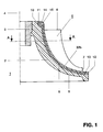
- Fig.1 einen ersten Teilschnitt durch einen Verdichter mit einer ersten Ausführungsform eines Verdichterrads,
- Fig.2 einen zweiten Teilschnitt durch die erste Ausführungsform des Verdichterrads,
- Fig.3 einen Teilschnitt durch einen Verdichter mit einer zweiten Ausführungsform eines Verdichterrads,
- Fig.4 einen Teilschnitt durch eine erste Ausführungsform einer Laufschaufel eines Verdichterrads, und
- Fig.5 einen Teilschnitt durch eine zweite Ausführungsform einer Laufschaufel eines Verdichterrads.
- 1 shows a first partial section through a compressor with a first embodiment of a compressor wheel,
- 2 shows a second partial section through the first embodiment of the compressor wheel,
- 3 shows a partial section through a compressor with a second embodiment of a compressor wheel,
- 4 shows a partial section through a first embodiment of a rotor blade of a compressor wheel, and
- 5 shows a partial section through a second embodiment of a rotor blade of a compressor wheel.
Bei allen Figuren sind gleich wirkende Elemente mit gleichen Bezugszeichen versehen. Alle für das unmittelbare Verständnis der Erfindung nicht erforderlichen Elemente sind nicht dargestellt.Elements with the same effect are provided with the same reference symbols in all the figures. All elements not necessary for the immediate understanding of the invention are not shown.
Die Fig.1 zeigt einen schematisch dargestellten Teilschnitt durch ein Verdichterrad 1, welches für die Verdichtung eines gasförmigen Fluids vorgesehen ist. Das Verdichterrad 1 weist eine Nabe 2 auf, die aus einem Kunststoff gefertigt ist, vorzugsweise aus einem mit Endlosfasern verstärkten thermoplastischen Material. Die Nabe 2 ist auf einer aus Metall gefertigten Hülse 3 befestigt, und ist gegen Verdrehen und gegen axiales Verrutschen gesichert. Die Nabe 2 und die Hülse 3 weisen eine gemeinsame Achse 4 auf, welche die Drehachse des Verdichterrads 1 darstellt. Die Hülse 3 weist eine zentrale Bohrung auf, die für die Aufnahme und Befestigung der nicht dargestellten Welle des Verdichterrads 1 vorgesehen ist. Auf der der Achse 4 abgewandten Seite der Nabe 2 sind Laufschaufeln 5 befestigt. Zwischen den Laufschaufeln 5 und dem nicht dargestellten, das Verdichterrad 1 einschliessenden Gehäuse des Verdichters sind nicht bezeichnete Strömungskanäle vorgesehen, in welche das gasförmige Medium einströmt und in welchen es auf bekannte Art beschleunigt und dadurch verdichtet wird.1 shows a schematically illustrated partial section through a
Die Nabe 2 wurde aus einem vorgefertigten, mit Endlosfasern verstärkten Kunststoffband gewickelt. Als Kunststoff eignen sich in diesem Fall besonders temperaturfeste Thermoplaste, und für die Verstärkung werden Kohlenstoffasern verwendet.The
Die Nabe 2 wurde auf einer der Innenkontur der Nabe 2 entsprechenden Lehre so gewickelt, dass die Kohlenstoffasern in Umfangsrichtung angeordnet sind, was eine besonders hohe Festigkeit der Nabe 2 in dieser Richtung zur Folge hat, wodurch vergleichsweise grosse Drehzahlen des Verdichterrads 1 und damit vergleichsweise grosse Wirkungsgrade des Verdichters möglich werden. Während des Wickelns wurde das thermoplastische Material des Bandes kurzzeitig erhitzt und mit der jeweils vorher aufgebrachten Lage des Bandes verschmolzen. Besonders eignet sich für diese gezielte und dosierte kurzfristige Erhitzung ein Laser. Derartige Thermoplast-Wickelverfahren unter Ausnutzung von Lasern als Energiequelle sind bekannt. Nach dem Abschluss des Wickelvorgangs wurde die so vorgefertigte Nabe 2 von der Lehre abgenommen und definitiv fertig bearbeitet. Insbesondere musste die Öffnung für die Aufnahme der Hülse 3 nachgearbeitet werden und zudem musste die äussere Oberfläche der Nabe 2 geglättet werden, um sie als Auflageund Klebefläche für die Befestigung der vorgefertigten Laufschaufeln 5 einsetzen zu können.The
Die Laufschaufeln 5 weisen jeweils eine strömungsgünstig ausgebildete Eintrittskante 6 auf, die auf der Eintrittsseite des gasförmigen Mediums in den Strömungskanal des Verdichters liegt. An der anderen Seite des Strömungskanals, bezogen auf die Strömung des gasförmigen Mediums stromabwärts, liegt jeweils die Austrittskante 7 der Laufschaufeln 5. Die Laufschaufeln 5 werden aus mehreren vorgefertigten, ebenfalls mit Endlosfasern verstärkten Teilen zusammengefügt, wie dies in den Fig.4 und 5 schematisch dargestellt ist. Auf diese Figuren wird nachfolgend eingegangen. Die Laufschaufeln 5 weisen als Basis jeweils eine Fussplatte 8 auf. Die der Oberfläche 9 der Nabe 2 zugewandte Seite der Fussplatte 8 ist dieser Oberfläche 9 so genau angepasst, dass diese Fussplatte 8 auf der Oberfläche 9 formschlüssig aufliegt. Die Oberfläche 9 weist auf der Eintrittsseite des Verdichterrads 1 einen Absatz 10 auf, auf welchem das eintrittsseitige Endstück 11 der Fussplatte 8 ebenfalls formschlüssig aufliegt.The blades 5 each have an aerodynamically designed
Die Fig.4 zeigt einen Teilschnitt durch eine erste Ausführungsform einer der Laufschaufeln 5 des Verdichterrads 1. Die Laufschaufeln 5 sind auf bekannte Art strömungsgünstig ausgebildet, die entsprechende sphärische Krümmung der Schaufelblätter ist in der Zeichnung, der besseren Anschaulichkeit halber, nicht dargestellt. Die Basis der Laufschaufeln 5 bildet die vorgeformte, gleichmässig dicke Fussplatte 8. Die Fussplatte 8 ist mit einer Wulst 26 versehen, die in das Innere der Laufschaufel 5 hineinragt und die sich in Richtung der Längsachse der Laufschaufel 5 erstreckt, wobei sie stromabwärts immer weniger ausgeprägt ist. Die Fussplatte 8 weist eine Unterseite 27 auf, die der Oberfläche 9 der Nabe 2 vollständig angeglichen ist. Die in der Unterseite 27 als Folge der Wulst 26 auftretende Vertiefung ist mittels einer Epoxidharzfüllung 28 so aufgefüllt, dass auch in diesem Bereich der Fussplatte 8 eine der Oberfläche 9 der Nabe 2 vollständig angeglichene Fläche vorhanden ist. Die Wulst 26 ist mit gleichmässig gerundeten Flanken versehen. Das Schaufelblatt wird durch zwei Seitenwände 29 und 30 gebildet. Die Seitenwände 29 und 30 sind aus gleichmässig dicken mit Endlosfasern verstärkten Kunststoffplatten gefertigt, sie schliessen einen in radialer Richtung enger werdenden Hohlraum 31 ein. Dieser Hohlraum 31 kann, um eine bessere Schwingungsdämpfung zu erreichen, ausgeschäumt werden. Der Hohlraum 31 ist im Bereich der Eintrittskante 6 der Laufschaufel 5 mittels einer nicht dargestellten, strömungsgünstig ausgebildeten Abdeckung verschlossen.4 shows a partial section through a first embodiment of one of the rotor blades 5 of the
Die Seitenwände 29 und 30 sind vorgeformt. Sie werden in einer Montagelehre auf die Fussplatte 8 aufgeklebt oder mit dieser verschweisst. Gleichzeitig werden die Seitenwände 29 und 30 im Bereich der Spitze der Laufschaufeln 5 flächig zusammengeklebt oder verschweisst. Die Seitenwände 29 und 30 sind so gestaltet, dass sie jeweils einen Fussteil 32a, 32b aufweisen, der formschlüssig auf die Oberfläche der Fussplatte 8 passt, und der mit einem Radius 33 übergeht in die annähernd radial verlaufende Partie der jeweiligen Seitenwand. Der Fussteil 32a ist der Seitenwand 29 zugeordnet und der Fussteil 32b der Seitenwand 30. Auf der stromaufwärts gelegenen Seite der Fussteile 32a und 32b sind jeweils Endstücke angeformt, welche dem Endstück 11 der Fussplatte 8 angepasst, formschlüssig auf der Oberfläche der Fussplatte 8 aufliegen. Der Radius 33 ist dem Radius der Flanke der Wulst 26 genau angepasst. Infolge der genauen Anpassung der Fussteile 32a und 32b der Seitenwände 29 und 30 an die Fussplatte 8 erhält man gleichmässige Klebefugen, die eine besonders haltbare Klebung ermöglichen.The
Die Fig.5 zeigt einen Teilschnitt durch eine zweite Ausführungsform einer Laufschaufel 5 eines Verdichterrads 1. Diese Ausführungsform unterscheidet sich von der Ausführungsform gemäss Fig.4 dadurch, dass die annähernd radial verlaufende Partie der Seitenwände 29 und 30 etwas aufgebaucht ist. Durch diese Formgebung wird erreicht, dass bei mechanischer Belastung der Laufschaufeln 5 die Spannungen zwischen den Fussteilen 32a und 32b der Seitenwände 29 und 30 und der Fussplatte 8 deutlich reduziert werden, die so ausgebildeten Laufschaufeln 5 sind deshalb besonders widerstandsfähig gegen hohe Fliehkräfte. Ein mit derartig ausgebildeten Laufschaufeln 5 ausgestattetes Verdichterrad 1 ist für besonders hohe Umfangsgeschwindigkeiten geeignet.5 shows a partial section through a second embodiment of a rotor blade 5 of a
Auf der Austrittsseite weist die Nabe 2 einen Bund 12 auf, gegen den das austrittsseitige Ende 13 der Laufschaufel 5 stösst. Das Ende 13 wird gebildet aus der mit den Fussteilen 32a und 32b bedeckten Fussplatte 8. Der Bund 12 ist an dieser Stelle gleich breit wie die Dicke dieses austrittsseitigen Endes 13 der Laufschaufel 5, sodass keine vorstehende Kante die Strömung des aus dem Verdichterrad 1 abströmenden verdichteten Mediums stört. Die Unterseite der Fussplatte 8 wird mit der Oberfläche 9 der Nabe 2 verklebt oder verschweisst. Die Fussplatten 8 sind so mit den Fussteilen 32a und 32b abgedeckt, dass beim fertigen Verdichterrad 1 die gesamte Oberfläche 9 bedeckt ist. In der hier gezeigten Ausführungsform des Verdichterrads 1 wird an der Eintrittsseite nach dem Verkleben und nach dem Aushärten des Klebstoffes zusätzlich eine Bandage 14 so angebracht, dass das Endstück 11 jeder Fussplatte 8 zusammen mit den Endstücken der Fussteile 32a und 32b gegen den Absatz 10 der Nabe 2 gedrückt wird. Die Bandage 14 wird aus einem vorgefertigten, mit Endlosfasern verstärkten Kunststoffband gewickelt. Als Kunststoff eignen sich in diesem Fall besonders temperaturfeste Thermoplaste, die mit Kohlenstoffasern verstärkt sind. Die Bandage 14 wurde so gewickelt, dass die Kohlenstoffasern in Umfangsrichtung liegen, was eine besonders hohe Festigkeit der Bandage 14 in dieser Richtung zur Folge hat, wodurch die Fussplatten 8 und die Fussteile 32a und 32b auch bei vergleichsweise grossen Drehzahlen des Verdichterrads 1 sicher gehalten werden. Während des Wickelns wird das thermoplastische Material des Bandes kurzzeitig erhitzt und mit der jeweils vorher aufgebrachten Lage des Bandes verschmolzen. Die Bandage 14 wird demnach mit Hilfe des gleichen Verfahrens gefertigt wie die Nabe 2. Nach dem Wickeln wird die Oberfläche 15 der Bandage 14 nachgearbeitet, um eine strömungsgünstige Form der Bandage 14 zu erreichen.On the outlet side, the
Beim Verdichterrad 1 gemäss Fig.1 werden die Laufschaufeln 5 durch die Verklebung bzw. durch die Verschweissung, die Bandage 14 und den Bund 12 gehalten. Bis zu vergleichsweise grossen Drehzahlen des Verdichterrads 1 genügt diese Befestigung vollauf. Werden jedoch noch grössere Drehzahlen verlangt, so werden die Laufschaufeln 5 zusätzlich mittels Metallnieten mit der Nabe 2 vernietet, und zwar werden die Fussteile 32a und 32b zusammen mit den Fussplatten 8 mit der Nabe 2 vernietet. Beim Vernieten wird darauf geachtet, dass die Nietköpfe die Strömung des Mediums in den Strömungskanälen nicht stören, da dies Wirkungsgradverluste zur Folge hätte.In the
Die Fig.2 zeigt einen schematisch dargestellten Teilschnitt durch das Verdichterrad gemäss Fig.1, und zwar zeigt es den Schnitt A-A. Die aus mehreren Komponenten zusammengefügten Laufschaufeln 5 weisen in dem Randbereich, wo sie die benachbarten Laufschaufeln 5 berühren, Abschrägungen 16a,16b auf, die ein Übereinanderschieben der Ränder der Laufschaufeln 5 und ein wirkungsvolles Verkleben derselben erlauben, wodurch eine geschlossene Oberfläche 17 der der Achse 4 zugewandten Seite des Strömungskanals 18 erreicht wird. Die gestrichelte Linie 19 deutet das Verdichtergehäuse an, welches den seitlich durch die Laufschaufeln 5 begrenzten Strömungskanal 18 nach aussen hin abschliesst.FIG. 2 shows a schematically represented partial section through the compressor wheel according to FIG. 1, specifically showing section A-A. The blades 5, which are assembled from several components, have
Die Fig.3 zeigt einen Teilschnitt durch eine zweite Ausführungsform eines Verdichterrads. Diese Ausführungsform unterscheidet sich von derjenigen gemäss Fig.1 dadurch, dass im Zwischenraum zwischen zwei Laufschaufeln 5 jeweils eine weitere Laufschaufel 20 vorgesehen ist, die eine Eintrittskante 21 aufweist, die stromabwärts der Eintrittskante 6 der Laufschaufeln 5 angeordnet ist. Jeder Strömungskanal wird stromabwärts durch die Laufschaufel 20 in zwei Strömungskanäle aufgeteilt. Die Laufschaufel 20 weist eine Austrittskante auf, die in der gleichen Ebene wie die Austrittskante 7 der Laufschaufeln 5 angeordnet ist. Die Laufschaufeln 20 sind entsprechend den Laufschaufeln 5 ausgebildet. Die Laufschaufeln 20 sind ebenfalls mit einer Fussplatte versehen auf welche die entsprechenden Fussteile aufgebracht worden sind. Diese Fussplatte und die mit ihr verbundenen Fussteile passen genau in Aussparungen der Fussteile 32a und 32b der Laufschaufeln 5, wobei die Laufschaufeln 20 jeweils formschlüssig unter die Laufschaufeln 5 geschoben werden. Die Laufschaufeln 5 halten die Laufschaufeln 20 zusätzlich zu ihrer Verklebung oder Verschweissung mittels einer schwalbenschwanzartigen Verzahnung. Die Laufschaufeln 20 werden demnach ähnlich auf der Nabe 2 befestigt wie die Laufschaufeln 5. Die Fussteile 32a und 32b der Laufschaufeln 5 weisen bei dieser Ausführung ebenso wie die Fussteile der Laufschaufeln 20 auf der stromabwärts gelegenen Seite jeweils angeformte Endstücke auf, welche dem austrittsseitigen Endstück 22 der Fussplatte 8 angepasst, formschlüssig auf der Oberfläche der Fussplatte 8 aufliegen. Das Endstück 22 liegt formschlüssig auf einem Absatz 23 der Nabe 2 auf. In der hier in Fig.3 gezeigten Ausführungsform des Verdichterrads 1 wird nach dem Verkleben bzw. Verschweissen der Laufschaufeln 5 und 20 und nach dem Aushärten des Klebstoffes eine Bandage 24 zusätzlich zur Bandage 14 so angebracht, dass die Endstücke 22 jeder der Laufschaufeln 5 und jeder der Laufschaufeln 20 zusammen mit den Endstücken der jeweiligen Fussteile gegen den Absatz 23 der Nabe 2 gedrückt werden. Die Bandage 24 wird, gleich wie die Bandage 14, aus einem vorgefertigten, mit Endlosfasern verstärkten Kunststoffband gewickelt und entsprechend verschweisst. Die Oberfläche der Bandage 24 wird anschliessend ebenfalls strömungsgünstig ausgebildet.3 shows a partial section through a second embodiment of a compressor wheel. This embodiment differs from that according to FIG. 1 in that in the space between two rotor blades 5 there is in each case a
Das Verdichterrad 1 gemäss Fig.3 weist zudem einen Auswuchtring 25 auf, der beim Wickeln in die Nabe 2 eingelassen wurde. Der Auswuchtring 25 ist aus Metall gefertigt. Beim Auswuchten des fertigen Verdichterrads 1 wird von diesem Auswuchtring 25 Material abgetragen, um bestehende Unwuchten zu beseitigen. Es ist auch möglich, die Hülse 3 mit einer grösseren Masse auszuführen und den nötigen Materialabtrag an dieser vorzunehmen, sodass der Auswuchtring 25 eingespart werden kann.The
Für die Verbindung der Seitenwände 29 und 30 mit der Fussplatte 8 und der Abdeckung der Eintrittskante 6 zu einer Laufschaufel 5 und für die Verbindung der Laufschaufeln 5 mit der Nabe 2 ist ein Kleber auf der Basis eines Phenolharzes vorgesehen, hier hat sich der Klebstoff HT 424 der Firma American Cyanamid Company, 1300 Revolution Street, Havre de Grace, MD 21087, als besonders geeignet erwiesen. Ferner ist auch der Klebstoff auf der Basis eines modifizierten Kondensations-Polyimides des gleichen Herstellers mit der Bezeichnung FM 36 gut für das hier beschriebene Zusammenfügen geeignet. Ausser dem Kleben ist für das Verbinden der Teile der Laufschaufeln 5 auch ein Schweissvorgang mit Hilfe eines Lasers oder eine Kombination beider Verfahren vorstellbar. Die Laufschaufeln 20 werden auf die gleiche Art zusammengefügt.For the connection of the
Das Band für die Herstellung der Nabe 2 und der Bandagen 14 und 24 weist eine Matrix aus einem Thermoplast auf. Als Thermoplast hat sich dabei insbesondere Polyphenylensulfid bewährt, ferner wurden mit Polyetheretherketon gute Resultate erreicht. Die Matrix aus Polyphenylensulfid wurde mit einem Volumengehalt an Kohlefasern von etwa 53% verstärkt. Der Querschnitt dieses Bandes betrug 5mm x 0,158mm. Der Elastizitätsmodul des Bandes ergab sich zu 114 GPa. Die Einsatztemperatur lag in diesem Fall bei etwa 220°C. Die Matrix aus Polyetheretherketon wurde mit einem Volumengehalt an Kohlefasern von 61% verstärkt. Der Querschnitt dieses Bandes betrug 5mm x 0,125mm. Der Elastizitätsmodul des Bandes ergab sich zu 134.000 MPa. Die Einsatztemperatur lag in diesem Fall bei etwa 280 °C.The band for the production of the
Als Material für die Herstellung der Bestandteile der Laufschaufeln 5,20 wird ein thermoplastischer Kunststoff eingesetzt, der mit als Endlosfasern ausgebildeten Kohlenstoffasern verstärkt ist. Dieses Material wird in Form von gleichmässig dicken Platten geliefert. Als besonders geeignet hat sich eine Matrix aus Polyetheretherketon mit einem Volumengehalt an Kohlefasern von 61% erwiesen. Diese Platten werden in Formen eingelegt und unter thermischer Beaufschlagung mit Hilfe eines der bekannten Verfahren in die definitive Gestalt gebracht, wobei darauf geachtet wird, dass die Endlosfasern in Richtung der dynamischen Hauptbeanspruchung der Laufschaufeln 5,20 ausgerichtet sind. Die so vorgefertigten Bestandteile, die Seitenwände 29 und 30 und die Fussplatte 8, der Laufschaufeln 5,20 werden dann, wie bereits beschrieben, in einer Montagelehre zur fertigen Laufschaufel 5 bzw. 20 zusammengefügt.A thermoplastic plastic is used as the material for the production of the components of the
- 11
- VerdichterradCompressor wheel
- 22nd
- Nabehub
- 33rd
- HülseSleeve
- 44th
- Achseaxis
- 55
- LaufschaufelnBlades
- 66
- EintrittskanteLeading edge
- 77
- AustrittskanteTrailing edge
- 88th
- FussplatteFootplate
- 99
- Oberflächesurface
- 1010th
- Absatzparagraph
- 1111
- EndstückTail
- 1212th
- BundFederation
- 1313
- EndeThe End
- 1414
- Bandagebandage
- 1515
- Oberflächesurface
- 16a,b16a, b
- AbschrägungenBevels
- 1717th
- Oberflächesurface
- 1818th
- StrömungsKanalFlow channel
- 1919th
- gestrichelte Liniedashed line
- 2020th
- LaufschaufelBlade
- 2121
- EintrittskanteLeading edge
- 2222
- EndstückTail
- 2323
- Absatzparagraph
- 2424th
- Bandagebandage
- 2525th
- AuswuchtringBalancing ring
- 2626
- Wulstbead
- 2727
- Unterseitebottom
- 2828
- EpoxidharzfüllungEpoxy resin filling
- 29,3029.30
- SeitenwandSide wall
- 3131
- Hohlraumcavity
- 32a,b32a, b
- FussteilFoot part
- 3333
- Radiusradius
Claims (10)
Applications Claiming Priority (2)
| Application Number | Priority Date | Filing Date | Title |
|---|---|---|---|
| DE19513508 | 1995-04-10 | ||
| DE19513508A DE19513508A1 (en) | 1995-04-10 | 1995-04-10 | compressor |
Publications (2)
| Publication Number | Publication Date |
|---|---|
| EP0737814A1 true EP0737814A1 (en) | 1996-10-16 |
| EP0737814B1 EP0737814B1 (en) | 2000-03-01 |
Family
ID=7759344
Family Applications (1)
| Application Number | Title | Priority Date | Filing Date |
|---|---|---|---|
| EP96810177A Expired - Lifetime EP0737814B1 (en) | 1995-04-10 | 1996-03-20 | Compressor |
Country Status (8)
| Country | Link |
|---|---|
| US (1) | US5632601A (en) |
| EP (1) | EP0737814B1 (en) |
| JP (1) | JPH08296590A (en) |
| KR (1) | KR960038140A (en) |
| CN (1) | CN1136142A (en) |
| CZ (1) | CZ95896A3 (en) |
| DE (2) | DE19513508A1 (en) |
| PL (1) | PL313679A1 (en) |
Cited By (5)
| Publication number | Priority date | Publication date | Assignee | Title |
|---|---|---|---|---|
| EP0942174A1 (en) * | 1998-03-11 | 1999-09-15 | ABB Solyvent Ventec | Composite material centrifugal fan rotor |
| WO2004016952A1 (en) * | 2002-07-26 | 2004-02-26 | Robert Bosch Gmbh | Combustion wheel |
| WO2004046559A1 (en) * | 2002-11-15 | 2004-06-03 | Daimlerchrysler Ag | Running wheel |
| DE202011052411U1 (en) * | 2011-12-21 | 2013-03-22 | Ebm-Papst Mulfingen Gmbh & Co. Kg | Paddle wheel for axial fans or radial and diagonal fans |
| WO2019028305A1 (en) * | 2017-08-04 | 2019-02-07 | Borgwarner Inc. | Polymeric compressor wheel with metal sleeve |
Families Citing this family (26)
| Publication number | Priority date | Publication date | Assignee | Title |
|---|---|---|---|---|
| DE19632893C2 (en) * | 1996-08-16 | 2001-02-08 | Industrieanlagen Betr Sgmbh Ia | Process for manufacturing missile components from fiber-reinforced ceramic |
| FI101565B (en) * | 1997-01-17 | 1998-07-15 | Flaekt Woods Ab | Evaporator fan and its impeller |
| FI101564B (en) * | 1997-01-17 | 1998-07-15 | Flaekt Woods Ab | High pressure fan |
| DE19723845A1 (en) * | 1997-06-06 | 1998-12-10 | Abb Research Ltd | Polymer composite rotor blade manufacture |
| US6224339B1 (en) | 1998-07-08 | 2001-05-01 | Allison Advanced Development Company | High temperature airfoil |
| DE19912715A1 (en) * | 1999-03-20 | 2000-09-21 | Abb Research Ltd | Compressor wheel has nave and running blades of one-piece aluminum structure and hollow core and at end of nave |
| EP1633985A1 (en) * | 2003-01-17 | 2006-03-15 | Robert Bosch Gmbh | Impeller for turbomachinery |
| EP1627726A1 (en) * | 2004-08-18 | 2006-02-22 | ABB Turbo Systems AG | Fibre reinforced compressor |
| EP2302172A1 (en) | 2004-11-12 | 2011-03-30 | Board of Trustees of Michigan State University | Machine comprising an electromagnetic woven rotor and manufacturing method |
| US8142160B2 (en) * | 2006-10-24 | 2012-03-27 | Lg Electronics Inc. | High speed type impeller having a reinforcing ring |
| US8182213B2 (en) * | 2009-04-22 | 2012-05-22 | Pratt & Whitney Canada Corp. | Vane assembly with removable vanes |
| IT1394295B1 (en) | 2009-05-08 | 2012-06-06 | Nuovo Pignone Spa | CENTRIFUGAL IMPELLER OF THE CLOSED TYPE FOR TURBOMACCHINE, COMPONENT FOR SUCH A IMPELLER, TURBOMACCHINA PROVIDED WITH THAT IMPELLER AND METHOD OF REALIZING SUCH A IMPELLER |
| IT1397057B1 (en) | 2009-11-23 | 2012-12-28 | Nuovo Pignone Spa | CENTRIFUGAL AND TURBOMACHINE IMPELLER |
| IT1397058B1 (en) | 2009-11-23 | 2012-12-28 | Nuovo Pignone Spa | CENTRIFUGAL IMPELLER MOLD, MOLD INSERTS AND METHOD TO BUILD A CENTRIFUGAL IMPELLER |
| US8794914B2 (en) | 2010-11-23 | 2014-08-05 | GM Global Technology Operations LLC | Composite centrifugal compressor wheel |
| ITCO20110064A1 (en) | 2011-12-14 | 2013-06-15 | Nuovo Pignone Spa | ROTARY MACHINE INCLUDING A ROTOR WITH A COMPOSITE IMPELLER AND A METAL SHAFT |
| US9777579B2 (en) | 2012-12-10 | 2017-10-03 | General Electric Company | Attachment of composite article |
| US9797257B2 (en) | 2012-12-10 | 2017-10-24 | General Electric Company | Attachment of composite article |
| RU2522152C1 (en) * | 2013-03-21 | 2014-07-10 | Открытое акционерное общество Научно-производственное объединение "Искра" | Rotor of centrifugal compressor |
| JP6131085B2 (en) * | 2013-04-01 | 2017-05-17 | 株式会社神戸製鋼所 | Rotating machine, impeller used for rotating machine, and manufacturing method of impeller |
| US20140322019A1 (en) * | 2013-04-30 | 2014-10-30 | Dresser Inc. | Rotary element and compressor device comprised thereof |
| ITCO20130067A1 (en) | 2013-12-17 | 2015-06-18 | Nuovo Pignone Srl | IMPELLER WITH PROTECTION ELEMENTS AND CENTRIFUGAL COMPRESSOR |
| CA2945652C (en) | 2014-05-05 | 2020-11-03 | Horton, Inc. | Composite fan |
| JP6309884B2 (en) * | 2014-11-25 | 2018-04-11 | 三菱重工業株式会社 | Impeller and rotating machine |
| JP6210459B2 (en) * | 2014-11-25 | 2017-10-11 | 三菱重工業株式会社 | Impeller and rotating machine |
| DE102016108762A1 (en) * | 2016-05-12 | 2017-11-16 | Man Diesel & Turbo Se | centrifugal compressors |
Citations (10)
| Publication number | Priority date | Publication date | Assignee | Title |
|---|---|---|---|---|
| US3521973A (en) * | 1968-08-16 | 1970-07-28 | Anpol Research Corp | Fan construction |
| GB1341578A (en) * | 1972-08-20 | 1973-12-25 | British Leyland Truck & Bus | Rotary compressors |
| EP0115451A2 (en) * | 1983-01-26 | 1984-08-08 | Arap - Applications Rationnelles De La Physique S.A.R.L. | Rotor for a centrifugal compressor and method of manufacture |
| FR2631083A1 (en) * | 1988-05-03 | 1989-11-10 | Plastiremo | Composite wheel for a centrifugal compressor and method for manufacturing it |
| EP0348674A1 (en) * | 1988-06-29 | 1990-01-03 | Asea Brown Boveri Ag | Device for extending the surge margin of a radial compressor |
| US5145320A (en) * | 1990-08-28 | 1992-09-08 | The United States Of America As Represented By The Secretary Of The Navy | Mass loaded composite rotor for vibro-acoustic application |
| DE4139293A1 (en) * | 1991-11-29 | 1993-06-03 | Inst Verbundwerkstoffe Gmbh | Pump impeller and associated composite - has modular construction of box or U=shaped sections with disc faces and mfd. by resin injection, winding or pressing |
| EP0593797A1 (en) * | 1992-10-17 | 1994-04-27 | Asea Brown Boveri Ag | Stabilizing device for the increase of the surge margin of a compressor |
| DE4409629A1 (en) * | 1993-03-25 | 1994-09-29 | Ozen Sa | Pump rotor and method for manufacturing it |
| DE4321173A1 (en) * | 1993-06-25 | 1995-01-12 | Inst Luft & Kaeltetechnik Ggmbh | Refrigerant turbo compressor |
Family Cites Families (10)
| Publication number | Priority date | Publication date | Assignee | Title |
|---|---|---|---|---|
| US1535417A (en) * | 1924-07-05 | 1925-04-28 | Ingersoll Rand Co | Open impeller |
| US2848190A (en) * | 1952-10-02 | 1958-08-19 | Power Jets Res & Dev Ltd | Radial flow turbo-machines |
| US3070844A (en) * | 1952-12-15 | 1963-01-01 | Studebaker Packard Corp | Machine for making stator blades and the like |
| US2848192A (en) * | 1953-03-12 | 1958-08-19 | Gen Motors Corp | Multi-piece hollow turbine bucket |
| GB1279016A (en) * | 1969-05-30 | 1972-06-21 | Normalair Garrett Ltd | Improvements in or relating to methods of manufacture of bladed or toothed components |
| DE2618829C3 (en) * | 1976-04-29 | 1983-03-03 | Klein, Schanzlin & Becker Ag, 6710 Frankenthal | Storage of a multistage centrifugal pump |
| US4260327A (en) * | 1979-07-25 | 1981-04-07 | General Electric Company | Guide vane assembly for reverse flow cooled dynamoelectric machine |
| DE3307386A1 (en) * | 1983-03-02 | 1984-09-06 | Wilden Kg, 8473 Pfreimd | Impeller for pumps, compressors, fans and the like |
| GB2161110B (en) * | 1984-07-07 | 1988-03-23 | Rolls Royce | An annular bladed member having an integral shroud and a method of manufacture thereof |
| US5431536A (en) * | 1994-02-01 | 1995-07-11 | General Motors Corporation | Molded torque converter stator and integral race for a one-way torque transmitter |
-
1995
- 1995-04-10 DE DE19513508A patent/DE19513508A1/en not_active Withdrawn
-
1996
- 1996-03-14 US US08/615,884 patent/US5632601A/en not_active Expired - Fee Related
- 1996-03-20 DE DE59604509T patent/DE59604509D1/en not_active Expired - Fee Related
- 1996-03-20 EP EP96810177A patent/EP0737814B1/en not_active Expired - Lifetime
- 1996-03-27 KR KR1019960008653A patent/KR960038140A/en not_active Withdrawn
- 1996-04-02 CZ CZ96958A patent/CZ95896A3/en unknown
- 1996-04-09 PL PL96313679A patent/PL313679A1/en unknown
- 1996-04-10 CN CN96107300A patent/CN1136142A/en active Pending
- 1996-04-10 JP JP8088604A patent/JPH08296590A/en active Pending
Patent Citations (10)
| Publication number | Priority date | Publication date | Assignee | Title |
|---|---|---|---|---|
| US3521973A (en) * | 1968-08-16 | 1970-07-28 | Anpol Research Corp | Fan construction |
| GB1341578A (en) * | 1972-08-20 | 1973-12-25 | British Leyland Truck & Bus | Rotary compressors |
| EP0115451A2 (en) * | 1983-01-26 | 1984-08-08 | Arap - Applications Rationnelles De La Physique S.A.R.L. | Rotor for a centrifugal compressor and method of manufacture |
| FR2631083A1 (en) * | 1988-05-03 | 1989-11-10 | Plastiremo | Composite wheel for a centrifugal compressor and method for manufacturing it |
| EP0348674A1 (en) * | 1988-06-29 | 1990-01-03 | Asea Brown Boveri Ag | Device for extending the surge margin of a radial compressor |
| US5145320A (en) * | 1990-08-28 | 1992-09-08 | The United States Of America As Represented By The Secretary Of The Navy | Mass loaded composite rotor for vibro-acoustic application |
| DE4139293A1 (en) * | 1991-11-29 | 1993-06-03 | Inst Verbundwerkstoffe Gmbh | Pump impeller and associated composite - has modular construction of box or U=shaped sections with disc faces and mfd. by resin injection, winding or pressing |
| EP0593797A1 (en) * | 1992-10-17 | 1994-04-27 | Asea Brown Boveri Ag | Stabilizing device for the increase of the surge margin of a compressor |
| DE4409629A1 (en) * | 1993-03-25 | 1994-09-29 | Ozen Sa | Pump rotor and method for manufacturing it |
| DE4321173A1 (en) * | 1993-06-25 | 1995-01-12 | Inst Luft & Kaeltetechnik Ggmbh | Refrigerant turbo compressor |
Cited By (9)
| Publication number | Priority date | Publication date | Assignee | Title |
|---|---|---|---|---|
| EP0942174A1 (en) * | 1998-03-11 | 1999-09-15 | ABB Solyvent Ventec | Composite material centrifugal fan rotor |
| WO1999046511A1 (en) * | 1998-03-11 | 1999-09-16 | Abb Solyvent-Ventec | Composite material centrifugal wheel |
| FR2776030A1 (en) * | 1998-03-11 | 1999-09-17 | Abb Solyvent Ventec | CENTRIFUGAL VENTILATION WHEEL IN COMPOSITE MATERIALS |
| WO2004016952A1 (en) * | 2002-07-26 | 2004-02-26 | Robert Bosch Gmbh | Combustion wheel |
| WO2004046559A1 (en) * | 2002-11-15 | 2004-06-03 | Daimlerchrysler Ag | Running wheel |
| DE202011052411U1 (en) * | 2011-12-21 | 2013-03-22 | Ebm-Papst Mulfingen Gmbh & Co. Kg | Paddle wheel for axial fans or radial and diagonal fans |
| WO2019028305A1 (en) * | 2017-08-04 | 2019-02-07 | Borgwarner Inc. | Polymeric compressor wheel with metal sleeve |
| US10393134B2 (en) | 2017-08-04 | 2019-08-27 | Borgwarner Inc. | Polymeric compressor wheel with metal sleeve |
| WO2019028304A3 (en) * | 2017-08-04 | 2020-02-13 | Borgwarner Inc. | Polymeric compressor wheel with metal sleeve |
Also Published As
| Publication number | Publication date |
|---|---|
| CN1136142A (en) | 1996-11-20 |
| KR960038140A (en) | 1996-11-21 |
| US5632601A (en) | 1997-05-27 |
| JPH08296590A (en) | 1996-11-12 |
| PL313679A1 (en) | 1996-10-14 |
| CZ95896A3 (en) | 1996-10-16 |
| DE59604509D1 (en) | 2000-04-06 |
| DE19513508A1 (en) | 1996-10-17 |
| EP0737814B1 (en) | 2000-03-01 |
Similar Documents
| Publication | Publication Date | Title |
|---|---|---|
| EP0737814B1 (en) | Compressor | |
| EP0754863B1 (en) | Fan | |
| EP1914383B1 (en) | Fibre reinforced composite fan blade | |
| DE102011078951B4 (en) | Method for producing a rotor blade for a wind energy plant, sandwich preform and rotor blade for a wind energy plant | |
| DE3879287T2 (en) | FRP SHEET AND ITS PRODUCTION PROCESS. | |
| DE19903550C1 (en) | Blade root for propeller and rotor blades | |
| DE69724018T2 (en) | Multicomponent gas turbine blade | |
| EP1832733B1 (en) | Inlet cone made of a fibre composite for a gas turbine plant and method for its manufacture | |
| WO1987000249A1 (en) | Water pump rotor | |
| EP3018342B1 (en) | Method for producing a rotor blade of a wind turbine | |
| WO2014060274A1 (en) | Exhaust gas turbocharger shaft having an impeller | |
| EP3199451A1 (en) | Nose cone for a fan of an aircraft engine | |
| EP2212561B1 (en) | Housing for a radial compressor | |
| EP2318719A1 (en) | Rotor for a radial machine | |
| EP3106673B1 (en) | Fan with at least one fan wheel and/or further fan parts and method for producing a fan part of a fan | |
| DE102009004813B4 (en) | Fiber-reinforced plastic panel with laminated bushing insert | |
| WO2019115703A1 (en) | Diagonal fan wheel with increased strength | |
| DE3620097A1 (en) | Wheel for motor vehicles | |
| DE3016862C2 (en) | Rim wheel | |
| EP4025437A1 (en) | Running wheel for a bicycle | |
| EP0085127B1 (en) | Rotor, in particular for rotary wing aircraft, with fibre-reinforced plastic hub | |
| EP1627726A1 (en) | Fibre reinforced compressor | |
| DE10256778A1 (en) | Oscillation dampers for damping vibrations produced by blades in turbines or compressors are arranged between neighboring blades or a rotor and are made from a light rigid non-metallic material | |
| DE4418051C2 (en) | Compressor wheel | |
| EP3015702B1 (en) | Rotor blade for a wind turbine and method for producing a rotor blade |
Legal Events
| Date | Code | Title | Description |
|---|---|---|---|
| PUAI | Public reference made under article 153(3) epc to a published international application that has entered the european phase |
Free format text: ORIGINAL CODE: 0009012 |
|
| AK | Designated contracting states |
Kind code of ref document: A1 Designated state(s): DE FR GB |
|
| 17P | Request for examination filed |
Effective date: 19970310 |
|
| GRAG | Despatch of communication of intention to grant |
Free format text: ORIGINAL CODE: EPIDOS AGRA |
|
| GRAG | Despatch of communication of intention to grant |
Free format text: ORIGINAL CODE: EPIDOS AGRA |
|
| GRAH | Despatch of communication of intention to grant a patent |
Free format text: ORIGINAL CODE: EPIDOS IGRA |
|
| 17Q | First examination report despatched |
Effective date: 19990719 |
|
| GRAH | Despatch of communication of intention to grant a patent |
Free format text: ORIGINAL CODE: EPIDOS IGRA |
|
| GRAA | (expected) grant |
Free format text: ORIGINAL CODE: 0009210 |
|
| AK | Designated contracting states |
Kind code of ref document: B1 Designated state(s): DE FR GB |
|
| PG25 | Lapsed in a contracting state [announced via postgrant information from national office to epo] |
Ref country code: GB Free format text: LAPSE BECAUSE OF FAILURE TO SUBMIT A TRANSLATION OF THE DESCRIPTION OR TO PAY THE FEE WITHIN THE PRESCRIBED TIME-LIMIT Effective date: 20000301 Ref country code: FR Free format text: LAPSE BECAUSE OF FAILURE TO SUBMIT A TRANSLATION OF THE DESCRIPTION OR TO PAY THE FEE WITHIN THE PRESCRIBED TIME-LIMIT Effective date: 20000301 |
|
| REF | Corresponds to: |
Ref document number: 59604509 Country of ref document: DE Date of ref document: 20000406 |
|
| EN | Fr: translation not filed | ||
| GBV | Gb: ep patent (uk) treated as always having been void in accordance with gb section 77(7)/1977 [no translation filed] |
Effective date: 20000301 |
|
| PLBE | No opposition filed within time limit |
Free format text: ORIGINAL CODE: 0009261 |
|
| STAA | Information on the status of an ep patent application or granted ep patent |
Free format text: STATUS: NO OPPOSITION FILED WITHIN TIME LIMIT |
|
| PG25 | Lapsed in a contracting state [announced via postgrant information from national office to epo] |
Ref country code: DE Free format text: LAPSE BECAUSE OF NON-PAYMENT OF DUE FEES Effective date: 20010103 |
|
| 26N | No opposition filed |