EP0737804A2 - Gas turbine fuel heating apparatus - Google Patents
Gas turbine fuel heating apparatus Download PDFInfo
- Publication number
- EP0737804A2 EP0737804A2 EP96104254A EP96104254A EP0737804A2 EP 0737804 A2 EP0737804 A2 EP 0737804A2 EP 96104254 A EP96104254 A EP 96104254A EP 96104254 A EP96104254 A EP 96104254A EP 0737804 A2 EP0737804 A2 EP 0737804A2
- Authority
- EP
- European Patent Office
- Prior art keywords
- fuel
- air
- cooling
- turbine
- gas turbine
- Prior art date
- Legal status (The legal status is an assumption and is not a legal conclusion. Google has not performed a legal analysis and makes no representation as to the accuracy of the status listed.)
- Granted
Links
Images


Classifications
-
- F—MECHANICAL ENGINEERING; LIGHTING; HEATING; WEAPONS; BLASTING
- F02—COMBUSTION ENGINES; HOT-GAS OR COMBUSTION-PRODUCT ENGINE PLANTS
- F02C—GAS-TURBINE PLANTS; AIR INTAKES FOR JET-PROPULSION PLANTS; CONTROLLING FUEL SUPPLY IN AIR-BREATHING JET-PROPULSION PLANTS
- F02C7/00—Features, components parts, details or accessories, not provided for in, or of interest apart form groups F02C1/00 - F02C6/00; Air intakes for jet-propulsion plants
- F02C7/12—Cooling of plants
- F02C7/16—Cooling of plants characterised by cooling medium
- F02C7/18—Cooling of plants characterised by cooling medium the medium being gaseous, e.g. air
- F02C7/185—Cooling means for reducing the temperature of the cooling air or gas
-
- F—MECHANICAL ENGINEERING; LIGHTING; HEATING; WEAPONS; BLASTING
- F02—COMBUSTION ENGINES; HOT-GAS OR COMBUSTION-PRODUCT ENGINE PLANTS
- F02C—GAS-TURBINE PLANTS; AIR INTAKES FOR JET-PROPULSION PLANTS; CONTROLLING FUEL SUPPLY IN AIR-BREATHING JET-PROPULSION PLANTS
- F02C7/00—Features, components parts, details or accessories, not provided for in, or of interest apart form groups F02C1/00 - F02C6/00; Air intakes for jet-propulsion plants
- F02C7/22—Fuel supply systems
- F02C7/224—Heating fuel before feeding to the burner
Definitions
- the present invention relates to a gas turbine fuel heating apparatus for heating gas turbine fuel by use of heat to be wasted.
- TCA cooler turbine cooling air cooler
- Figs. 3 to 5 show examples of such gas turbine fuel heating systems in the prior art.
- FIG. 3 Shown in Fig. 3 is a system in which air of which temperature is elevated in compression stages of a gas turbine driven compressor is extracted and fuel is heated at a heater 21 by heat of the extracted air so that the heat of the extracted air to be wasted is made use of for heating the fuel. Said air is further cooled at a cooler 22 by a cooling water to be used as a cooling air for a rotor, moving and stationary blades etc.
- Shown in Fig. 4 is a system in which fuel is heated by making heat exchange at a heat exchanger 26 between a normal temperature fuel supplied with pressure from a fuel tank 23 to a combustor 24 and a high temperature cooling air extracted from a compressor 25 so that the high temperature air is cooled to be used for cooling of a rotor, moving and stationary blades etc.
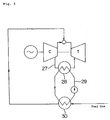
- Shown in Fig. 5 is a system to make use of heat to be wasted in which heat exchange is made at a cooler 28 between a turbine cooling air 27 extracted from a compressor and a cooling medium (pressurized water) 29 to heat the pressurized water 29 so that the gas turbine fuel is heated at a heater 30 by the pressurized water.
- heat exchange is made at a cooler 28 between a turbine cooling air 27 extracted from a compressor and a cooling medium (pressurized water) 29 to heat the pressurized water 29 so that the gas turbine fuel is heated at a heater 30 by the pressurized water.
- the system shown in Fig. 3 has such shortcomings that it, being of an indirect heating method using water, requires a separate heater 21 and cooler 22, which results in a high amount of initial investment cost.
- the system shown in Fig. 4 is of a direct heating method using oil as fuel in which the fuel oil is heated by extracted air so that the extracted air is cooled by the fuel oil.
- Fig. 5 the system shown in Fig. 5, is of an indirect heating method in which pressurized water heated by extracted air heats fuel.
- This system has also shortcomings that it requires a separate cooler 28 and heater 30 to result in a high amount of initial investment cost.
- One feature of the gas turbine fuel heating apparatus is that it comprises a TCA cooler of air cooling type for cooling a turbine cooling air and a fuel heater provided connectedly to the leaving side of a refrigerant air of said TCA cooler of air cooling type for heating the fuel by said refrigerant air.
- TCA cooler of air cooling type comprises a plurality of motor driven fans to supply the refrigerant air.
- gas turbine fuel heating apparatus is that said fuel heater is constructed substantially in same size as said TCA cooler of air cooling type and is provided directly lappedly on said TCA cooler of air cooling type.
- Still further feature of the gas turbine fuel heating apparatus according to the present invention is that the turbine cooling air of said TCA cooler of air cooling type and the fuel of said fuel heater flow in opposite directions each other in said TCA cooler of air cooling type and said fuel heater, respectively.
- the fuel heated by said fuel heater is gas or a liquid fuel like oil.
- the apparatus has a long useful life. Further, as the TCA cooler and the fuel heater are provided separately each other, safety at the time of fuel leakage can be ensured.
- the apparatus is constructed so as to make the fan revolution changeable to maintain a uniform temperature of the refrigerant air leaving the TCA cooler and entering the fuel heater.
- the initial investment cost can be lowered as compared with the indirect heating system using pressurized water.
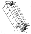
- a TCA cooler 1 comprises an outer shell 2, disposed on the upper part, containing a tube nest (not shown in the figure) through which a cooling air to cool a rotor, moving and stationary blades etc. of gas turbine flows and a plurality of motor driven fans 3, disposed on the lower part, to supply a refrigerant air (atmospheric air) to cool the tube nest.
- a refrigerant air atmospheric air
- a pressurized and temperature-risen air extracted from a compressor or a pressurized and temperature-risen air extracted from compression stages of a gas turbine driven compressor, etc. is used.
- a fuel heater 4 is provided connectedly so that an indirect heating construction is employed in which fuel is indirectly heated by the refrigerant air heated at the TCA cooler and leaving there.
- a tube nest through which fuel gas or fuel oil flows is contained.
- Said fuel heater 4 and said TCA cooler 1 are constructed substantially in same size, respectively, and are arranged so that the fuel heater 4 is directly lapped on the TCA cooler 1.
- an inlet side header 6a to introduce the cooling air and an outlet side header 6b are provided on both sides of the TCA cooler 1.
- an inlet side header 7a of fuel is provided on one side of the fuel heater 4 where said header 6b is provided, and on the other side of the fuel heater 4 where said header 6a is provided, an outlet side header 7b of fuel is provided.
- the cooling air and the fuel flows in the TCA cooler 1 and the fuel heater 4, respectively, in opposite directions each other as shown by the arrows A and B.
- numeral 8 in Fig. 2 designates a walkway for headers.
- finned tubes are used in order to enhance the heat exchange performance with the refrigerant air.
- the refrigerant air (atmospheric air) supplied by the fans 3 cools the cooling air flowing in the exchanger tubes of the tube nest of the TCA cooler 1 and is heated itself. Said cooling air so cooled is sent from the header 6b to the rotor, the moving and stationary blades etc. of gas turbine and cools them.
- the air heated at the tube nest of the TCA cooler 1 enters the tube nest of the fuel heater 4 on the upper side of the TCA cooler 1 and heats there the fuel flowing in the heat exchanger tubes of said tube nest and then the heated fuel is sent from the header 7b to a combustor of gas turbine.
- the heat to be wasted outside the system can be effectively utilized, and as the fuel is indirectly heated by the heat of the cooling air, the useful life of the apparatus can be elongated.
- cooling of the cooling air and heating of the fuel is done by the TCA cooler 1 and the fuel heater 4 provided connectedly thereto, respectively, the initial investment cost can be lowered as compared with said indirect heating method using pressurized water in the prior art.
- the gas turbine fuel heating apparatus As the heat of the refrigerant air which cools the cooling air for cooling the rotor, the moving and stationary blades etc. of gas turbine and leaves the TCA cooler is effectively made use of for heating the fuel at the fuel heater, the efficiency of gas turbine can be enhanced, and as the construction is simple in that the TCA cooler and the fuel heater are provided connectedly each other and the refrigerant air leaving the TCA cooler is passed through the fuel heater, the initial investment cost is low as compared with an indirect heating method using water in the prior art or an indirect heating method using pressurized water in the prior art, and further a risk of a fuel leaking and making contact with a high pressure air in an indirect heating method in the prior art can be avoided.
- the present invention can contribute to enhancement of gas turbine efficiency and to enhancement of gas turbine reliability.
Abstract
Description
- The present invention relates to a gas turbine fuel heating apparatus for heating gas turbine fuel by use of heat to be wasted.
- Generally in the prior art, in order to cool a rotor, moving and stationary blades etc. of gas turbine, a high pressure air in the turbine casing is extracted and cooled at a turbine cooling air cooler (herein referred to as "TCA cooler") of air cooling type to be used as a cooling air. However, if a gas turbine is of a large size type, the heat to be wasted outside the system becomes a huge amount and the efficiency (fuel consumption) of gas turbine becomes worse.
- So, systems to enhance the efficiency (fuel consumption) by heating the gas turbine fuel by use of the heat to be wasted outside the system have been disclosed. Figs. 3 to 5 show examples of such gas turbine fuel heating systems in the prior art.
- Shown in Fig. 3 is a system in which air of which temperature is elevated in compression stages of a gas turbine driven compressor is extracted and fuel is heated at a
heater 21 by heat of the extracted air so that the heat of the extracted air to be wasted is made use of for heating the fuel. Said air is further cooled at acooler 22 by a cooling water to be used as a cooling air for a rotor, moving and stationary blades etc. - Shown in Fig. 4 is a system in which fuel is heated by making heat exchange at a
heat exchanger 26 between a normal temperature fuel supplied with pressure from afuel tank 23 to acombustor 24 and a high temperature cooling air extracted from acompressor 25 so that the high temperature air is cooled to be used for cooling of a rotor, moving and stationary blades etc. - Shown in Fig. 5 is a system to make use of heat to be wasted in which heat exchange is made at a
cooler 28 between aturbine cooling air 27 extracted from a compressor and a cooling medium (pressurized water) 29 to heat the pressurizedwater 29 so that the gas turbine fuel is heated at aheater 30 by the pressurized water. - In the gas turbine fuel heating systems in the prior art as described above, the system shown in Fig. 3 has such shortcomings that it, being of an indirect heating method using water, requires a
separate heater 21 andcooler 22, which results in a high amount of initial investment cost. - The system shown in Fig. 4 is of a direct heating method using oil as fuel in which the fuel oil is heated by extracted air so that the extracted air is cooled by the fuel oil.
- And the system shown in Fig. 5, is of an indirect heating method in which pressurized water heated by extracted air heats fuel. This system has also shortcomings that it requires a
separate cooler 28 andheater 30 to result in a high amount of initial investment cost. - Thus, as a whole, those shown in Figs. 3 and 5 require a high initial investment cost and that shown in Fig. 4 has a risk that fuel may leak due to aged deterioration of a heat exchanger and come to contact with a high temperature air.
- It is therefore an object of the present invention to provide a gas turbine fuel heating apparatus to dissolve the above-mentioned shortcomings in the prior art.
- One feature of the gas turbine fuel heating apparatus according to the present invention is that it comprises a TCA cooler of air cooling type for cooling a turbine cooling air and a fuel heater provided connectedly to the leaving side of a refrigerant air of said TCA cooler of air cooling type for heating the fuel by said refrigerant air.
- Another feature of the gas turbine fuel heating apparatus according to the present invention is that said TCA cooler of air cooling type comprises a plurality of motor driven fans to supply the refrigerant air.
- Further feature of the gas turbine fuel heating apparatus according to the present invention is that said fuel heater is constructed substantially in same size as said TCA cooler of air cooling type and is provided directly lappedly on said TCA cooler of air cooling type.
- Still further feature of the gas turbine fuel heating apparatus according to the present invention is that the turbine cooling air of said TCA cooler of air cooling type and the fuel of said fuel heater flow in opposite directions each other in said TCA cooler of air cooling type and said fuel heater, respectively.
- Further feature of the gas turbine fuel heating apparatus according to the present invention is that heat exchanger tubes contained in said TCA cooler of air cooling type and said fuel heater, in which said turbine cooling air and said fuel flow, are finned tubes.
- Further feature of the gas turbine fuel heating apparatus according to the present invention is that the fuel heated by said fuel heater is gas or a liquid fuel like oil.
- According to the present invention, as the refrigerant air is heated by cooling the turbine cooling air and the fuel is heated indirectly by the refrigerant air of the outlet side of the TCA cooler, the apparatus has a long useful life. Further, as the TCA cooler and the fuel heater are provided separately each other, safety at the time of fuel leakage can be ensured.
- Further, not only gas but also a liquid fuel like oil can be used as a fuel, and even if the atmospheric air temperature changes, the apparatus is constructed so as to make the fan revolution changeable to maintain a uniform temperature of the refrigerant air leaving the TCA cooler and entering the fuel heater.
- Furthermore, as cooling of the turbine cooling air and heating of the fuel are made at the TCA cooler and the fuel heater provided connectedly thereto, respectively, the initial investment cost can be lowered as compared with the indirect heating system using pressurized water.
- In the accompanying drawings:
- Fig. 1 is an explanatory drawing of an example of a preferred embodiment according to the present invention.
- Fig. 2 is a perspective view of said preferred embodiment.
- Fig. 3 is a schematic drawing of an example of a gas turbine fuel heating apparatus in the prior art.
- Fig. 4 is a schematic drawing of another example of a gas turbine fuel heating apparatus in the prior art.
- Fig. 5 is a schematic drawing of a further example of a gas turbine fuel heating apparatus in the prior art.
- One preferred embodiment according to the present invention is described with reference to Figs. 1 and 2. As shown in Fig. 1, a TCA cooler 1 comprises an
outer shell 2, disposed on the upper part, containing a tube nest (not shown in the figure) through which a cooling air to cool a rotor, moving and stationary blades etc. of gas turbine flows and a plurality of motor drivenfans 3, disposed on the lower part, to supply a refrigerant air (atmospheric air) to cool the tube nest. As said cooling air, a pressurized and temperature-risen air extracted from a compressor or a pressurized and temperature-risen air extracted from compression stages of a gas turbine driven compressor, etc. is used. - On the upper side of the TCA cooler 1 which is the leaving side of the refrigerant air of the TCA cooler 1, a
fuel heater 4 is provided connectedly so that an indirect heating construction is employed in which fuel is indirectly heated by the refrigerant air heated at the TCA cooler and leaving there. Within thefuel heater 4, a tube nest through which fuel gas or fuel oil flows is contained. - Said
fuel heater 4 and said TCA cooler 1 are constructed substantially in same size, respectively, and are arranged so that thefuel heater 4 is directly lapped on the TCA cooler 1. On both sides of the TCA cooler 1, aninlet side header 6a to introduce the cooling air and anoutlet side header 6b are provided. And on one side of thefuel heater 4 where saidheader 6b is provided, an inlet side header 7a of fuel is provided, and on the other side of thefuel heater 4 where saidheader 6a is provided, anoutlet side header 7b of fuel is provided. Thus, the cooling air and the fuel flows in the TCA cooler 1 and thefuel heater 4, respectively, in opposite directions each other as shown by the arrows A and B. Incidentally,numeral 8 in Fig. 2 designates a walkway for headers. - For heat exchanger tubes of multitubular type to construct the tube nests contained in said TCA cooler 1 and said
fuel heater 4, finned tubes are used in order to enhance the heat exchange performance with the refrigerant air. - In this preferred embodiment, the refrigerant air (atmospheric air) supplied by the
fans 3 cools the cooling air flowing in the exchanger tubes of the tube nest of the TCA cooler 1 and is heated itself. Said cooling air so cooled is sent from theheader 6b to the rotor, the moving and stationary blades etc. of gas turbine and cools them. The air heated at the tube nest of the TCA cooler 1 enters the tube nest of thefuel heater 4 on the upper side of the TCA cooler 1 and heats there the fuel flowing in the heat exchanger tubes of said tube nest and then the heated fuel is sent from theheader 7b to a combustor of gas turbine. - As described above, in this preferred embodiment, as the fuel is heated by the air which cools the cooling air and leaves the TCA cooler 1, the heat to be wasted outside the system can be effectively utilized, and as the fuel is indirectly heated by the heat of the cooling air, the useful life of the apparatus can be elongated.
- And, as the TCA cooler 1 and the
fuel heater 4, respectively, is a separate unit, safety at the time of fuel leakage can be ensured. - Further, not only gas but also a liquid fuel like oil can be used as a fuel, and even if the atmospheric air temperature changes, the revolution of the
fans 3 is controlled and the temperature of the air leaving the TCA cooler 1 and entering thefuel heater 4 can be maintained uniformly. - Furthermore, in this preferred embodiment, cooling of the cooling air and heating of the fuel is done by the TCA cooler 1 and the
fuel heater 4 provided connectedly thereto, respectively, the initial investment cost can be lowered as compared with said indirect heating method using pressurized water in the prior art. - In the gas turbine fuel heating apparatus according to the present invention, as the heat of the refrigerant air which cools the cooling air for cooling the rotor, the moving and stationary blades etc. of gas turbine and leaves the TCA cooler is effectively made use of for heating the fuel at the fuel heater, the efficiency of gas turbine can be enhanced, and as the construction is simple in that the TCA cooler and the fuel heater are provided connectedly each other and the refrigerant air leaving the TCA cooler is passed through the fuel heater, the initial investment cost is low as compared with an indirect heating method using water in the prior art or an indirect heating method using pressurized water in the prior art, and further a risk of a fuel leaking and making contact with a high pressure air in an indirect heating method in the prior art can be avoided.
- Accordingly, the present invention can contribute to enhancement of gas turbine efficiency and to enhancement of gas turbine reliability.
- While the preferred form of the present invention has been described, variations thereto will occur to those skilled in the art within the scope of the present inventive concepts which are delineated by the following claims.
Claims (6)
- A gas turbine fuel heating apparatus characterized in comprising a turbine cooling air cooler (1) of air cooling type for cooling a turbine cooling air and a fuel heater (4) provided connectedly to the leaving side of a refrigerant air of said turbine cooling air cooler (1) of air cooling type for heating the fuel by said refrigerant air.
- A gas turbine fuel heating apparatus as claimed in Claim 1, characterized in that said turbine cooling air cooler (1) of air cooling type comprises a plurality of motor driven fans (3) to supply the refrigerant air.
- A gas turbine fuel heating apparatus as claimed in Claim 1 or 2, characterized in that said fuel heater (4) is constructed substantially in same size as said turbine cooling air cooler (1) of air cooling type and is provided directly lappedly on said turbine cooling air cooler (1) of air cooling type.
- A gas turbine fuel heating apparatus as claimed in any one of Claims 1 to 3, characterized in that the turbine cooling air of said turbine cooling air cooler (1) of air cooling type and the fuel of said fuel heater (4) flow in opposite directions each other in said turbine cooling air cooler (1) of air cooling type and said fuel heater (4), respectively.
- A gas turbine fuel heating apparatus as claimed in any one of Claims 1 to 4, characterized in that heat exchanger tubes contained in said turbine cooling air cooler (1) of air cooling type and said fuel heater (4), in which said turbine cooling air and said fuel flow, are finned tubes.
- A gas turbine fuel heating apparatus as claimed in any one of Claims 1 to 5, characterized in that the fuel heated by said fuel heater (4) is gas or a liquid fuel like oil.
Applications Claiming Priority (3)
| Application Number | Priority Date | Filing Date | Title |
|---|---|---|---|
| JP89139/95 | 1995-04-14 | ||
| JP08913995A JP3150567B2 (en) | 1995-04-14 | 1995-04-14 | Gas turbine fuel heating device |
| JP8913995 | 1995-04-14 |
Publications (3)
| Publication Number | Publication Date |
|---|---|
| EP0737804A2 true EP0737804A2 (en) | 1996-10-16 |
| EP0737804A3 EP0737804A3 (en) | 1997-07-23 |
| EP0737804B1 EP0737804B1 (en) | 2000-09-13 |
Family
ID=13962547
Family Applications (1)
| Application Number | Title | Priority Date | Filing Date |
|---|---|---|---|
| EP96104254A Revoked EP0737804B1 (en) | 1995-04-14 | 1996-03-18 | Gas turbine fuel heating apparatus |
Country Status (4)
| Country | Link |
|---|---|
| US (1) | US5794448A (en) |
| EP (1) | EP0737804B1 (en) |
| JP (1) | JP3150567B2 (en) |
| DE (1) | DE69610240T2 (en) |
Cited By (4)
| Publication number | Priority date | Publication date | Assignee | Title |
|---|---|---|---|---|
| EP0903484A3 (en) * | 1997-09-18 | 2000-11-02 | Kabushiki Kaisha Toshiba | Gas turbine plant with fuel preheater |
| WO2004016921A1 (en) * | 2002-07-25 | 2004-02-26 | Siemens Aktiengesellschaft | System for cooling cooling air in a gas turbine, and method for cooling cooling air |
| AU2003200339B2 (en) * | 1997-09-18 | 2006-11-23 | Kabushiki Kaisha Toshiba | Gas turbine plant |
| WO2011156130A1 (en) * | 2010-06-08 | 2011-12-15 | Siemens Energy, Inc. | Cooling system for controlling cooling of rotor cooling air and heating of fuel gas |
Families Citing this family (19)
| Publication number | Priority date | Publication date | Assignee | Title |
|---|---|---|---|---|
| JP3389019B2 (en) * | 1996-08-05 | 2003-03-24 | 三菱重工業株式会社 | Steam cooled gas turbine |
| AU2006235892B2 (en) * | 1997-09-18 | 2008-04-10 | Kabushiki Kaisha Toshiba | Gas turbine plant |
| DE10039246C2 (en) * | 2000-08-11 | 2002-06-13 | Atz Evus | Process for converting thermal energy into mechanical work |
| US7640751B2 (en) * | 2006-05-25 | 2010-01-05 | Siemens Energy, Inc. | Fuel heating system for turbine engines |
| US8127547B2 (en) * | 2007-06-07 | 2012-03-06 | United Technologies Corporation | Gas turbine engine with air and fuel cooling system |
| US20090313999A1 (en) * | 2008-05-13 | 2009-12-24 | Scott Hunter | Method and apparatus for controlling fuel in a gas turbine engine |
| KR20110125231A (en) | 2009-02-04 | 2011-11-18 | 퍼듀 리서치 파운데이션 | Finned heat exchangers for metal hydride storage systems |
| US8778063B2 (en) | 2009-02-04 | 2014-07-15 | Purdue Research Foundation | Coiled and microchannel heat exchangers for metal hydride storage systems |
| US8438850B2 (en) * | 2009-02-17 | 2013-05-14 | General Electric Company | Waste heat utilization for pre-heating fuel |
| CN101872232A (en) | 2009-04-27 | 2010-10-27 | 联想(北京)有限公司 | Controller, mainboard and computer |
| JP5704564B2 (en) * | 2011-03-31 | 2015-04-22 | 三菱日立パワーシステムズ株式会社 | Gas turbine and gas turbine cooling method |
| JP5901225B2 (en) * | 2011-10-26 | 2016-04-06 | 三菱日立パワーシステムズ株式会社 | Gas turbine equipment and cooling air control method thereof |
| JP5787857B2 (en) * | 2012-09-27 | 2015-09-30 | 三菱日立パワーシステムズ株式会社 | Control method for gas turbine cooling system, control device for executing the method, and gas turbine equipment equipped with the control device |
| JP2015094344A (en) | 2013-11-14 | 2015-05-18 | 三菱日立パワーシステムズ株式会社 | Gas turbine cooling system, gas turbine plant with gas turbine cooling system, and method of cooling gas turbine high-temperature part |
| JP6221176B2 (en) * | 2013-12-09 | 2017-11-01 | 三菱日立パワーシステムズ株式会社 | GAS TURBINE COOLING SYSTEM, GAS TURBINE PLANT EQUIPPED WITH THE GAS TURBINE COOLING SYSTEM, AND METHOD FOR COOLING HOT TEMPERATURE SECTION OF GAS TURBINE |
| JP2016156356A (en) * | 2015-02-26 | 2016-09-01 | 三菱日立パワーシステムズ株式会社 | Heat exchange device, hot section cooling system and plant therewith, and heat exchange method of compressed air |
| US10253697B2 (en) | 2015-07-09 | 2019-04-09 | Siemens Aktiengesellschaft | Cooling device for use in a power plant |
| KR102031962B1 (en) * | 2017-10-11 | 2019-10-14 | 두산중공업 주식회사 | Turbine cooling system and gas turbine comprising it |
| KR101957595B1 (en) * | 2017-10-11 | 2019-03-12 | 두산중공업 주식회사 | Fuel supplying system combustor and gas turbine having it |
Citations (7)
| Publication number | Priority date | Publication date | Assignee | Title |
|---|---|---|---|---|
| US3977196A (en) * | 1974-08-26 | 1976-08-31 | Societe Des Condenseurs Delas | Method and apparatus for condensing by ambient air for a fluid in a thermal power production plant |
| FR2315673A1 (en) * | 1975-06-24 | 1977-01-21 | Delas Condenseurs | Multi-stage natural draught cooling tower - has two air cooling units acting as surface condensers of low pressure turbines |
| US4137705A (en) * | 1977-07-25 | 1979-02-06 | General Electric Company | Cooling air cooler for a gas turbine engine |
| EP0006412A1 (en) * | 1978-07-03 | 1980-01-09 | Hamon-Sobelco S.A. | Dry cooling tower |
| JPS63124833A (en) * | 1986-11-14 | 1988-05-28 | Mitsubishi Heavy Ind Ltd | Air turbo engine |
| EP0584958A1 (en) * | 1992-08-03 | 1994-03-02 | General Electric Company | Intercooled turbine blade cooling air feed system |
| JPH06146924A (en) * | 1992-11-13 | 1994-05-27 | Mitsubishi Heavy Ind Ltd | Gas turbine |
Family Cites Families (5)
| Publication number | Priority date | Publication date | Assignee | Title |
|---|---|---|---|---|
| US374094A (en) * | 1887-11-29 | Weight d | ||
| JPS63120826A (en) * | 1986-11-07 | 1988-05-25 | Hitachi Ltd | Fuel heating method |
| JPH02112631A (en) * | 1988-10-21 | 1990-04-25 | Jinichi Nishiwaki | Air cooling method for gas turbine blade |
| US5392595A (en) * | 1993-08-06 | 1995-02-28 | United Technologies Corporation | Endothermic fuel energy management system |
| US5363641A (en) * | 1993-08-06 | 1994-11-15 | United Technologies Corporation | Integrated auxiliary power system |
-
1995
- 1995-04-14 JP JP08913995A patent/JP3150567B2/en not_active Expired - Lifetime
-
1996
- 1996-03-18 DE DE69610240T patent/DE69610240T2/en not_active Expired - Fee Related
- 1996-03-18 EP EP96104254A patent/EP0737804B1/en not_active Revoked
- 1996-04-05 US US08/628,301 patent/US5794448A/en not_active Expired - Lifetime
Patent Citations (7)
| Publication number | Priority date | Publication date | Assignee | Title |
|---|---|---|---|---|
| US3977196A (en) * | 1974-08-26 | 1976-08-31 | Societe Des Condenseurs Delas | Method and apparatus for condensing by ambient air for a fluid in a thermal power production plant |
| FR2315673A1 (en) * | 1975-06-24 | 1977-01-21 | Delas Condenseurs | Multi-stage natural draught cooling tower - has two air cooling units acting as surface condensers of low pressure turbines |
| US4137705A (en) * | 1977-07-25 | 1979-02-06 | General Electric Company | Cooling air cooler for a gas turbine engine |
| EP0006412A1 (en) * | 1978-07-03 | 1980-01-09 | Hamon-Sobelco S.A. | Dry cooling tower |
| JPS63124833A (en) * | 1986-11-14 | 1988-05-28 | Mitsubishi Heavy Ind Ltd | Air turbo engine |
| EP0584958A1 (en) * | 1992-08-03 | 1994-03-02 | General Electric Company | Intercooled turbine blade cooling air feed system |
| JPH06146924A (en) * | 1992-11-13 | 1994-05-27 | Mitsubishi Heavy Ind Ltd | Gas turbine |
Non-Patent Citations (2)
| Title |
|---|
| PATENT ABSTRACTS OF JAPAN vol. 012, no. 374 (M-749), 6 October 1988 & JP 63 124833 A (MITSUBISHI HEAVY IND LTD), 28 May 1988, * |
| PATENT ABSTRACTS OF JAPAN vol. 018, no. 465 (M-1665), 30 August 1994 & JP 06 146924 A (MITSUBISHI HEAVY IND LTD), 27 May 1994, * |
Cited By (10)
| Publication number | Priority date | Publication date | Assignee | Title |
|---|---|---|---|---|
| EP0903484A3 (en) * | 1997-09-18 | 2000-11-02 | Kabushiki Kaisha Toshiba | Gas turbine plant with fuel preheater |
| US6253554B1 (en) | 1997-09-18 | 2001-07-03 | Kabushiki Kaisha Toshiba | Gas turbine plant with fuel heating and turbine cooling features |
| EP1394390A1 (en) * | 1997-09-18 | 2004-03-03 | Kabushiki Kaisha Toshiba | Gas turbine plant |
| US6857270B2 (en) | 1997-09-18 | 2005-02-22 | Kabushiki Kaisha Toshiba | Gas turbine plant |
| US6993913B2 (en) | 1997-09-18 | 2006-02-07 | Kabushiki Kaisha Toshiba | Gas turbine plant |
| AU2003200339B2 (en) * | 1997-09-18 | 2006-11-23 | Kabushiki Kaisha Toshiba | Gas turbine plant |
| US7143581B2 (en) | 1997-09-18 | 2006-12-05 | Kabushiki Kaisha Toshiba | Gas turbine plant |
| WO2004016921A1 (en) * | 2002-07-25 | 2004-02-26 | Siemens Aktiengesellschaft | System for cooling cooling air in a gas turbine, and method for cooling cooling air |
| WO2011156130A1 (en) * | 2010-06-08 | 2011-12-15 | Siemens Energy, Inc. | Cooling system for controlling cooling of rotor cooling air and heating of fuel gas |
| US8616828B2 (en) | 2010-06-08 | 2013-12-31 | Siemens Energy, Inc. | Adjustable loop rotor air cooler and fuel gas heater |
Also Published As
| Publication number | Publication date |
|---|---|
| JPH08284689A (en) | 1996-10-29 |
| JP3150567B2 (en) | 2001-03-26 |
| US5794448A (en) | 1998-08-18 |
| EP0737804A3 (en) | 1997-07-23 |
| DE69610240D1 (en) | 2000-10-19 |
| DE69610240T2 (en) | 2001-03-08 |
| EP0737804B1 (en) | 2000-09-13 |
Similar Documents
| Publication | Publication Date | Title |
|---|---|---|
| EP0737804B1 (en) | Gas turbine fuel heating apparatus | |
| EP0909932B1 (en) | Liquid cooled condenser | |
| EP1669568A1 (en) | Exhaust gas heat exchanger for cogeneration system | |
| US8763363B2 (en) | Method and system for cooling fluid in a turbine engine | |
| GB2264539A (en) | Heat transfer arrangement in a gas turbine | |
| US6772602B2 (en) | Cooling system for a vehicle | |
| US8157512B2 (en) | Heat pipe intercooler for a turbomachine | |
| US4889180A (en) | System for use in providing compressed air for snow making equipment | |
| HU189973B (en) | Apparatus for utilizing the waste heat of compressor stations | |
| US4277952A (en) | Method and apparatus for conserving energy in an air conditioning system | |
| US20040206064A1 (en) | Method for cooling a gas turbine system and a gas turbine system for performing this method | |
| US3385348A (en) | Heat exchanger unit | |
| US2084187A (en) | Cooling system for internal combustion engine arrangements | |
| CN110792506A (en) | Water-cooling and air-cooling integrated cooler for internal combustion engine | |
| US4201063A (en) | Method and apparatus for conserving energy in an air conditioning system | |
| CN114688048B (en) | Stainless steel explosion-proof axial flow blower | |
| CN220522639U (en) | Aviation turbine cooling device | |
| CN220343282U (en) | Compressed air refrigeration oxygenation equipment | |
| JP3651079B2 (en) | Engine cooling system | |
| RU2142608C1 (en) | Recuperation cooler | |
| RU2099650C1 (en) | Method of oil air cooling, recuperative cooler for realization of this method and header of this cooler | |
| RU2221156C1 (en) | Method of oil cooling in oil system of gas transfer set and gas-oil heat exchanger for implementing the method | |
| KR20170117663A (en) | the hot water generater using the recovery heat of both compressed air and cooling oil of screw typed air compressor | |
| JPH0317443A (en) | Heat exchanger | |
| JPH06341731A (en) | Method and device for collecting exhaust heat of engine |
Legal Events
| Date | Code | Title | Description |
|---|---|---|---|
| PUAI | Public reference made under article 153(3) epc to a published international application that has entered the european phase |
Free format text: ORIGINAL CODE: 0009012 |
|
| 17P | Request for examination filed |
Effective date: 19960415 |
|
| AK | Designated contracting states |
Kind code of ref document: A2 Designated state(s): DE FR GB |
|
| PUAL | Search report despatched |
Free format text: ORIGINAL CODE: 0009013 |
|
| AK | Designated contracting states |
Kind code of ref document: A3 Designated state(s): CH DE FR GB IT LI SE |
|
| 17Q | First examination report despatched |
Effective date: 19990716 |
|
| GRAG | Despatch of communication of intention to grant |
Free format text: ORIGINAL CODE: EPIDOS AGRA |
|
| GRAG | Despatch of communication of intention to grant |
Free format text: ORIGINAL CODE: EPIDOS AGRA |
|
| GRAH | Despatch of communication of intention to grant a patent |
Free format text: ORIGINAL CODE: EPIDOS IGRA |
|
| RBV | Designated contracting states (corrected) |
Designated state(s): DE FR GB |
|
| GRAH | Despatch of communication of intention to grant a patent |
Free format text: ORIGINAL CODE: EPIDOS IGRA |
|
| GRAA | (expected) grant |
Free format text: ORIGINAL CODE: 0009210 |
|
| AK | Designated contracting states |
Kind code of ref document: B1 Designated state(s): DE FR GB |
|
| REF | Corresponds to: |
Ref document number: 69610240 Country of ref document: DE Date of ref document: 20001019 |
|
| ET | Fr: translation filed | ||
| PLBQ | Unpublished change to opponent data |
Free format text: ORIGINAL CODE: EPIDOS OPPO |
|
| PLBI | Opposition filed |
Free format text: ORIGINAL CODE: 0009260 |
|
| PLBF | Reply of patent proprietor to notice(s) of opposition |
Free format text: ORIGINAL CODE: EPIDOS OBSO |
|
| 26 | Opposition filed |
Opponent name: ALSTOM (SCHWEIZ) AG Effective date: 20010612 |
|
| PLBF | Reply of patent proprietor to notice(s) of opposition |
Free format text: ORIGINAL CODE: EPIDOS OBSO |
|
| REG | Reference to a national code |
Ref country code: GB Ref legal event code: IF02 |
|
| PLBF | Reply of patent proprietor to notice(s) of opposition |
Free format text: ORIGINAL CODE: EPIDOS OBSO |
|
| PGFP | Annual fee paid to national office [announced via postgrant information from national office to epo] |
Ref country code: FR Payment date: 20030318 Year of fee payment: 8 |
|
| PGFP | Annual fee paid to national office [announced via postgrant information from national office to epo] |
Ref country code: DE Payment date: 20030528 Year of fee payment: 8 |
|
| PLAT | Information related to reply to examination report in opposition deleted |
Free format text: ORIGINAL CODE: EPIDOSDORE3 |
|
| PLBC | Reply to examination report in opposition received |
Free format text: ORIGINAL CODE: EPIDOSNORE3 |
|
| PLAT | Information related to reply to examination report in opposition deleted |
Free format text: ORIGINAL CODE: EPIDOSDORE3 |
|
| PLAY | Examination report in opposition despatched + time limit |
Free format text: ORIGINAL CODE: EPIDOSNORE2 |
|
| PG25 | Lapsed in a contracting state [announced via postgrant information from national office to epo] |
Ref country code: DE Free format text: LAPSE BECAUSE OF NON-PAYMENT OF DUE FEES Effective date: 20041001 |
|
| PG25 | Lapsed in a contracting state [announced via postgrant information from national office to epo] |
Ref country code: FR Free format text: LAPSE BECAUSE OF NON-PAYMENT OF DUE FEES Effective date: 20041130 |
|
| PLBC | Reply to examination report in opposition received |
Free format text: ORIGINAL CODE: EPIDOSNORE3 |
|
| REG | Reference to a national code |
Ref country code: FR Ref legal event code: ST |
|
| PGFP | Annual fee paid to national office [announced via postgrant information from national office to epo] |
Ref country code: GB Payment date: 20050316 Year of fee payment: 10 |
|
| RDAF | Communication despatched that patent is revoked |
Free format text: ORIGINAL CODE: EPIDOSNREV1 |
|
| RDAG | Patent revoked |
Free format text: ORIGINAL CODE: 0009271 |
|
| STAA | Information on the status of an ep patent application or granted ep patent |
Free format text: STATUS: PATENT REVOKED |
|
| 27W | Patent revoked |
Effective date: 20051029 |
|
| GBPR | Gb: patent revoked under art. 102 of the ep convention designating the uk as contracting state |
Free format text: 20051029 |
|
| PLAB | Opposition data, opponent's data or that of the opponent's representative modified |
Free format text: ORIGINAL CODE: 0009299OPPO |