EP0737596B1 - Ein System mit Steuerstab für das Blockieren von Laufrädern von beweglichen Körpern, insbesondere von Müllbehältern - Google Patents
Ein System mit Steuerstab für das Blockieren von Laufrädern von beweglichen Körpern, insbesondere von Müllbehältern Download PDFInfo
- Publication number
- EP0737596B1 EP0737596B1 EP96200969A EP96200969A EP0737596B1 EP 0737596 B1 EP0737596 B1 EP 0737596B1 EP 96200969 A EP96200969 A EP 96200969A EP 96200969 A EP96200969 A EP 96200969A EP 0737596 B1 EP0737596 B1 EP 0737596B1
- Authority
- EP
- European Patent Office
- Prior art keywords
- bar
- casing
- castor
- transverse hole
- actuator mechanism
- Prior art date
- Legal status (The legal status is an assumption and is not a legal conclusion. Google has not performed a legal analysis and makes no representation as to the accuracy of the status listed.)
- Expired - Lifetime
Links
- 235000004443 Ricinus communis Nutrition 0.000 title claims abstract description 45
- 230000007246 mechanism Effects 0.000 claims abstract description 24
- 238000003780 insertion Methods 0.000 claims abstract description 6
- 230000037431 insertion Effects 0.000 claims abstract description 6
- 238000005452 bending Methods 0.000 description 3
- 239000000463 material Substances 0.000 description 3
- 229920003023 plastic Polymers 0.000 description 3
- 239000004033 plastic Substances 0.000 description 3
- 230000000452 restraining effect Effects 0.000 description 3
- 238000010276 construction Methods 0.000 description 2
- 239000002184 metal Substances 0.000 description 2
- 238000000465 moulding Methods 0.000 description 2
- 230000015572 biosynthetic process Effects 0.000 description 1
- 238000005246 galvanizing Methods 0.000 description 1
- 238000004519 manufacturing process Methods 0.000 description 1
- 238000000034 method Methods 0.000 description 1
- 125000006850 spacer group Chemical group 0.000 description 1
Images

Classifications
-
- B—PERFORMING OPERATIONS; TRANSPORTING
- B60—VEHICLES IN GENERAL
- B60B—VEHICLE WHEELS; CASTORS; AXLES FOR WHEELS OR CASTORS; INCREASING WHEEL ADHESION
- B60B33/00—Castors in general; Anti-clogging castors
- B60B33/0002—Castors in general; Anti-clogging castors assembling to the object, e.g. furniture
- B60B33/0005—Castors in general; Anti-clogging castors assembling to the object, e.g. furniture characterised by mounting method
- B60B33/0007—Castors in general; Anti-clogging castors assembling to the object, e.g. furniture characterised by mounting method by screwing
-
- B—PERFORMING OPERATIONS; TRANSPORTING
- B60—VEHICLES IN GENERAL
- B60B—VEHICLE WHEELS; CASTORS; AXLES FOR WHEELS OR CASTORS; INCREASING WHEEL ADHESION
- B60B33/00—Castors in general; Anti-clogging castors
- B60B33/0002—Castors in general; Anti-clogging castors assembling to the object, e.g. furniture
- B60B33/0015—Castors in general; Anti-clogging castors assembling to the object, e.g. furniture characterised by adaptations made to castor
- B60B33/0018—Castors in general; Anti-clogging castors assembling to the object, e.g. furniture characterised by adaptations made to castor in the form of a flat mounting plate
-
- B—PERFORMING OPERATIONS; TRANSPORTING
- B60—VEHICLES IN GENERAL
- B60B—VEHICLE WHEELS; CASTORS; AXLES FOR WHEELS OR CASTORS; INCREASING WHEEL ADHESION
- B60B33/00—Castors in general; Anti-clogging castors
- B60B33/0078—Castors in general; Anti-clogging castors characterised by details of the wheel braking mechanism
- B60B33/0081—Castors in general; Anti-clogging castors characterised by details of the wheel braking mechanism acting on tyre tread
-
- B—PERFORMING OPERATIONS; TRANSPORTING
- B60—VEHICLES IN GENERAL
- B60B—VEHICLE WHEELS; CASTORS; AXLES FOR WHEELS OR CASTORS; INCREASING WHEEL ADHESION
- B60B33/00—Castors in general; Anti-clogging castors
- B60B33/0078—Castors in general; Anti-clogging castors characterised by details of the wheel braking mechanism
- B60B33/0092—Castors in general; Anti-clogging castors characterised by details of the wheel braking mechanism actuated remotely, e.g. by cable or electrically
-
- B—PERFORMING OPERATIONS; TRANSPORTING
- B60—VEHICLES IN GENERAL
- B60B—VEHICLE WHEELS; CASTORS; AXLES FOR WHEELS OR CASTORS; INCREASING WHEEL ADHESION
- B60B33/00—Castors in general; Anti-clogging castors
- B60B33/0078—Castors in general; Anti-clogging castors characterised by details of the wheel braking mechanism
- B60B33/0097—Castors in general; Anti-clogging castors characterised by details of the wheel braking mechanism acting permanently, e.g. for increased security on low friction surfaces
-
- B—PERFORMING OPERATIONS; TRANSPORTING
- B60—VEHICLES IN GENERAL
- B60B—VEHICLE WHEELS; CASTORS; AXLES FOR WHEELS OR CASTORS; INCREASING WHEEL ADHESION
- B60B33/00—Castors in general; Anti-clogging castors
- B60B33/02—Castors in general; Anti-clogging castors with disengageable swivel action, i.e. comprising a swivel locking mechanism
- B60B33/021—Castors in general; Anti-clogging castors with disengageable swivel action, i.e. comprising a swivel locking mechanism combined with braking of castor wheel
-
- B—PERFORMING OPERATIONS; TRANSPORTING
- B60—VEHICLES IN GENERAL
- B60B—VEHICLE WHEELS; CASTORS; AXLES FOR WHEELS OR CASTORS; INCREASING WHEEL ADHESION
- B60B33/00—Castors in general; Anti-clogging castors
- B60B33/02—Castors in general; Anti-clogging castors with disengageable swivel action, i.e. comprising a swivel locking mechanism
- B60B33/026—Castors in general; Anti-clogging castors with disengageable swivel action, i.e. comprising a swivel locking mechanism being actuated remotely, e.g. by cable or electrically
-
- B—PERFORMING OPERATIONS; TRANSPORTING
- B62—LAND VEHICLES FOR TRAVELLING OTHERWISE THAN ON RAILS
- B62B—HAND-PROPELLED VEHICLES, e.g. HAND CARTS OR PERAMBULATORS; SLEDGES
- B62B5/00—Accessories or details specially adapted for hand carts
- B62B5/04—Braking mechanisms; Locking devices against movement
- B62B5/0485—Braking mechanisms; Locking devices against movement by braking on the running surface, e.g. the tyre
-
- B—PERFORMING OPERATIONS; TRANSPORTING
- B60—VEHICLES IN GENERAL
- B60B—VEHICLE WHEELS; CASTORS; AXLES FOR WHEELS OR CASTORS; INCREASING WHEEL ADHESION
- B60B2200/00—Type of product being used or applied
- B60B2200/40—Articles of daily use
- B60B2200/41—Waste bins
-
- B—PERFORMING OPERATIONS; TRANSPORTING
- B60—VEHICLES IN GENERAL
- B60B—VEHICLE WHEELS; CASTORS; AXLES FOR WHEELS OR CASTORS; INCREASING WHEEL ADHESION
- B60B33/00—Castors in general; Anti-clogging castors
- B60B33/0002—Castors in general; Anti-clogging castors assembling to the object, e.g. furniture
- B60B33/0015—Castors in general; Anti-clogging castors assembling to the object, e.g. furniture characterised by adaptations made to castor
- B60B33/0023—Castors in general; Anti-clogging castors assembling to the object, e.g. furniture characterised by adaptations made to castor in the form of specific adaptations to the form of the object
-
- B—PERFORMING OPERATIONS; TRANSPORTING
- B60—VEHICLES IN GENERAL
- B60B—VEHICLE WHEELS; CASTORS; AXLES FOR WHEELS OR CASTORS; INCREASING WHEEL ADHESION
- B60B33/00—Castors in general; Anti-clogging castors
- B60B33/0036—Castors in general; Anti-clogging castors characterised by type of wheels
- B60B33/0039—Single wheels
-
- B—PERFORMING OPERATIONS; TRANSPORTING
- B60—VEHICLES IN GENERAL
- B60B—VEHICLE WHEELS; CASTORS; AXLES FOR WHEELS OR CASTORS; INCREASING WHEEL ADHESION
- B60B33/00—Castors in general; Anti-clogging castors
- B60B33/0047—Castors in general; Anti-clogging castors characterised by details of the rolling axle
- B60B33/0049—Castors in general; Anti-clogging castors characterised by details of the rolling axle the rolling axle being horizontal
-
- B—PERFORMING OPERATIONS; TRANSPORTING
- B60—VEHICLES IN GENERAL
- B60B—VEHICLE WHEELS; CASTORS; AXLES FOR WHEELS OR CASTORS; INCREASING WHEEL ADHESION
- B60B33/00—Castors in general; Anti-clogging castors
- B60B33/0047—Castors in general; Anti-clogging castors characterised by details of the rolling axle
- B60B33/0057—Castors in general; Anti-clogging castors characterised by details of the rolling axle the rolling axle being offset from swivel axis
-
- B—PERFORMING OPERATIONS; TRANSPORTING
- B60—VEHICLES IN GENERAL
- B60B—VEHICLE WHEELS; CASTORS; AXLES FOR WHEELS OR CASTORS; INCREASING WHEEL ADHESION
- B60B33/00—Castors in general; Anti-clogging castors
- B60B33/006—Castors in general; Anti-clogging castors characterised by details of the swivel mechanism
- B60B33/0065—Castors in general; Anti-clogging castors characterised by details of the swivel mechanism characterised by details of the swivel axis
- B60B33/0068—Castors in general; Anti-clogging castors characterised by details of the swivel mechanism characterised by details of the swivel axis the swivel axis being vertical
-
- B—PERFORMING OPERATIONS; TRANSPORTING
- B60—VEHICLES IN GENERAL
- B60B—VEHICLE WHEELS; CASTORS; AXLES FOR WHEELS OR CASTORS; INCREASING WHEEL ADHESION
- B60B33/00—Castors in general; Anti-clogging castors
- B60B33/006—Castors in general; Anti-clogging castors characterised by details of the swivel mechanism
- B60B33/0065—Castors in general; Anti-clogging castors characterised by details of the swivel mechanism characterised by details of the swivel axis
- B60B33/0073—Castors in general; Anti-clogging castors characterised by details of the swivel mechanism characterised by details of the swivel axis the swivel axis being symmetrical to wheel or wheels
Definitions
- the present invention relates to a system, of the type including an operating bar, for locking castor units mounted on movable bodies.
- a non-limiting example of a field of use of a locking system of this type is that of bins, for example, refuse bins, of the type comprising a tank-like body beneath which four castor units, of which two are lockable, are mounted.
- the most widespread type of lockable castor unit comprises a wheel rotatable about a horizontal axis, supported by a yoke which in turn is mounted for rotating about a vertical axis on a support plate, to enable the bin to be manoeuvred and steered.
- Various solutions are known for locking the rotation both of the wheel and of the yoke, one of which is described, for example, in the Applicant's European patent application EP-0 631 888, according to the preamble of claim 1.
- This solution provides for a pin which is mounted for sliding vertically and is selectively movable from a release position to a locking position by means of an actuator mechanism projecting from the top of the support plate on the opposite side to the yoke.
- the actuator mechanism includes a cam rotated by a bar bearing an operating pedal at one end.
- the cross-section of the bar is usually polygonal, preferably hexagonal.
- Bins of the type mentioned above usually have four feet each of which is formed, for example, by four sides which define a hole at the bottom.
- a castor unit is mounted on each of the feet in a manner such that the support plate closes the lower hole so that the actuator mechanism is enclosed inside the foot between the four sides and the base of the tank-like body.
- the operating bar generally activates the locking of the two lockable castor units simultaneously and, for this purpose, is coupled to the respective actuator mechanisms through slot-like holes formed in the sides of the feet of the bin.
- one of many solutions commonly adopted consists of the fixing of a restraining element between the pedal and the actuator mechanism of the first castor unit, the restraining element having two shoulders which abut the internal and external surfaces, respectively, of one of the sides of the foot of the bin.
- a known locking system of this type is fitted by the insertion of the bar in the actuator mechanisms of two castor units, the positioning of the castor units at a predetermined distance from the restraining element, and the subsequent screwing of the support plates of the castor units to the feet of the bin.
- a disadvantage of the known locking systems described above is that the fitting operations have to be carried out by hand since it is difficult or extremely expensive to automate the precise positioning of the castor units on the bar so that they conform to the distance between the feet of each individual bin.
- this fitting is made even more difficult by the fact that the abutment element in turn also has to be in a very precise position relative to the side of one of the feet.
- the abutment element in turn also has to be in a very precise position relative to the side of one of the feet.
- the abutment element will not engage correctly on the side of the foot, necessitating repositioning of the castor units on the bar.
- This positioning difficulty is made even worse by the fact that, for reasons of production economy, the distance between the feet of the bin may vary within very wide tolerance limits, particularly in the case of bins produced by the moulding of plastics material.
- a further disadvantage is that the assembly constituted by the bar with the two castor units positioned thereon is difficult, or in any case awkward, to handle. This also increases the risk of bending or twisting the bar.
- the object of the present invention is to overcome the disadvantages of the prior art, in particular, by providing a system for locking castor units which can be fitted easily, facilitating the use of automatic assembly systems, and which is also cheap to produce and safe and reliable in use.
- the subject of the invention is a system for locking a castor unit of the type indicated in the introduction to the present description, having the characteristics indicated in Claim 1 below.
- An advantage of the present invention is that the operating bar can be made entirely of metal, thus facilitating finishing operations such as, for example, galvanizing which is also commonly carried out on known systems.
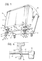
- a bin 10 for example, a refuse bin, comprises a tank-like body 11 closed at the top by a lid 12 and having four feet 13 at the bottom.
- the tank-like body 11 and the feet are preferably, but not necessarily, made of plastics material and produced by moulding.
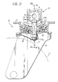
- Each foot 13 has four side faces 13a defining a hole 14 at the bottom which is intended to be closed by a support plate 17 of a castor unit 15 mounted on the foot by means, for example, of screws 16.
- the support plate 17 of the castor unit 15 supports for rotation a yoke 18 which in turn supports a wheel 19, the profile of which is shown partially in chain line in Figure 2.
- a pin 27 is mounted for sliding along an axis A-A coinciding with the axis of rotation of the yoke 18; a plate spring 28 pushes against the lower end 27a of the pin 27 so as to keep its upper end 27b in contact with the active surface 25a of a cam 25 of an actuator mechanism 20.
- a hexagonal hole 26 in the cam 25 is intended to house an operating bar 21 (see Figure 1).
- a rotation of the cam 25 causes the pin 27 to be lowered and the wheel 19 consequently to be locked by the plate spring 28.
- the lowering of the pin 27 simultaneously enables a toothed disc 29 to be lowered, engaging catch projections (not shown) on the sides of the yoke 18 so that its rotation is locked.
- the actuator mechanism 20 of a castor unit 15 is intended to be housed inside a foot 13 and can be operated, in conditions of use, by means of the bar 21 which connects the actuator mechanisms of two adjacent castor units through slots 23 in the sides of the feet, and has a pedal 22 at one end.
- An abutment element 24 is fixed to the bar 21 between the pedal 22 and the actuator mechanism 20 of the first castor unit.
- the bar 21 is also associated with a clamping locking system (not shown in the drawings for reasons of clarity) which enables the castor units to be held in the locked position.
- clamping locking systems are widely known in the art and, since they do not fall within the scope of the present invention, will not be discussed in the following description.
- the abutment element 24 comprises a disc 30, the distance of which from the pedal 22 is predetermined by means, for example, of a tubular spacer 31.
- the abutment element can be fixed to the bar, for example, by means of a spot weld or by any other generally known method.
- the disc-shaped element 30 has a diameter larger than the width of the slot 23, for reasons which will become clear from the following.
- the opposite end 21a of the bar 21 to the end on which the pedal 22 is mounted is conical or, more generally, tapered.
- An annular groove 32 formed near the conical end 21a preferably has a diameter smaller than the circle inscribed in the hexagonal cross-section of the bar 21.
- a rear side 32b of the groove 32, on the left-hand side in Figure 5, is preferably chamfered, whereas the front side 32a forms a right angle with the base of the groove.
- a variant of the bar 21 provides for the formation of a row of grooves 32 spaced apart longitudinally and preferably uniformly, as can be seen in Figure 6.
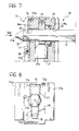
- the cam 25 (see Figures 7 and 8) is enclosed in a casing 33 preferably constituted by two half-shells 33a, 33b of plastics material held together by a substantially U-shaped bent plate 34, preferably of metal.
- a hole 35 for the passage of the bar 21 extends through the casing 33 and the sides 34a, 34b of the plate 34.
- the side 34a which is on the left-hand side in Figure 7 has a transverse slot 36 engaged by the small end portions 37a of a substantially U-shaped wire spring 37 of which the side arms, which are inclined slightly to the vertical, are joined together by a straight portion 37b in turn engaged under a hook 38 formed, for example, by the partial blanking and bending of a portion of the plate 34.
- a corresponding slot and hook may also be provided and formed on the side 34b of the plate 34.
- the wire spring 37 can easily be removed from the position shown in Figures 7 and 8 simply by movement of its side arms towards one another so as to remove the small end portions 37a from the slot 36, and the subsequent removal of the portion 37b from the hook 38.
- a reverse operation enables the wire spring 37 to be repositioned correctly.
- first and second castor units 15 are provided, the actuator mechanism 20 of the second castor unit having the wire spring 37.
- the two castor units are screwed to the respective feet 13 of the bin, account being taken of the fact that the second castor unit which has the wire spring has to be fitted on the foot 13 farthest from the envisaged position of the pedal 22 of the operating bar 21.
- the bar 21 is then inserted through the slots 23 into the hole 35 in the actuator mechanism of the first castor unit and then into that of the second castor unit, until the arms of the wire spring are disposed adjacent the groove 32 and, by engaging therein, lock the translational movement of the bar 21.
- the alternative version of the bar 21 shown in Figure 6, comprising a row of grooves 32 enables the longitudinal position of the bar 21 to be adjusted to take account of the tolerances in the distance between the feet 13.
- the arms of the wire spring 37 can pass from one groove to the next, permitting unidirectional translation of the bar 21 in the direction in which it is inserted.
- the abutment element 24 comes into abutment with the side of the foot 13, it suffices to retract the bar 21 slightly until the wire spring engages in the first groove available. At this point, any further removal of the bar 21 is prevented by the detent constituted by the side 32a of the groove 32.
- all of the actuator mechanisms both of the first and of the second castor unit may have wire springs, possibly mounted on both sides of the plates 34. Naturally, only one wire spring will be used actively for locking the bar 21 by engaging in the groove 32. However, the automatic fitting of the castor units on the feet 13 is thus facilitated since it is no longer necessary to distinguish the first castor unit from the second or to recognize the orientation of the second castor unit relative to the direction of insertion of the bar 21.
- the groove 32 may be formed close to the abutment element 24 so that the active wire spring can be fitted on the first castor unit instead of on the second.
- the wire spring can be removed or positioned easily on the actuator mechanism of a castor unit according to choice is particularly advantageous.
- the castor unit does not differ in its characteristics of use from conventional castor units and, moreover, can quickly be used to form a locking system according to the present invention, if necessary, simply by the addition of the wire spring.
- the wire spring may be replaced by any other resilient element which reacts by bending upon insertion of the bar 21 but which blocks its removal by snap-engaging in the groove 32.
- this function may be performed by a flat spring, or a resilient tongue-like element arranged parallel to the side 34a of the plate 34 with its end connected thereto. The other end of the flat spring partially covers the hole 35 so as to be bent resiliently by the bar 21 until it snaps into the groove 32.
Landscapes
- Engineering & Computer Science (AREA)
- Mechanical Engineering (AREA)
- Chemical & Material Sciences (AREA)
- Combustion & Propulsion (AREA)
- Transportation (AREA)
- Refuse Receptacles (AREA)
- Refuse Collection And Transfer (AREA)
- Lock And Its Accessories (AREA)
- Handcart (AREA)
Claims (8)
- System für das Blockieren von Laufrädern, das zur Montage an beweglichen Körpern, insbesondere von Müllbehältern geeignet ist, mit:wenigstens einem blockierbaren Laufrad (15),wenigstens einem Betätigungsmechanismus (20) für das wenigstens eine Laufrad (15), der ein Gehäuse (33, 34) mit einem Querloch (35) umfasst,einen in dem Loch (35) aufgenommenen, an den Betätigungsmechanismus (20) für die Wirkbetätigung des Mechanismus (20) gekoppelten Betätigungsstab (21) undHaltemittel zum axialen Halten des an die jeweiligen Betätigungsmechanismen (20) gekoppelten Stabes (21), dadurch gekennzeichnet, dass die Haltemittel wenigstens eine an dem Stab (21) gebildete Ringnut (32) und am Gehäuse (33, 34) montierte federnde Eingriffmittel (37) umfassen, die bei Einführung des Stabes (21) in das Querloch (35) federnd verformbar sind, um in die wenigstens eine Nut (32) zum axialen Einklemmen des Stabes (21) relativ zum Gehäuse (33, 34) des Betätigungsmechanismus (20) einzurasten.
- System nach Anspruch 1, dadurch gekennzeichnet, dass der Stab (21) ein kegelförmiges Ende (21a) zum Einführen in das Querloch (35) hat, und dass die wenigstens eine Ringnut (32) nahe an dem kegelförmigen Ende (21a) gebildet ist.
- System nach Anspruch 1 oder Anspruch 2, dadurch gekennzeichnet, dass der Stab eine Mehrzahl von Ringnuten (32) in einem vorgegebenen Abstand hat.
- System nach Anspruch 1, dadurch gekennzeichnet, dass das federnde Eingriffmittel (37) von dem Gehäuse (33, 34) entfernbar ist, wenn der Stab (21) nicht in das Querloch (35) eingeführt ist.
- System nach Anspruch 4, dadurch gekennzeichnet, dass das Querloch (35) zwei gegenüberliegende Löcher im Gehäuse (33, 34) definiert, und das das federnde Eingriffmittel (37) wahlweise an dem zum Betätigungsmechanismus benachbarten und/oder dem anderen der gegenüberliegenden Löcher montierbar ist.
- System nach Anspruch 1, dadurch gekennzeichnet, dass das federnde Eingriffmittel eine Drahtfeder (37) umfasst, die zwei gerade Abschnitte aufweist, die durch den Stab (21) seitwärts gebogen werden, wenn der Stab in das Querloch (35) eingeführt wird, und in die gerade Konfiguration zurückkehren, wenn die Abschnitte in die wenigstens eine Ringnut (32) eingreifen.
- System nach Anspruch 6, dadurch gekennzeichnet, dass die Drahtfeder (37) im Wesentlichen U-förmig ist, dass die geraden Abschnitte an einem Ende durch einen geraden Abschnitt (37b) verbunden sind, der, wenn die Drahtfeder in der montierten Konfiguration ist, an einem Haken (38) verhakt ist, der am Gehäuse (33, 34) gebildet ist, wobei die jeweils anderen Enden der geraden Abschnitte in einen kleinen Endabschnitt (37a) auslaufen, der mit dem Gehäuse (33, 34) im Eingriff ist und sich in dieses durch einen Schlitz (36) erstreckt.
- System nach Anspruch 1, dadurch gekennzeichnet, dass das federnde Eingriffmittel (37) eine flache Feder umfasst.
Applications Claiming Priority (2)
| Application Number | Priority Date | Filing Date | Title |
|---|---|---|---|
| IT95BO000159A IT1280412B1 (it) | 1995-04-11 | 1995-04-11 | Sistema per il bloccaggio di gruppi ruota orientabili montati su corpi mobili, ad esempio contenitori per rifiuti, comprendente una |
| ITBO950159 | 1995-04-11 |
Publications (3)
| Publication Number | Publication Date |
|---|---|
| EP0737596A2 EP0737596A2 (de) | 1996-10-16 |
| EP0737596A3 EP0737596A3 (de) | 1997-10-22 |
| EP0737596B1 true EP0737596B1 (de) | 2000-12-06 |
Family
ID=11340502
Family Applications (1)
| Application Number | Title | Priority Date | Filing Date |
|---|---|---|---|
| EP96200969A Expired - Lifetime EP0737596B1 (de) | 1995-04-11 | 1996-04-09 | Ein System mit Steuerstab für das Blockieren von Laufrädern von beweglichen Körpern, insbesondere von Müllbehältern |
Country Status (5)
| Country | Link |
|---|---|
| EP (1) | EP0737596B1 (de) |
| AT (1) | ATE197935T1 (de) |
| DE (1) | DE69611118T2 (de) |
| ES (1) | ES2153931T3 (de) |
| IT (1) | IT1280412B1 (de) |
Families Citing this family (4)
| Publication number | Priority date | Publication date | Assignee | Title |
|---|---|---|---|---|
| CN107854139B (zh) * | 2017-12-14 | 2023-09-29 | 无锡祥生医疗科技股份有限公司 | 推车式医用超声诊断装置 |
| CN108738760A (zh) * | 2018-07-13 | 2018-11-06 | 芜湖超源力工业设计有限公司 | 一种便捷式切草机 |
| GB2582922B (en) * | 2019-04-08 | 2021-12-15 | Container Components Europe Ltd | A bracket |
| DE202021104420U1 (de) * | 2021-08-18 | 2022-08-19 | Ese World B.V. | Laufrolleneinrichtung für mobile Behälter |
Family Cites Families (5)
| Publication number | Priority date | Publication date | Assignee | Title |
|---|---|---|---|---|
| FR2200123B3 (de) * | 1972-09-22 | 1976-08-06 | Walle Albert Van De | |
| CH570802A5 (en) * | 1973-03-21 | 1975-12-31 | Bremshey Ag | Castor wheel locking system for hospital bed - foot pedal actuated lever system braking all wheels |
| DE8329706U1 (de) * | 1983-10-14 | 1984-01-19 | Haco-Rollen-Vertrieb GmbH & Co KG, 5632 Wermelskirchen | Zentrale feststellvorrichtung fuer an verfahrbaren geraeten, behaeltern od. dgl. zu befestigenden lenk- oder bockrollen |
| DE3602916C2 (de) * | 1985-12-07 | 1994-07-28 | Schulte Soehne Gmbh Co A | Lenkrolle, insbesondere für verfahrbare Krankenbetten |
| EP0631888B1 (de) * | 1993-06-29 | 1998-04-22 | TELLURE ROTA S.p.A. | Feststellbare Lenkrolle zum Stützen eines beweglichen Trägers, insbesondere eines Müllbehälters |
-
1995
- 1995-04-11 IT IT95BO000159A patent/IT1280412B1/it active IP Right Grant
-
1996
- 1996-04-09 DE DE69611118T patent/DE69611118T2/de not_active Expired - Fee Related
- 1996-04-09 EP EP96200969A patent/EP0737596B1/de not_active Expired - Lifetime
- 1996-04-09 AT AT96200969T patent/ATE197935T1/de not_active IP Right Cessation
- 1996-04-09 ES ES96200969T patent/ES2153931T3/es not_active Expired - Lifetime
Non-Patent Citations (2)
| Title |
|---|
| "Industrial Fasteners Handbook", 1976, TRADE & TECHNICAL PRESS LTD., SURREY, ENGLAND * |
| ROBERT O. PAMLEY: "Standard Handbook of Fastening and Joining", 1989, MCGRAW HILL PUBLISHING COMPANY, NEW YORK * |
Also Published As
| Publication number | Publication date |
|---|---|
| ES2153931T3 (es) | 2001-03-16 |
| DE69611118D1 (de) | 2001-01-11 |
| ITBO950159A1 (it) | 1996-10-11 |
| IT1280412B1 (it) | 1998-01-20 |
| ITBO950159A0 (it) | 1995-04-11 |
| EP0737596A2 (de) | 1996-10-16 |
| ATE197935T1 (de) | 2000-12-15 |
| EP0737596A3 (de) | 1997-10-22 |
| DE69611118T2 (de) | 2001-04-05 |
Similar Documents
| Publication | Publication Date | Title |
|---|---|---|
| US5816110A (en) | Locking device for vehicle seats | |
| CN1197722C (zh) | 脚轮 | |
| EP0791483B1 (de) | Richtungsregelung für Lenkrolleneinheit | |
| EP0588409B1 (de) | Verriegelbarer Mechanismus für Schnellentkupplung | |
| US5489107A (en) | Suitcase wheel assembly and retainer | |
| WO1989001884A1 (en) | Arrangement for a vehicle-mounted load-carrier for a cycle | |
| US20060182514A1 (en) | Blind bolt and blind nut | |
| EP0737596B1 (de) | Ein System mit Steuerstab für das Blockieren von Laufrädern von beweglichen Körpern, insbesondere von Müllbehältern | |
| CA2209464A1 (en) | Feeding device for poultry | |
| CA2116605A1 (en) | Cylinder Lock-Key-Combination | |
| EP0574013B1 (de) | Lampen-Befestigungsvorrichtung für Kfz-Scheinwerfer | |
| US5450650A (en) | Pivoting castor with directional locking | |
| EP0143678B1 (de) | Abnehmbare Befestigungsvorrichtung eines Sitzes auf einem Träger, z.B. einem Fahrzeugboden oder Fahrzeugstruktur | |
| US5249879A (en) | Quick release for a bicycle | |
| US4850078A (en) | Adjustable roller assembly for sliding doors | |
| US7441679B1 (en) | One sided adjustable cross rail | |
| EP0764574B1 (de) | Bedienungshebel Trag-/Sperrmechanismus in einer Hebeleinrichtung | |
| US6189488B1 (en) | Waterer for livestock | |
| EP1316657B1 (de) | Zaun mit senkrechten Elementen | |
| US20040012185A1 (en) | Steering column with a locking device | |
| CZ50292A3 (en) | Process of safety belt retractor mounting | |
| EP1747967B1 (de) | Rastvorrichtung und Fahrzeuglenksäule mit einer solchen Vorrichtung | |
| EP0072688A2 (de) | Befestigung für Fahrradlenker | |
| US7347400B2 (en) | Stand for clamping a rod-shaped unit, particularly a Christmas tree | |
| GB2352285A (en) | Clamping device for a steering column |
Legal Events
| Date | Code | Title | Description |
|---|---|---|---|
| PUAI | Public reference made under article 153(3) epc to a published international application that has entered the european phase |
Free format text: ORIGINAL CODE: 0009012 |
|
| AK | Designated contracting states |
Kind code of ref document: A2 Designated state(s): AT CH DE DK ES FR GB GR IT LI NL |
|
| PUAL | Search report despatched |
Free format text: ORIGINAL CODE: 0009013 |
|
| AK | Designated contracting states |
Kind code of ref document: A3 Designated state(s): AT CH DE DK ES FR GB GR IT LI NL |
|
| 17P | Request for examination filed |
Effective date: 19970925 |
|
| 17Q | First examination report despatched |
Effective date: 19990317 |
|
| GRAG | Despatch of communication of intention to grant |
Free format text: ORIGINAL CODE: EPIDOS AGRA |
|
| GRAG | Despatch of communication of intention to grant |
Free format text: ORIGINAL CODE: EPIDOS AGRA |
|
| GRAH | Despatch of communication of intention to grant a patent |
Free format text: ORIGINAL CODE: EPIDOS IGRA |
|
| GRAH | Despatch of communication of intention to grant a patent |
Free format text: ORIGINAL CODE: EPIDOS IGRA |
|
| GRAA | (expected) grant |
Free format text: ORIGINAL CODE: 0009210 |
|
| AK | Designated contracting states |
Kind code of ref document: B1 Designated state(s): AT CH DE DK ES FR GB GR IT LI NL |
|
| PG25 | Lapsed in a contracting state [announced via postgrant information from national office to epo] |
Ref country code: NL Free format text: LAPSE BECAUSE OF FAILURE TO SUBMIT A TRANSLATION OF THE DESCRIPTION OR TO PAY THE FEE WITHIN THE PRESCRIBED TIME-LIMIT Effective date: 20001206 Ref country code: LI Free format text: LAPSE BECAUSE OF FAILURE TO SUBMIT A TRANSLATION OF THE DESCRIPTION OR TO PAY THE FEE WITHIN THE PRESCRIBED TIME-LIMIT Effective date: 20001206 Ref country code: GR Free format text: LAPSE BECAUSE OF NON-PAYMENT OF DUE FEES Effective date: 20001206 Ref country code: CH Free format text: LAPSE BECAUSE OF FAILURE TO SUBMIT A TRANSLATION OF THE DESCRIPTION OR TO PAY THE FEE WITHIN THE PRESCRIBED TIME-LIMIT Effective date: 20001206 |
|
| REF | Corresponds to: |
Ref document number: 197935 Country of ref document: AT Date of ref document: 20001215 Kind code of ref document: T |
|
| REG | Reference to a national code |
Ref country code: CH Ref legal event code: EP |
|
| REF | Corresponds to: |
Ref document number: 69611118 Country of ref document: DE Date of ref document: 20010111 |
|
| ET | Fr: translation filed | ||
| ITF | It: translation for a ep patent filed | ||
| PG25 | Lapsed in a contracting state [announced via postgrant information from national office to epo] |
Ref country code: DK Free format text: LAPSE BECAUSE OF FAILURE TO SUBMIT A TRANSLATION OF THE DESCRIPTION OR TO PAY THE FEE WITHIN THE PRESCRIBED TIME-LIMIT Effective date: 20010306 |
|
| REG | Reference to a national code |
Ref country code: ES Ref legal event code: FG2A Ref document number: 2153931 Country of ref document: ES Kind code of ref document: T3 |
|
| NLV1 | Nl: lapsed or annulled due to failure to fulfill the requirements of art. 29p and 29m of the patents act | ||
| REG | Reference to a national code |
Ref country code: CH Ref legal event code: PL |
|
| PLBE | No opposition filed within time limit |
Free format text: ORIGINAL CODE: 0009261 |
|
| STAA | Information on the status of an ep patent application or granted ep patent |
Free format text: STATUS: NO OPPOSITION FILED WITHIN TIME LIMIT |
|
| 26N | No opposition filed | ||
| REG | Reference to a national code |
Ref country code: GB Ref legal event code: IF02 |
|
| PGFP | Annual fee paid to national office [announced via postgrant information from national office to epo] |
Ref country code: ES Payment date: 20020405 Year of fee payment: 7 |
|
| PGFP | Annual fee paid to national office [announced via postgrant information from national office to epo] |
Ref country code: AT Payment date: 20020409 Year of fee payment: 7 |
|
| PGFP | Annual fee paid to national office [announced via postgrant information from national office to epo] |
Ref country code: GB Payment date: 20020417 Year of fee payment: 7 |
|
| PGFP | Annual fee paid to national office [announced via postgrant information from national office to epo] |
Ref country code: DE Payment date: 20020423 Year of fee payment: 7 |
|
| PGFP | Annual fee paid to national office [announced via postgrant information from national office to epo] |
Ref country code: FR Payment date: 20020430 Year of fee payment: 7 |
|
| PG25 | Lapsed in a contracting state [announced via postgrant information from national office to epo] |
Ref country code: GB Free format text: LAPSE BECAUSE OF NON-PAYMENT OF DUE FEES Effective date: 20030409 Ref country code: AT Free format text: LAPSE BECAUSE OF NON-PAYMENT OF DUE FEES Effective date: 20030409 |
|
| PG25 | Lapsed in a contracting state [announced via postgrant information from national office to epo] |
Ref country code: ES Free format text: LAPSE BECAUSE OF NON-PAYMENT OF DUE FEES Effective date: 20030410 |
|
| PG25 | Lapsed in a contracting state [announced via postgrant information from national office to epo] |
Ref country code: DE Free format text: LAPSE BECAUSE OF NON-PAYMENT OF DUE FEES Effective date: 20031101 |
|
| GBPC | Gb: european patent ceased through non-payment of renewal fee |
Effective date: 20030409 |
|
| PG25 | Lapsed in a contracting state [announced via postgrant information from national office to epo] |
Ref country code: FR Free format text: LAPSE BECAUSE OF NON-PAYMENT OF DUE FEES Effective date: 20031231 |
|
| REG | Reference to a national code |
Ref country code: FR Ref legal event code: ST |
|
| REG | Reference to a national code |
Ref country code: ES Ref legal event code: FD2A Effective date: 20030410 |
|
| PG25 | Lapsed in a contracting state [announced via postgrant information from national office to epo] |
Ref country code: IT Free format text: LAPSE BECAUSE OF NON-PAYMENT OF DUE FEES;WARNING: LAPSES OF ITALIAN PATENTS WITH EFFECTIVE DATE BEFORE 2007 MAY HAVE OCCURRED AT ANY TIME BEFORE 2007. THE CORRECT EFFECTIVE DATE MAY BE DIFFERENT FROM THE ONE RECORDED. Effective date: 20050409 |