EP0736855A2 - Liquid crystal display apparatus control apparatus - Google Patents
Liquid crystal display apparatus control apparatus Download PDFInfo
- Publication number
- EP0736855A2 EP0736855A2 EP96105363A EP96105363A EP0736855A2 EP 0736855 A2 EP0736855 A2 EP 0736855A2 EP 96105363 A EP96105363 A EP 96105363A EP 96105363 A EP96105363 A EP 96105363A EP 0736855 A2 EP0736855 A2 EP 0736855A2
- Authority
- EP
- European Patent Office
- Prior art keywords
- data
- conversion processing
- conversion
- switchover
- display
- Prior art date
- Legal status (The legal status is an assumption and is not a legal conclusion. Google has not performed a legal analysis and makes no representation as to the accuracy of the status listed.)
- Granted
Links
Images


Classifications
-
- G—PHYSICS
- G09—EDUCATION; CRYPTOGRAPHY; DISPLAY; ADVERTISING; SEALS
- G09G—ARRANGEMENTS OR CIRCUITS FOR CONTROL OF INDICATING DEVICES USING STATIC MEANS TO PRESENT VARIABLE INFORMATION
- G09G1/00—Control arrangements or circuits, of interest only in connection with cathode-ray tube indicators; General aspects or details, e.g. selection emphasis on particular characters, dashed line or dotted line generation; Preprocessing of data
- G09G1/06—Control arrangements or circuits, of interest only in connection with cathode-ray tube indicators; General aspects or details, e.g. selection emphasis on particular characters, dashed line or dotted line generation; Preprocessing of data using single beam tubes, e.g. three-dimensional or perspective representation, rotation or translation of display pattern, hidden lines, shadows
- G09G1/14—Control arrangements or circuits, of interest only in connection with cathode-ray tube indicators; General aspects or details, e.g. selection emphasis on particular characters, dashed line or dotted line generation; Preprocessing of data using single beam tubes, e.g. three-dimensional or perspective representation, rotation or translation of display pattern, hidden lines, shadows the beam tracing a pattern independent of the information to be displayed, this latter determining the parts of the pattern rendered respectively visible and invisible
-
- G—PHYSICS
- G09—EDUCATION; CRYPTOGRAPHY; DISPLAY; ADVERTISING; SEALS
- G09G—ARRANGEMENTS OR CIRCUITS FOR CONTROL OF INDICATING DEVICES USING STATIC MEANS TO PRESENT VARIABLE INFORMATION
- G09G5/00—Control arrangements or circuits for visual indicators common to cathode-ray tube indicators and other visual indicators
- G09G5/36—Control arrangements or circuits for visual indicators common to cathode-ray tube indicators and other visual indicators characterised by the display of a graphic pattern, e.g. using an all-points-addressable [APA] memory
- G09G5/39—Control of the bit-mapped memory
- G09G5/399—Control of the bit-mapped memory using two or more bit-mapped memories, the operations of which are switched in time, e.g. ping-pong buffers
-
- G—PHYSICS
- G09—EDUCATION; CRYPTOGRAPHY; DISPLAY; ADVERTISING; SEALS
- G09G—ARRANGEMENTS OR CIRCUITS FOR CONTROL OF INDICATING DEVICES USING STATIC MEANS TO PRESENT VARIABLE INFORMATION
- G09G3/00—Control arrangements or circuits, of interest only in connection with visual indicators other than cathode-ray tubes
- G09G3/20—Control arrangements or circuits, of interest only in connection with visual indicators other than cathode-ray tubes for presentation of an assembly of a number of characters, e.g. a page, by composing the assembly by combination of individual elements arranged in a matrix no fixed position being assigned to or needed to be assigned to the individual characters or partial characters
- G09G3/34—Control arrangements or circuits, of interest only in connection with visual indicators other than cathode-ray tubes for presentation of an assembly of a number of characters, e.g. a page, by composing the assembly by combination of individual elements arranged in a matrix no fixed position being assigned to or needed to be assigned to the individual characters or partial characters by control of light from an independent source
- G09G3/36—Control arrangements or circuits, of interest only in connection with visual indicators other than cathode-ray tubes for presentation of an assembly of a number of characters, e.g. a page, by composing the assembly by combination of individual elements arranged in a matrix no fixed position being assigned to or needed to be assigned to the individual characters or partial characters by control of light from an independent source using liquid crystals
- G09G3/3611—Control of matrices with row and column drivers
- G09G3/3622—Control of matrices with row and column drivers using a passive matrix
- G09G3/3629—Control of matrices with row and column drivers using a passive matrix using liquid crystals having memory effects, e.g. ferroelectric liquid crystals
-
- G—PHYSICS
- G09—EDUCATION; CRYPTOGRAPHY; DISPLAY; ADVERTISING; SEALS
- G09G—ARRANGEMENTS OR CIRCUITS FOR CONTROL OF INDICATING DEVICES USING STATIC MEANS TO PRESENT VARIABLE INFORMATION
- G09G2310/00—Command of the display device
- G09G2310/04—Partial updating of the display screen
-
- G—PHYSICS
- G09—EDUCATION; CRYPTOGRAPHY; DISPLAY; ADVERTISING; SEALS
- G09G—ARRANGEMENTS OR CIRCUITS FOR CONTROL OF INDICATING DEVICES USING STATIC MEANS TO PRESENT VARIABLE INFORMATION
- G09G3/00—Control arrangements or circuits, of interest only in connection with visual indicators other than cathode-ray tubes
- G09G3/20—Control arrangements or circuits, of interest only in connection with visual indicators other than cathode-ray tubes for presentation of an assembly of a number of characters, e.g. a page, by composing the assembly by combination of individual elements arranged in a matrix no fixed position being assigned to or needed to be assigned to the individual characters or partial characters
- G09G3/2007—Display of intermediate tones
- G09G3/2044—Display of intermediate tones using dithering
- G09G3/2051—Display of intermediate tones using dithering with use of a spatial dither pattern
-
- G—PHYSICS
- G09—EDUCATION; CRYPTOGRAPHY; DISPLAY; ADVERTISING; SEALS
- G09G—ARRANGEMENTS OR CIRCUITS FOR CONTROL OF INDICATING DEVICES USING STATIC MEANS TO PRESENT VARIABLE INFORMATION
- G09G3/00—Control arrangements or circuits, of interest only in connection with visual indicators other than cathode-ray tubes
- G09G3/20—Control arrangements or circuits, of interest only in connection with visual indicators other than cathode-ray tubes for presentation of an assembly of a number of characters, e.g. a page, by composing the assembly by combination of individual elements arranged in a matrix no fixed position being assigned to or needed to be assigned to the individual characters or partial characters
- G09G3/2007—Display of intermediate tones
- G09G3/2059—Display of intermediate tones using error diffusion
Definitions
- This invention relates to a display control apparatus and method, and a display apparatus using the display control apparatus.
- a CRT video output signal from a host computer is transferred to a CRT display or a liquid crystal display such as a TFT synchronized with the transfer speed and scanning of all the scan lines is made for each frame, in accordance with an interlaced scanning method.
- a CRT display or a liquid crystal display such as a TFT synchronized with the transfer speed and scanning of all the scan lines is made for each frame, in accordance with an interlaced scanning method.
- a so-called partial rewriting method is employed to update display of only scan line(s) where motion has been detected. This seemingly ensures a frame frequency corresponding to the CRT video output signal.
- a ⁇ converter is provided at an arbitrary position in an image processing system as a data converter for input data.
- a motion detector is necessary for detecting a line where motion has occurred. Even if data conversion processing such as ⁇ conversion is changed ( ⁇ value for ⁇ conversion is changed) while drawing is performed on data that needs continuous partial rewriting, only the line where motion has been detected by the motion detector is rewritten in the partial-rewrite processing. This partial rewriting produces a frame period where line data before the ⁇ -value switchover and data after the ⁇ -value switchover are mixedly displayed. Accordingly, display status is degraded.
- the motion detector is provided after the ⁇ converter, the operation of the ⁇ converter itself might be regarded as a part of the motion.
- the ⁇ converter converts image data, the amount of change with respect to the input image data changes after the ⁇ conversion, thus causing degradation of motion-detection efficiency.
- the present invention has been made in consideration of the above problems, and has its object to provide a display control apparatus and method and display apparatus using the display control apparatus which, if the input-data conversion is switched during display control by partial-rewrite processing, prevents mixed display of data before the switchover of input-data conversion and data after the switchover of input-data conversion, within one frame.
- Another object of the present invention is to enable stable detection of a changed position in partial-rewrite processing, without receiving any influence due to input-data conversion.
- Another object of the present invention is to provide a display control apparatus and method corresponding to various video signals and display devices, by adopting ⁇ -value switchable ⁇ conversion as a variable input-data conversion processing.
- Another object of the present invention is to prevent occurrence of inappropriate data upon switching input-data conversion processing so as to realize switchover of conversion processing without displaying unnatural images.
- Another object of the present invention is to enable manual switching of the input-data conversion processing so that a user can arbitrarily set a conversion processing while observing a display screen.
- another object of the present invention is to enable switchover of input-data conversion processing based on an external signal.
- a user need not perform manual operation such as setting of conversion processing.
- appropriate ⁇ conversion is automatically made by inputting a ⁇ value used by a video interface attached to an external device which supplies input data, and setting the conversion processing so as to perform appropriate ⁇ conversion based on the ⁇ value, thus offloading user's operation.
- another object of the present invention is to enable changing input-data conversion processing based on a signal from a connected display device so as to easily set conversion processing corresponding to the display device. For example, an appropriate ⁇ value can be automatically set even when the display device is changed, by inputting a ⁇ value, appropriate to the connected display device, for switching the ⁇ value for the input-data conversion.
- Another object of the present invention is to provide a display apparatus having a display device for displaying data outputted from a display control apparatus according to the present invention.
- Another object of the present invention is to perform display control of an FLC panel which has display-status maintainability and which is appropriate to partial rewrite control.
- ⁇ conversion is adopted as input-data conversion, and a case where ⁇ -value switchover for the ⁇ conversion is performed while partial rewriting of display data is performed by output device will be described.
- display control is made such that all the data for at least one frame are newly written after ⁇ -value switchover, regardless of the detection of a change of display contents between frames by detection device. This prevents inconvenience of mixed display of display data before ⁇ -value switchover and display data after the ⁇ -value switchover.
- the input to the ⁇ converter and that to the motion detector device are the same. This improves motion detection efficiency.
- Fig. 1 is a block diagram showing the construction of an information processing apparatus according to a first embodiment of the present invention.
- reference numeral 100 denotes a host unit 100 such as a personal computer.
- the host unit 100 outputs an RGB analog video signal 23 under the control of its internal CPU.
- Numeral 101 denotes a display device interface (I/F) which converts the input RGB analog video signal 23 into a signal appropriate to be displayed by a display device 11.
- an FLC display is used as the display device 11.
- the display device I/F 101 has an A/D converter 102 for converting the input RGB analog video signal 23 into digital input data 1.
- Numeral 103 denotes an image processor which performs processing such as ⁇ correction and partial-rewrite processing on the input data 1, and generates output data 10 suitable to the display device 11.
- the display device 11 performs image display in accordance with the output data 11.
- Numeral 104 denotes an operation panel for various operation-inputs by a user.
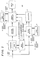
- Fig. 2 is a block diagram showing the construction of the image processor 103 in Fig. 1.
- Numeral 1 denotes input data, which is RGB-input digital data obtained by A/D-converting a CRT video input signal; and 2, a ⁇ converter having a SRAM 2a for storing a look-up table for ⁇ conversion (hereinafter referred to as " ⁇ -conversion table").
- the ⁇ converter 2 can rewrite the ⁇ -conversion table stored in the SRAM 2a using inputs from a microprocessor 6.
- the ⁇ converter 2 converts the input data 1 into address data of the SRAM 2a, reads data after the ⁇ conversion corresponding to the input data 1, and outputs the read data to a halftone processor 3.
- the halftone processor 3 performs pseudo full-color processing using conversion of the ⁇ output into appropriate color space to the FLC display, error diffusion or dither processing.
- the conversion of the ⁇ output to appropriate color space to the FLC display is, e.g., in a case where image input data of the halftone processor has color information which the FLC display cannot display, the data is converted to the closest color data around a boundary of the color space which can be displayed by the FLC display (so-called color-space clipping processing).
- the converted image data is stored into one of two buffers of a DRAM (hereinafter referred to as "double buffer") 5 by a memory controller 4.
- the input data 1 inputted into the ⁇ converter 2 is also inputted into a motion detector 7 which detects change of motion in each line by comparing Nth frame data with previous (N-1)th frame data.
- the (N-1)th frame data is stored in one of two buffers of a DRAM (hereinafter referred to as "double buffer") 8, to be referred to in comparison with the Nth frame.
- Numeral 9 denotes a line selector which determines line data to be read from one of the buffers of the double buffer 5 by the memory controller 4, in accordance with the amount of motion in each line detected by the motion detector 7.
- Numeral 10 denotes output data comprising of a line address of the selected line and data in a format suitable to the display device (FLC display in this embodiment) 11.
- Numeral 14 denotes a ⁇ -value switchover request which is generated as a signal indicative of ⁇ -value switchover code, and supplied to a microprocessor 6.
- the ⁇ conversion is performed on the input data 1, in accordance with the initial ⁇ -conversion table set in the SRAM 2a of the ⁇ converter 2.
- the processed data is passed through the halftone processor 3, and stored into a buffer of the double buffer 5 under the control of the memory controller 4.
- the memory controller 4 generates a buffer switchover address 16 for controlling the writing into the double buffer 5.
- Figs. 3A and 3B respectively show the construction of the double buffer 5.
- the Nth frame data is stored into a buffer A20.
- the (N-1)th frame data is in a buffer B21 in standby status for reading for necessary line(s).
- the value of the switchover address bit is "1”
- switching of the buffers are made as shown in Fig. 3B.
- the buffer A20 is in standby status for reading, and (N+1)th frame data is written into the buffer B21.
- the memory controller controls writing/reading to/from the double buffer 5 such that writing and reading are switched by each frame data at the respective buffers.
- the motion detector 7 which performs processing based on the same frame period as that of writing of the input data 1 from the ⁇ converter 2 into the double buffer 5, is connected to the double buffer 8 having the same structure as that of the double buffer 5.
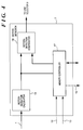
- Fig. 4 shows the construction of the motion detector 7.
- numeral 19 denotes a motion-detection calculator which interprets the signature (feature) of motion by each line with respect to the previous frame of the input data 1. More specifically, each line data is converted into signature data comprising of average motion correlation data and instant motion correlation data, and the signature data is stored one buffer of the double buffer 8 under the control of the memory controller 17.
- the signature data is also inputted into a motion-detection comparator 18.
- the motion-detection comparator 18 compares the signature data inputted from the motion-detection calculator 19 with signature data of the previous frame data read by the memory controller 17 from the double buffer 8. In a case where the signature of the current processed frame data has been changed from that of the previous frame data, it is determined that motion has occurred. This series of processings is performed on all the scan lines, to detect motion in each scan line within one frame. The obtained motion detection information is transferred to a line selector 9.
- the memory controller 17 controls the double buffer 8 with a buffer switchover address 15, similar to the memory controller 4.
- the read/write control on the double buffer 8 and that on the double buffer 5 are synchronized so as to maintain coherency.
- To maintain coherency means to handle the same read/write frame at an instant, in the image processing system including the halftone processor and the image processing system including the motion detector.
- the line selector 9 determines lines to be directed to partial-rewrite processing, based on the motion detection information in each line within one frame, inputted from the motion detector 7, and forwards the determination result to the memory controller 4 as line address information to be transferred to the display device 11.
- the memory controller 4 reads data from the buffer in reading-standby status of the double buffer 5, based on the address information. Thus, the memory controller 4 transfers the partial-rewrite address(es) and corresponding display data to the display device 11.
- the microprocessor 6 always monitors the status of the line selector 9 via a state bus 19, prepared for a case where the range of line address outputted by the line selector 9 exceeds a range of drawing for one frame in the display device 11 within a predetermined period. If the above status is found, the microprocessor 6 issues a hold requirement 13 to the memory controllers 14 and 17 so as to suspend the processing on the next frame until the processing on the current frame has been completed.
- the normal partial-rewrite processing is performed in the sequence as described above.
- ⁇ -value switchover requirement 14 when the ⁇ -value switchover requirement 14 is transferred to the microprocessor 6, the microprocessor 6 recognizes the requirement and enters into ⁇ -value switchover mode.
- the microprocessor 6 writes a ⁇ -conversion table corresponding to the requirement, from a plurality of ⁇ -conversion tables stored in its internal ROM, into the SRAM 2a of the ⁇ converter 2.
- process timing is adjusted by issuance of the hold requirement 13 as described above.
- FIG. 6 is a block diagram showing the construction of the information processing apparatus according to the second embodiment.
- the present system construction is briefly divided into the host unit 100, a display device interface (I/F) 101a which receives the RGB analog video signal 23 from the host unit 100, and the display device 11 connected to the display device I/F 101a.
- I/F display device interface
- the display device I/F 101a comprises a system having the A/D converter 102 and the image processor 103 provided after the A/D converter 102 (Fig. 2).
- the ⁇ -value switchover requirement 14 is transferred to the microprocessor 6 by a user switch (operation panel 104) of the display device I/F 101.
- data transferred by RS232C transmission from the host unit 100 is received via a serial interface (I/F) 105, and inputted into the image processor 103, thus signals other than the video signal can be transferred from the host unit 100 to the display device I/F 101a.
- This construction enables to transfer ⁇ -value designation which differs by each graphic card of the host unit 100, from the host unit 100 to the display device I/F 101a.
- the microprocessor 6 in the image processor 103 selects an inverse ⁇ -conversion table suitable to the display device 11, based on the ⁇ -value designation sent from the host unit 100. Note that the inverse ⁇ -conversion table appropriate to the input ⁇ -value designation is selected in accordance with a correspondence table pre-registered in the ROM (not shown) of the image processor 103. Then, the selected ⁇ -conversion table is written into the SRAM 2a of the ⁇ converter 2.
- a user does not have to manually adjust a ⁇ value for each graphic card, and the host unit 100 automatically control the ⁇ value to attain appropriate ⁇ conversion.
- the ⁇ -value switchover process sequence during partial-rewrite processing is performed in the same manner as that of the first embodiment.
- the host unit 100 detects the ⁇ value of an attached graphic card and informs the display device I/F 101a of the detected ⁇ value at predetermined timing.
- the predetermined timing means that detection is made at a point in time where the power is turned on, at a point in time where a ⁇ -value notification requirement is received from the display device I/F 101a or the like.
- the acquisition of ⁇ value by the host unit 100 may be made by, e.g., preparing a table showing the correspondence between various graphic cards and ⁇ values in the host computer, judging the type of an attached graphic card and referring to the table. Further, this type of table may be prepared on the display device I/F 101a side and receive information on the type of a graphic card from the host unit 100.
- ⁇ -value switchover is made by manual operation at the operation panel 104.
- ⁇ -conversion table is automatically switched in accordance with a graphic card or the like by data communication (based on RS232C communication in the second embodiment) from the host unit 100.
- data communication based on RS232C communication in the second embodiment
- automatic adjustment of the ⁇ value can be made when the display device 11 is exchanged with a different type display device.
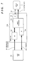
- Fig. 7 is a block diagram showing the construction of the information processing apparatus according to the third embodiment.
- Numeral 106 denotes an interface which receives a signal 25 designating a ⁇ value corresponding to the display device 11 from the display device 11.
- the interface 106 comprises, e.g., an RS2332C interface, for serial communication.
- the serial communication function between the image processor 103 and the display device 11 enables to transfer a ⁇ -value designation signal from the display device 11 upon activation of the image processing apparatus.
- the microprocessor 6 selects an inverse ⁇ -conversion value appropriate to the graphic card attached to the host unit 100, based on the ⁇ value sent from the host unit 100 and the ⁇ value sent from the display device 11.
- ⁇ -conversion tables corresponding to various display devices and inverse ⁇ -conversion tables corresponding to various graphic cards are registered in advance as reference tables in the ROM (not shown) in the image processor 103. In this manner, an appropriate ⁇ -conversion table is written into the SRAM 2a of the ⁇ converter 2.
- tables for inverse ⁇ conversion and tables for ⁇ conversion may be independently prepared for converting input data, otherwise, integrated conversion tables, each including an inverse ⁇ -conversion table and a ⁇ -conversion table, corresponding to combinations of an inverse ⁇ value and a ⁇ value may be prepared for converting input data.
- a user's manual adjustment of ⁇ value that differs based on the type of a graphic card and a display device can be offloaded. That is, automatic ⁇ -conversion table selection can be made such that ⁇ conversion appropriate to a currently-connected display device and a graphic card attached thereto is selected. Note that the process sequence of ⁇ -value switchover during partial-rewrite processing is the same as that of the first embodiment.
- the display device 11 informs a display device I/F 101b of a ⁇ value appropriate to the display panel at predetermined timing.
- the predetermined timing means that informing is made at a point in time where the power is turned on, at a point in time where a ⁇ -value notification requirement is received from the display device I/F 101b or the like.
- a table showing the correspondence between various display devices and ⁇ values may be provided in the display device I/F 101b so that information on the type of the display device 11 is received from the display device 11, and a ⁇ value is selected in accordance with the received information and the correspondence table.
- partial-rewrite control is performed by the ⁇ converter and the motion detector serially connected to each other with respect to input data.
- the partial-rewrite control if the ⁇ value is switched over, all the lines of display data after the ⁇ -value switchover are rewritten. This facilitates data updating for the whole frame image after the ⁇ -value switchover, and prevents the inconvenience that display data before the ⁇ -value switchover and display data after the ⁇ -value switchover are mixedly exist in the same frame.
- the motion detector performs detection on input data before ⁇ conversion, the detection is not influenced by the ⁇ -conversion, thus degradation of motion-detection efficiency can be prevented.
- the microprocessor prohibits storing of image data for one frame when the ⁇ value is switched, which prevents writing of inappropriate data, caused by the ⁇ -value switchover, into the buffer.
- the microprocessor prohibits storing of image data for one frame when the ⁇ value is switched, which prevents writing of inappropriate data, caused by the ⁇ -value switchover, into the buffer.
- ⁇ -value switchover on the display device side can be made from the host unit side (the second embodiment), and means for obtaining ⁇ -value information by each type of display device is provided (the third embodiment), a user's manual adjustment of an inverse ⁇ value and a ⁇ value, in correspondence with the ⁇ value of a graphic card attached to the host unit and the characteristic of the display device, can be offloaded. This provides a user-friendly color-management environment.
- an FLC display is employed as the display device 11, however the display device 11 is not limited to the FLC display. Any display device is acceptable so far as it has a display-frame frequency at a slower drawing speed than an input-frame frequency.
- the mixed display of data before the input-data conversion switchover and data after the input-data conversion switchover within one frame can be prevented.
- the object of the present invention can be also achieved by providing a storage medium storing program codes for performing the aforesaid processes to a system or an apparatus, reading the program codes with a computer (e.g., CPU, MPU) of the system or apparatus from the storage medium, then executing the program.
- a computer e.g., CPU, MPU
- the program codes read from the storage medium realize the functions according to the embodiments, and the storage medium storing the program codes constitutes the invention.
- the storage medium such as a floppy disk, a hard disk, an optical disk, a magneto-optical disk, CD-ROM, CD-R, a magnetic tape, a non-volatile type memory card, and ROM can be used for providing the program codes.
- the present invention includes a case where an OS (operating system) or the like working on the computer performs a part or entire processes in accordance with designations of the program codes and realizes functions according to the above embodiments.
- the present invention also includes a case where, after the program codes read from the storage medium are written in a function expansion card which is inserted into the computer or in a memory provided in a function expansion unit which is connected to the computer, CPU or the like contained in the function expansion card or unit performs a part or entire process in accordance with designations of the program codes and realizes functions of the above embodiments.
- a motion detector detects a line where change of image data has occurred, and a line selector selects the line where display is to be updated, based on the motion detection.
- a ⁇ converter performs ⁇ conversion on the input data with a predetermined ⁇ value and obtains converted data.
- a memory controller partially updates display on a display device with display data of the line selected by the line selector, among display data suitable to the display device generated based on the converted data. If the ⁇ value of the ⁇ converter is switched, the display data generated based on the converted data obtained from ⁇ conversion after the switchover of the ⁇ value display on the display device is updated for at least one frame.
Abstract
Description
- This invention relates to a display control apparatus and method, and a display apparatus using the display control apparatus.
- Generally, a CRT video output signal from a host computer is transferred to a CRT display or a liquid crystal display such as a TFT synchronized with the transfer speed and scanning of all the scan lines is made for each frame, in accordance with an interlaced scanning method. In such display device, even when a γ value is rewritten, the processing is always completed within one frame, thus data display can be performed with no trouble.
- In a slow-response FLC (ferroelectric liquid crystal) display or the like where only a frequency component lower than the frame frequency component can be drawn, to make up with the transfer speed, a so-called partial rewriting method is employed to update display of only scan line(s) where motion has been detected. This seemingly ensures a frame frequency corresponding to the CRT video output signal. Generally, a γ converter is provided at an arbitrary position in an image processing system as a data converter for input data.
- However, in the system as described above, where a CRT video output signal is converted into a signal appropriate to an FLC display having maintainability in the liquid crystal itself, if γ-value switchover function based on user's selection is provided, the following problem occurs.
- To perform the partial rewriting as described above, a motion detector is necessary for detecting a line where motion has occurred. Even if data conversion processing such as γ conversion is changed (γ value for γ conversion is changed) while drawing is performed on data that needs continuous partial rewriting, only the line where motion has been detected by the motion detector is rewritten in the partial-rewrite processing. This partial rewriting produces a frame period where line data before the γ-value switchover and data after the γ-value switchover are mixedly displayed. Accordingly, display status is degraded.
- Further, if the motion detector is provided after the γ converter, the operation of the γ converter itself might be regarded as a part of the motion. When the γ converter converts image data, the amount of change with respect to the input image data changes after the γ conversion, thus causing degradation of motion-detection efficiency.
- The present invention has been made in consideration of the above problems, and has its object to provide a display control apparatus and method and display apparatus using the display control apparatus which, if the input-data conversion is switched during display control by partial-rewrite processing, prevents mixed display of data before the switchover of input-data conversion and data after the switchover of input-data conversion, within one frame.
- Further, another object of the present invention is to enable stable detection of a changed position in partial-rewrite processing, without receiving any influence due to input-data conversion.
- Further, another object of the present invention is to provide a display control apparatus and method corresponding to various video signals and display devices, by adopting γ-value switchable γ conversion as a variable input-data conversion processing.
- Further, another object of the present invention is to prevent occurrence of inappropriate data upon switching input-data conversion processing so as to realize switchover of conversion processing without displaying unnatural images.
- Further, another object of the present invention is to enable manual switching of the input-data conversion processing so that a user can arbitrarily set a conversion processing while observing a display screen.
- Further, another object of the present invention is to enable switchover of input-data conversion processing based on an external signal. As the conversion processing is switched by the external signal, a user need not perform manual operation such as setting of conversion processing. For example, appropriate γ conversion is automatically made by inputting a γ value used by a video interface attached to an external device which supplies input data, and setting the conversion processing so as to perform appropriate γ conversion based on the γ value, thus offloading user's operation.
- Further, another object of the present invention is to enable changing input-data conversion processing based on a signal from a connected display device so as to easily set conversion processing corresponding to the display device. For example, an appropriate γ value can be automatically set even when the display device is changed, by inputting a γ value, appropriate to the connected display device, for switching the γ value for the input-data conversion.
- Further, another object of the present invention is to provide a display apparatus having a display device for displaying data outputted from a display control apparatus according to the present invention.
- Further, another object of the present invention is to perform display control of an FLC panel which has display-status maintainability and which is appropriate to partial rewrite control.
- Other features and advantages of the present invention will be apparent from the following description taken in conjunction with the accompanying drawings, in which like reference characters designate the same name or similar parts throughout the figures thereof.
- The accompanying drawings, which are incorporated in and constitute a part of the specification, illustrate embodiments of the invention and, together with the description, serve to explain the principles of the invention.
- Fig. 1 is a block diagram showing the construction of an information processing apparatus according to a first embodiment;
- Fig. 2 is a block diagram showing the construction of an
image processor 103 in Fig. 1; - Figs. 3A and 3B are block diagrams respectively showing the construction of a
double buffer 5 in Fig. 2; - Fig. 4 is a block diagram showing the construction of a
motion detector 7 in Fig. 2; - Fig. 5 is an explanatory view showing a γ-value switchover procedure according to the first embodiment;
- Fig. 6 is a block diagram showing the construction of the information processing apparatus according to a second embodiment; and
- Fig. 7 is a block diagram showing the construction of the information processing apparatus according to a third embodiment.
- Preferred embodiments of the present invention will now be described in detail in accordance with the accompanying drawings.
- In the following embodiments, γ conversion is adopted as input-data conversion, and a case where γ-value switchover for the γ conversion is performed while partial rewriting of display data is performed by output device will be described. In this case, display control is made such that all the data for at least one frame are newly written after γ-value switchover, regardless of the detection of a change of display contents between frames by detection device. This prevents inconvenience of mixed display of display data before γ-value switchover and display data after the γ-value switchover.
- Further, according to the following embodiments, the input to the γ converter and that to the motion detector device are the same. This improves motion detection efficiency.
- Fig. 1 is a block diagram showing the construction of an information processing apparatus according to a first embodiment of the present invention. In Fig. 1,
reference numeral 100 denotes ahost unit 100 such as a personal computer. Thehost unit 100 outputs an RGBanalog video signal 23 under the control of its internal CPU. Numeral 101 denotes a display device interface (I/F) which converts the input RGBanalog video signal 23 into a signal appropriate to be displayed by adisplay device 11. In this embodiment, an FLC display is used as thedisplay device 11. The display device I/F 101 has an A/D converter 102 for converting the input RGBanalog video signal 23 intodigital input data 1. Numeral 103 denotes an image processor which performs processing such as γ correction and partial-rewrite processing on theinput data 1, and generatesoutput data 10 suitable to thedisplay device 11. Thedisplay device 11 performs image display in accordance with theoutput data 11. Numeral 104 denotes an operation panel for various operation-inputs by a user. - Fig. 2 is a block diagram showing the construction of the
image processor 103 in Fig. 1. - Numeral 1 denotes input data, which is RGB-input digital data obtained by A/D-converting a CRT video input signal; and 2, a γ converter having a
SRAM 2a for storing a look-up table for γ conversion (hereinafter referred to as "γ-conversion table"). Theγ converter 2 can rewrite the γ-conversion table stored in the SRAM 2a using inputs from amicroprocessor 6. Theγ converter 2 converts theinput data 1 into address data of theSRAM 2a, reads data after the γ conversion corresponding to theinput data 1, and outputs the read data to ahalftone processor 3. - The
halftone processor 3 performs pseudo full-color processing using conversion of the γ output into appropriate color space to the FLC display, error diffusion or dither processing. The conversion of the γ output to appropriate color space to the FLC display is, e.g., in a case where image input data of the halftone processor has color information which the FLC display cannot display, the data is converted to the closest color data around a boundary of the color space which can be displayed by the FLC display (so-called color-space clipping processing). The converted image data is stored into one of two buffers of a DRAM (hereinafter referred to as "double buffer") 5 by amemory controller 4. - On the other hand, the
input data 1 inputted into theγ converter 2 is also inputted into amotion detector 7 which detects change of motion in each line by comparing Nth frame data with previous (N-1)th frame data. At this time, the (N-1)th frame data is stored in one of two buffers of a DRAM (hereinafter referred to as "double buffer") 8, to be referred to in comparison with the Nth frame. - Numeral 9 denotes a line selector which determines line data to be read from one of the buffers of the
double buffer 5 by thememory controller 4, in accordance with the amount of motion in each line detected by themotion detector 7.Numeral 10 denotes output data comprising of a line address of the selected line and data in a format suitable to the display device (FLC display in this embodiment) 11.Numeral 14 denotes a γ-value switchover request which is generated as a signal indicative of γ-value switchover code, and supplied to amicroprocessor 6. - Next, image processing according to the present embodiment having the above construction will be described.
- First, normal partial-rewrite processing will be described. The γ conversion is performed on the
input data 1, in accordance with the initial γ-conversion table set in theSRAM 2a of theγ converter 2. The processed data is passed through thehalftone processor 3, and stored into a buffer of thedouble buffer 5 under the control of thememory controller 4. At this time, thememory controller 4 generates abuffer switchover address 16 for controlling the writing into thedouble buffer 5. - Figs. 3A and 3B respectively show the construction of the
double buffer 5. As shown in Fig. 3A, when the value of a switchover address bit is "0", the Nth frame data is stored into a buffer A20. On the other hand, the (N-1)th frame data is in a buffer B21 in standby status for reading for necessary line(s). When a new frame data is written, the value of the switchover address bit is "1", and switching of the buffers are made as shown in Fig. 3B. The buffer A20 is in standby status for reading, and (N+1)th frame data is written into the buffer B21. Thus, the memory controller controls writing/reading to/from thedouble buffer 5 such that writing and reading are switched by each frame data at the respective buffers. - On the other hand, the
motion detector 7, which performs processing based on the same frame period as that of writing of theinput data 1 from theγ converter 2 into thedouble buffer 5, is connected to thedouble buffer 8 having the same structure as that of thedouble buffer 5. Fig. 4 shows the construction of themotion detector 7. - In Fig. 4, numeral 19 denotes a motion-detection calculator which interprets the signature (feature) of motion by each line with respect to the previous frame of the
input data 1. More specifically, each line data is converted into signature data comprising of average motion correlation data and instant motion correlation data, and the signature data is stored one buffer of thedouble buffer 8 under the control of thememory controller 17. - On the other hand, the signature data is also inputted into a motion-
detection comparator 18. The motion-detection comparator 18 compares the signature data inputted from the motion-detection calculator 19 with signature data of the previous frame data read by thememory controller 17 from thedouble buffer 8. In a case where the signature of the current processed frame data has been changed from that of the previous frame data, it is determined that motion has occurred. This series of processings is performed on all the scan lines, to detect motion in each scan line within one frame. The obtained motion detection information is transferred to aline selector 9. - Further, the
memory controller 17 controls thedouble buffer 8 with abuffer switchover address 15, similar to thememory controller 4. The read/write control on thedouble buffer 8 and that on thedouble buffer 5 are synchronized so as to maintain coherency. To maintain coherency means to handle the same read/write frame at an instant, in the image processing system including the halftone processor and the image processing system including the motion detector. - The
line selector 9 determines lines to be directed to partial-rewrite processing, based on the motion detection information in each line within one frame, inputted from themotion detector 7, and forwards the determination result to thememory controller 4 as line address information to be transferred to thedisplay device 11. Thememory controller 4 reads data from the buffer in reading-standby status of thedouble buffer 5, based on the address information. Thus, thememory controller 4 transfers the partial-rewrite address(es) and corresponding display data to thedisplay device 11. - Note that the
microprocessor 6 always monitors the status of theline selector 9 via astate bus 19, prepared for a case where the range of line address outputted by theline selector 9 exceeds a range of drawing for one frame in thedisplay device 11 within a predetermined period. If the above status is found, themicroprocessor 6 issues ahold requirement 13 to thememory controllers - The normal partial-rewrite processing is performed in the sequence as described above.
- Next, a case where γ-value switchover occurring during the above partial-rewrite processing will be described. In Fig. 2, when the γ-
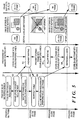
value switchover requirement 14 is transferred to themicroprocessor 6, themicroprocessor 6 recognizes the requirement and enters into γ-value switchover mode. Themicroprocessor 6 writes a γ-conversion table corresponding to the requirement, from a plurality of γ-conversion tables stored in its internal ROM, into theSRAM 2a of theγ converter 2. - The γ-value switchover algorithm according to the present embodiment (the substantial hardware operations in the partial-rewrite processing before γ-value switchover is as described above) will be described in detail with reference to Fig. 5 showing the γ-value switchover processing procedure.
- (a) Current processed frame: Nth frame
The frame displayed on thedisplay device 11 is the previous (N-1)th frame, and partial-rewrite processing is performed on only line(s) where motion has been detected. The Nth frame data before γ-value switchover is stored in one of the buffer selected for writing of thedouble buffer 5. If themicroprocessor 6 detects the γ-value switchover requirement 14 (S1), it issues thehold requirement 13 shown in Fig. 2 to thememory controllers 4 and 17 (S2) as a frame-store prohibit requirement.
Thememory controllers double buffers microprocessor 6 at this time is in waiting status until the frame end of the Nth frame data (the rest period of processing the Nth frame data), and performs other processes (S3). Accordingly, the image data of the Nth frame is all written into thedouble buffer 5 and the signature data of the Nth frame data is all written into thedouble buffer 8. - (b) Current processed frame: (N+1)th frame
Themicroprocessor 6 updates the contents of theSRAM 2a of theγ converter 2 in accordance with the γ-value switchover requirement 14 (S5). As the writing to thedouble buffers microprocessor 6 is ignored. The frame displayed on thedisplay device 11 is the Nth frame, and partial-rewrite processing is performed on only line(s) where motion (change) has been detected during the processing on the Nth frame. Also, themicroprocessor 6 generates an all-line refresh requirement signal 12 (Fig. 2) (S6) during this frame period. The all-linerefresh requirement signal 12 is transferred to thememory controller 4, which begins preparation for reading data for all the lines from one buffer in reading-standby status of thedouble buffer 5. - (c) Current processed frame: (N+2)th frame
The prohibition of writing to thedouble buffers memory controllers double buffer 5. In this frame period, the Nth frame data is maintained on thedisplay device 11 utilizing the feature of the FLC display, display-status maintainability. - (d) Current processed frame: (N+3)th frame
In this frame, in accordance with the all-line refresh requirement issued at step S6, the data of the all lines are transferred to the display device 11 (S8). In a case where this processing is not performed, if line(s) where motion (change) has been detected is a part of one frame during processing of the (N+2) frame, the Nth frame data before γ conversion and the (N+2)th frame data after the γ conversion are mixed in one frame, thus causing inappropriate display on thedisplay device 11. To avoid such inconvenience, if the γ value has been switched, all the lines are refreshed so as to prevent inappropriate display of data before and after the γ-value switchover. In this manner, whenever γ-value switchover is performed during partial-rewrite processing, all the lines are refreshed, so that drawing on the display device can be done without inconvenience. - Note that if time necessary for updating display content by this all-line refreshment is longer than time for processing the next frame, process timing is adjusted by issuance of the
hold requirement 13 as described above. - Further, in the construction of the present embodiment, as both the
γ converter 2 and themotion detector 7 input thesame input data 1, the problem of degradation of motion-detection efficiency due to γ-value switchover can be solved. - In this embodiment, another method for transferring the γ-
value switchover requirement 14 to themicroprocessor 6 will be described. Fig. 6 is a block diagram showing the construction of the information processing apparatus according to the second embodiment. In Fig. 6, the present system construction is briefly divided into thehost unit 100, a display device interface (I/F) 101a which receives the RGBanalog video signal 23 from thehost unit 100, and thedisplay device 11 connected to the display device I/F 101a. - The display device I/
F 101a comprises a system having the A/D converter 102 and theimage processor 103 provided after the A/D converter 102 (Fig. 2). - In the first embodiment, the γ-
value switchover requirement 14 is transferred to themicroprocessor 6 by a user switch (operation panel 104) of the display device I/F 101. In the second embodiment, data transferred by RS232C transmission from thehost unit 100 is received via a serial interface (I/F) 105, and inputted into theimage processor 103, thus signals other than the video signal can be transferred from thehost unit 100 to the display device I/F 101a. - This construction enables to transfer γ-value designation which differs by each graphic card of the
host unit 100, from thehost unit 100 to the display device I/F 101a. Themicroprocessor 6 in theimage processor 103 selects an inverse γ-conversion table suitable to thedisplay device 11, based on the γ-value designation sent from thehost unit 100. Note that the inverse γ-conversion table appropriate to the input γ-value designation is selected in accordance with a correspondence table pre-registered in the ROM (not shown) of theimage processor 103. Then, the selected γ-conversion table is written into theSRAM 2a of theγ converter 2. - According to the second embodiment, a user does not have to manually adjust a γ value for each graphic card, and the
host unit 100 automatically control the γ value to attain appropriate γ conversion. Note that the γ-value switchover process sequence during partial-rewrite processing is performed in the same manner as that of the first embodiment. - Note that as it is apparent from the above description, the
host unit 100 detects the γ value of an attached graphic card and informs the display device I/F 101a of the detected γ value at predetermined timing. The predetermined timing means that detection is made at a point in time where the power is turned on, at a point in time where a γ-value notification requirement is received from the display device I/F 101a or the like. - The acquisition of γ value by the
host unit 100 may be made by, e.g., preparing a table showing the correspondence between various graphic cards and γ values in the host computer, judging the type of an attached graphic card and referring to the table. Further, this type of table may be prepared on the display device I/F 101a side and receive information on the type of a graphic card from thehost unit 100. - In the first embodiment, γ-value switchover is made by manual operation at the
operation panel 104. In the second embodiment, γ-conversion table is automatically switched in accordance with a graphic card or the like by data communication (based on RS232C communication in the second embodiment) from thehost unit 100. In this embodiment, in addition to the direct control from the host unit side in the second embodiment, automatic adjustment of the γ value can be made when thedisplay device 11 is exchanged with a different type display device. - Fig. 7 is a block diagram showing the construction of the information processing apparatus according to the third embodiment.
Numeral 106 denotes an interface which receives asignal 25 designating a γ value corresponding to thedisplay device 11 from thedisplay device 11. In this embodiment, theinterface 106 comprises, e.g., an RS2332C interface, for serial communication. The serial communication function between theimage processor 103 and thedisplay device 11 enables to transfer a γ-value designation signal from thedisplay device 11 upon activation of the image processing apparatus. - On the other hand, the
microprocessor 6 selects an inverse γ-conversion value appropriate to the graphic card attached to thehost unit 100, based on the γ value sent from thehost unit 100 and the γ value sent from thedisplay device 11. Note that γ-conversion tables corresponding to various display devices and inverse γ-conversion tables corresponding to various graphic cards are registered in advance as reference tables in the ROM (not shown) in theimage processor 103. In this manner, an appropriate γ-conversion table is written into theSRAM 2a of theγ converter 2. - Regarding the γ-conversion tables, tables for inverse γ conversion and tables for γ conversion may be independently prepared for converting input data, otherwise, integrated conversion tables, each including an inverse γ-conversion table and a γ-conversion table, corresponding to combinations of an inverse γ value and a γ value may be prepared for converting input data.
- According to the third embodiment, a user's manual adjustment of γ value that differs based on the type of a graphic card and a display device can be offloaded. That is, automatic γ-conversion table selection can be made such that γ conversion appropriate to a currently-connected display device and a graphic card attached thereto is selected. Note that the process sequence of γ-value switchover during partial-rewrite processing is the same as that of the first embodiment.
- Note that as it is apparent from the above description, the
display device 11 informs a display device I/F 101b of a γ value appropriate to the display panel at predetermined timing. The predetermined timing means that informing is made at a point in time where the power is turned on, at a point in time where a γ-value notification requirement is received from the display device I/F 101b or the like. - Further, a table showing the correspondence between various display devices and γ values may be provided in the display device I/
F 101b so that information on the type of thedisplay device 11 is received from thedisplay device 11, and a γ value is selected in accordance with the received information and the correspondence table. - As described above, according to the embodiments, partial-rewrite control is performed by the γ converter and the motion detector serially connected to each other with respect to input data.
During the partial-rewrite control, if the γ value is switched over, all the lines of display data after the γ-value switchover are rewritten. This facilitates data updating for the whole frame image after the γ-value switchover, and prevents the inconvenience that display data before the γ-value switchover and display data after the γ-value switchover are mixedly exist in the same frame. Further, as the motion detector performs detection on input data before γ conversion, the detection is not influenced by the γ-conversion, thus degradation of motion-detection efficiency can be prevented. - Further, according to the embodiments, the microprocessor prohibits storing of image data for one frame when the γ value is switched, which prevents writing of inappropriate data, caused by the γ-value switchover, into the buffer. Thus disturbance of drawing on the display device upon the γ-value switchover can be prevented.
- Further, γ-value switchover on the display device side can be made from the host unit side (the second embodiment), and means for obtaining γ-value information by each type of display device is provided (the third embodiment), a user's manual adjustment of an inverse γ value and a γ value, in correspondence with the γ value of a graphic card attached to the host unit and the characteristic of the display device, can be offloaded. This provides a user-friendly color-management environment.
- Further, in the above embodiments, an FLC display is employed as the
display device 11, however thedisplay device 11 is not limited to the FLC display. Any display device is acceptable so far as it has a display-frame frequency at a slower drawing speed than an input-frame frequency. - As described above, according to the present invention, in a case where input-data conversion is switched while display control by partial-rewrite processing is performed, the mixed display of data before the input-data conversion switchover and data after the input-data conversion switchover within one frame can be prevented.
- Note that the object of the present invention can be also achieved by providing a storage medium storing program codes for performing the aforesaid processes to a system or an apparatus, reading the program codes with a computer (e.g., CPU, MPU) of the system or apparatus from the storage medium, then executing the program.
- In this case, the program codes read from the storage medium realize the functions according to the embodiments, and the storage medium storing the program codes constitutes the invention.
- Further, the storage medium, such as a floppy disk, a hard disk, an optical disk, a magneto-optical disk, CD-ROM, CD-R, a magnetic tape, a non-volatile type memory card, and ROM can be used for providing the program codes.
- Furthermore, besides aforesaid functions according to the above embodiments are realized by executing the program codes which are read by a computer, the present invention includes a case where an OS (operating system) or the like working on the computer performs a part or entire processes in accordance with designations of the program codes and realizes functions according to the above embodiments.
- Furthermore, the present invention also includes a case where, after the program codes read from the storage medium are written in a function expansion card which is inserted into the computer or in a memory provided in a function expansion unit which is connected to the computer, CPU or the like contained in the function expansion card or unit performs a part or entire process in accordance with designations of the program codes and realizes functions of the above embodiments.
- As many apparently widely different embodiments of the present invention can be made without departing from the spirit and scope thereof, it is to be understood that the invention is not limited to the specific embodiments thereof except as defined in the claims.
- A motion detector detects a line where change of image data has occurred, and a line selector selects the line where display is to be updated, based on the motion detection. A γ converter performs γ conversion on the input data with a predetermined γ value and obtains converted data. A memory controller partially updates display on a display device with display data of the line selected by the line selector, among display data suitable to the display device generated based on the converted data. If the γ value of the γ converter is switched, the display data generated based on the converted data obtained from γ conversion after the switchover of the γ value display on the display device is updated for at least one frame.
Claims (36)
- A display control apparatus which inputs frame-unit image data and performs display control, characterized by comprising:conversion means (2) for performing a predetermined conversion processing on the input image data to obtain converted data;detection means (7, 8) for detecting a change between frames of the input image data;first output means (4) for outputting data to partially update display based on the change detected by said detection means and the converted data obtained by said conversion means;switching means (6) for switching the conversion processing of said conversion means; andsecond output means (4) for, if said switching means switches the conversion processing of said conversion means, outputting data consisting of converted data obtained from conversion processing switched by said switching means, for at least one frame.
- The display control apparatus according to claim 1, wherein the predetermined conversion processing of said conversion means is γ conversion.
- The display control apparatus according to claim 2, wherein said switching means switches a γ value used in the γ conversion.
- The display control apparatus according to claim 1, further comprising prohibition means (4) for, if said switching means switches the conversion processing, prohibiting use of image data, inputted during at least a frame period in which switchover of the conversion processing has been made.
- The display control apparatus according to claim 4, wherein if said switch means switches the conversion processing, said prohibition means prohibits said detection means from detecting the change during at least a frame period in which the switchover of the conversion processing has been made.
- The display control apparatus according to claim 4, wherein if said switch means switches the conversion processing, said prohibition means prohibits output of data for updating using the image data inputted during at least a frame period in which the switchover of the conversion processing has been made.
- The display control apparatus according to claim 4, further comprising converted-data storage means (4, 5) for storing the converted data obtained by said conversion means, as data to be used by said first output means, for at least one frame,
wherein said prohibition means prohibits said converted-data storage means from storing the converted data during at least a frame period in which the switchover of the conversion processing has been made. - The display control apparatus according to claim 4, further comprising data storage means (8) for storing data based on the input image data, as data to be used by said detection means, for at least one frame,
wherein said prohibition means prohibits said data storage means from storing the data during at least a frame period in which the switchover of the conversion processing has been made. - The display control apparatus according to claim 1, wherein switchover of the conversion processing by said switching means is made by manual operation.
- The display control apparatus according to claim 1, further comprising input means (105) for inputting a signal designating conversion processing to be used by said conversion means, from an external device,
wherein switchover of the conversion processing by said switching means is made based on the signal inputted by said input means. - The display control apparatus according to claim 1, further comprising input means (106) for inputting a signal designating conversion processing to be used by said conversion means, from a display device to be controlled by said display control apparatus,
wherein switchover of the conversion processing by said switching means is made based on the signal inputted by said input means. - The display control apparatus according to claim 1, wherein said switching means performs switchover of the conversion processing during a frame period subsequent to a frame in which switching instruction has been detected.
- A display apparatus which inputs frame-unit image data and displays an image, characterized by comprising:conversion means (2) for performing a predetermined conversion processing on the input image data to obtain converted data;detection means (7, 8) for detecting a change between frames of the input image data;first output means (4) for outputting data to partially update display based on the change detected by said detection means and the converted data obtained by said conversion means;switching means (6) for switching the conversion processing of said conversion means;second output means (4) for, if said switching means switches the conversion processing of said conversion means, outputting data consisting of converted data obtained from conversion processing switched by said switching means, for at least one frame; anddisplay means (11) for displaying an image based on data outputted by said first output means and said second output means.
- The display apparatus according to claim 13, wherein the predetermined conversion processing of said conversion means is γ conversion.
- The display apparatus according to claim 13, wherein said switching means switches a γ value used in the γ conversion.
- The display apparatus according to claim 13, further comprising prohibition means (4) for, if said switching means switches the conversion processing, prohibiting use of image data, inputted during at least a frame period in which switchover of the conversion processing has been made.
- The display apparatus according to claim 16, wherein if said switch means switches the conversion processing, said prohibition means prohibits said detection means from detecting the change during at least a frame period in which the switchover of the conversion processing has been made.
- The display apparatus according to claim 16, wherein if said switch means switches the conversion processing, said prohibition means prohibits output of data for updating using the image data inputted during at least a frame period in which the switchover of the conversion processing has been made.
- The display apparatus according to claim 16, further comprising converted-data storage means (4, 5) for storing the converted data obtained by said conversion means, as data to be used by said first output means, for at least one frame,
wherein said prohibition means prohibits said converted-data storage means from storing the converted data during at least a frame period in which the switchover of the conversion processing has been made. - The display apparatus according to claim 16, further comprising data storage means (8) for storing data based on the input image data, as data to be used by said detection means, for at least one frame,
wherein said prohibition means prohibits said data storage means from storing the data during at least a frame period in which the switchover of the conversion processing has been made. - The display apparatus according to claim 13, wherein switchover of the conversion processing by said switching means is made by manual operation.
- The display apparatus according to claim 13, further comprising input means (105) for inputting a signal designating conversion processing to be used by said conversion means, from an external device,
wherein switchover of the conversion processing by said switching means is made based on the signal inputted by said input means. - The display apparatus according to claim 13, wherein said switching means performs switchover of the conversion processing during a frame period subsequent to a frame in which switching instruction has been detected.
- The display apparatus according to claim 13, wherein said display means comprises a ferroelectric liquid crystal display panel.
- A display method for inputting frame-unit image data and performing display control, characterized by comprising:a conversion step (2) of performing a predetermined conversion processing on the input image data to obtain converted data;a detection step (7, 8) of detecting a change between frames of the input image data;a first output step (4) of outputting data to partially update display based on the change detected at said detection step and the converted data obtained at said conversion step;a switching step (S1, S5) of switching the conversion processing at said conversion step; anda second output step (S8) of, if the conversion processing at said conversion step is switched at said switching step, outputting data consisting of converted data obtained from conversion processing switched at said switching step, for at least one frame.
- The display control method according to claim 25, wherein the predetermined conversion processing at said conversion step is γ conversion.
- The display control method according to claim 25, wherein a γ value used in the γ conversion is switched at said switching step.
- The display control method according to claim 25, further comprising a prohibition step (S4) of, if the conversion processing is switched at said switching step, prohibiting use of image data, inputted during at least a frame period in which switchover of the conversion processing has been made.
- The display control method according to claim 28, wherein if the conversion processing is switched at said switching step, detection of the change at said detection step is prohibited at said prohibition step, during at least a frame period in which the switchover of the conversion processing has been made.
- The display control method according to claim 28, wherein if the conversion processing is switched at said switching step, output of data for updating using the image data, inputted during at least a frame period in which the switchover of the conversion processing has been made, is prohibited at said prohibition step.
- The display control method according to claim 28, further comprising a converted-data storage step of storing the converted data obtained at said conversion step, as data to be used at said first output step, for at least one frame,
wherein storing the converted data at said converted-data storage step is prohibited at said prohibition step, during at least a frame period in which the switchover of the conversion processing has been made. - The display control method according to claim 28, further comprising a data storage step of storing data based on the input image data, as data to be used at said detection step, for at least one frame,
wherein storing the data at said data storage step is prohibited at said prohibition step, during at least a frame period in which the switchover of the conversion processing has been made. - The display control method according to claim 25, wherein switchover of the conversion processing at said switching step is made by manual operation.
- The display control method according to claim 25, further comprising an input step (106) of inputting a signal designating conversion processing to be used at said conversion step, from an external device,
wherein switchover of the conversion processing at said switching step is made based on the signal inputted at said input step. - The display control method according to claim 25, further comprising an input step (106) of inputting a signal designating conversion processing to be used at said conversion step, from a display device to be controlled by said display control method,
wherein switchover of the conversion processing at said switching step is made based on the signal inputted at said input step. - The display control method according to claim 25, wherein at said switching step, switchover of the conversion processing is performed during a frame period subsequent to a frame in which switching instruction has been detected.
Applications Claiming Priority (3)
| Application Number | Priority Date | Filing Date | Title |
|---|---|---|---|
| JP8041295 | 1995-04-05 | ||
| JP7080412A JPH08278486A (en) | 1995-04-05 | 1995-04-05 | Device and method for controlling display and display device |
| JP80412/95 | 1995-04-05 |
Publications (3)
| Publication Number | Publication Date |
|---|---|
| EP0736855A2 true EP0736855A2 (en) | 1996-10-09 |
| EP0736855A3 EP0736855A3 (en) | 1997-05-28 |
| EP0736855B1 EP0736855B1 (en) | 2004-03-17 |
Family
ID=13717589
Family Applications (1)
| Application Number | Title | Priority Date | Filing Date |
|---|---|---|---|
| EP96105363A Expired - Lifetime EP0736855B1 (en) | 1995-04-05 | 1996-04-03 | Control apparatus for liquid crystal display |
Country Status (5)
| Country | Link |
|---|---|
| US (1) | US5815135A (en) |
| EP (1) | EP0736855B1 (en) |
| JP (1) | JPH08278486A (en) |
| KR (1) | KR100247316B1 (en) |
| DE (1) | DE69631854T2 (en) |
Cited By (2)
| Publication number | Priority date | Publication date | Assignee | Title |
|---|---|---|---|---|
| EP1244091A3 (en) * | 2001-03-23 | 2007-05-23 | Microsoft Corporation | Methods and systems for displaying animated graphics on a computing device |
| US7239324B2 (en) | 2001-03-23 | 2007-07-03 | Microsoft Corporation | Methods and systems for merging graphics for display on a computing device |
Families Citing this family (30)
| Publication number | Priority date | Publication date | Assignee | Title |
|---|---|---|---|---|
| US8352400B2 (en) | 1991-12-23 | 2013-01-08 | Hoffberg Steven M | Adaptive pattern recognition based controller apparatus and method and human-factored interface therefore |
| US10361802B1 (en) | 1999-02-01 | 2019-07-23 | Blanding Hovenweep, Llc | Adaptive pattern recognition based control system and method |
| JP3624982B2 (en) * | 1995-12-21 | 2005-03-02 | ソニー株式会社 | Image control apparatus and method |
| JPH11143379A (en) * | 1997-09-03 | 1999-05-28 | Semiconductor Energy Lab Co Ltd | Semiconductor display device correcting system and its method |
| US6538675B2 (en) | 1998-04-17 | 2003-03-25 | Canon Kabushiki Kaisha | Display control apparatus and display control system for switching control of two position indication marks |
| US7148909B2 (en) * | 1998-05-27 | 2006-12-12 | Canon Kabushiki Kaisha | Image display system capable of displaying and scaling images on plurality of image sources and display control method therefor |
| US6473088B1 (en) | 1998-06-16 | 2002-10-29 | Canon Kabushiki Kaisha | System for displaying multiple images and display method therefor |
| US6441870B1 (en) * | 1998-12-22 | 2002-08-27 | Gateway, Inc. | Automatic gamma correction for multiple video sources |
| JP4508330B2 (en) | 1999-01-25 | 2010-07-21 | キヤノン株式会社 | Display device |
| US7966078B2 (en) | 1999-02-01 | 2011-06-21 | Steven Hoffberg | Network media appliance system and method |
| US6313813B1 (en) | 1999-10-21 | 2001-11-06 | Sony Corporation | Single horizontal scan range CRT monitor |
| JP2001195053A (en) * | 2000-01-06 | 2001-07-19 | Internatl Business Mach Corp <Ibm> | Monitor system, liquid crystal display device, display device, and image display method of display device |
| JP4541482B2 (en) * | 2000-02-29 | 2010-09-08 | キヤノン株式会社 | Image processing apparatus and image processing method |
| US6816138B2 (en) * | 2000-04-27 | 2004-11-09 | Manning Ventures, Inc. | Graphic controller for active matrix addressed bistable reflective cholesteric displays |
| EP1193978A1 (en) * | 2000-09-29 | 2002-04-03 | Koninklijke Philips Electronics N.V. | Display refresh method |
| KR100815893B1 (en) * | 2001-09-12 | 2008-03-24 | 엘지.필립스 엘시디 주식회사 | Method and Apparatus For Driving Liquid Crystal Display |
| KR100769174B1 (en) * | 2001-09-17 | 2007-10-23 | 엘지.필립스 엘시디 주식회사 | Method and Apparatus For Driving Liquid Crystal Display |
| KR20030073390A (en) | 2002-03-11 | 2003-09-19 | 삼성전자주식회사 | A liquid crystal display for improving dynamic contrast and a method for generating gamma voltages for the liquid crystal display |
| US7272497B2 (en) * | 2003-03-24 | 2007-09-18 | Fuji Jukogyo Kabushiki Kaisha | Vehicle navigation system with multi-use display |
| JP4577549B2 (en) * | 2004-01-22 | 2010-11-10 | ソニー株式会社 | Image display device |
| TWI287770B (en) * | 2004-03-09 | 2007-10-01 | Novatek Microelectronics Corp | Color managing structure and method for panel display apparauts |
| JP4154422B2 (en) * | 2004-12-15 | 2008-09-24 | キヤノン株式会社 | Image display device |
| JP4154423B2 (en) * | 2004-12-17 | 2008-09-24 | キヤノン株式会社 | Image display device |
| KR101167515B1 (en) | 2004-12-30 | 2012-07-20 | 엘지디스플레이 주식회사 | Driving method for display panel and display apparatus |
| JP2007274198A (en) * | 2006-03-30 | 2007-10-18 | Kyocera Corp | Organic el display device and driving method therefor |
| US7903047B2 (en) * | 2006-04-17 | 2011-03-08 | Qualcomm Mems Technologies, Inc. | Mode indicator for interferometric modulator displays |
| WO2008117784A1 (en) * | 2007-03-26 | 2008-10-02 | Nec Corporation | Portable phone terminal, image display controlling method, program thereof, and program recording medium |
| JP5343785B2 (en) * | 2009-09-17 | 2013-11-13 | ソニー株式会社 | Image signal processing device, transmission device, image signal processing method, program, and image signal processing system |
| KR20140046844A (en) | 2012-10-11 | 2014-04-21 | 삼성전자주식회사 | Display system for reducing power consumption and method for driving thereof |
| CN109360523B (en) * | 2018-12-12 | 2020-11-27 | 惠科股份有限公司 | Display panel driving method and driving device and display device |
Citations (1)
| Publication number | Priority date | Publication date | Assignee | Title |
|---|---|---|---|---|
| EP0608053A2 (en) * | 1993-01-11 | 1994-07-27 | Canon Kabushiki Kaisha | Colour display system |
Family Cites Families (3)
| Publication number | Priority date | Publication date | Assignee | Title |
|---|---|---|---|---|
| JP2584871B2 (en) * | 1989-08-31 | 1997-02-26 | キヤノン株式会社 | Display device |
| US5420603A (en) * | 1991-02-20 | 1995-05-30 | Canon Kabushiki Kaisha | Display apparatus |
| EP0608056B1 (en) * | 1993-01-11 | 1998-07-29 | Canon Kabushiki Kaisha | Display line dispatcher apparatus |
-
1995
- 1995-04-05 JP JP7080412A patent/JPH08278486A/en not_active Withdrawn
-
1996
- 1996-03-29 US US08/625,069 patent/US5815135A/en not_active Expired - Lifetime
- 1996-04-03 EP EP96105363A patent/EP0736855B1/en not_active Expired - Lifetime
- 1996-04-03 DE DE69631854T patent/DE69631854T2/en not_active Expired - Lifetime
- 1996-04-04 KR KR1019960010236A patent/KR100247316B1/en not_active IP Right Cessation
Patent Citations (1)
| Publication number | Priority date | Publication date | Assignee | Title |
|---|---|---|---|---|
| EP0608053A2 (en) * | 1993-01-11 | 1994-07-27 | Canon Kabushiki Kaisha | Colour display system |
Cited By (4)
| Publication number | Priority date | Publication date | Assignee | Title |
|---|---|---|---|---|
| EP1244091A3 (en) * | 2001-03-23 | 2007-05-23 | Microsoft Corporation | Methods and systems for displaying animated graphics on a computing device |
| US7239324B2 (en) | 2001-03-23 | 2007-07-03 | Microsoft Corporation | Methods and systems for merging graphics for display on a computing device |
| US7315308B2 (en) | 2001-03-23 | 2008-01-01 | Microsoft Corporation | Methods and system for merging graphics for display on a computing device |
| US7439981B2 (en) | 2001-03-23 | 2008-10-21 | Microsoft Corporation | Methods and systems for displaying animated graphics on a computing device |
Also Published As
| Publication number | Publication date |
|---|---|
| EP0736855A3 (en) | 1997-05-28 |
| KR960038716A (en) | 1996-11-21 |
| US5815135A (en) | 1998-09-29 |
| DE69631854D1 (en) | 2004-04-22 |
| JPH08278486A (en) | 1996-10-22 |
| EP0736855B1 (en) | 2004-03-17 |
| KR100247316B1 (en) | 2000-03-15 |
| DE69631854T2 (en) | 2005-02-03 |
Similar Documents
| Publication | Publication Date | Title |
|---|---|---|
| US5815135A (en) | Display control apparatus | |
| EP0725380A1 (en) | Display control method for display apparatus having maintainability of display-status function and display control system | |
| US6078317A (en) | Display device, and display control method and apparatus therefor | |
| US5764201A (en) | Multiplexed yuv-movie pixel path for driving dual displays | |
| US7202848B2 (en) | Liquid crystal display control device | |
| US6421094B1 (en) | HDTV video display processor | |
| US5977946A (en) | Multi-window apparatus | |
| US6140996A (en) | Display control apparatus | |
| US6661414B1 (en) | Display system with a displaying apparatus that transmits control information | |
| US5499327A (en) | Multi-window system which can overlay-display a dynamic image in a specific window | |
| JP3286529B2 (en) | Display device | |
| US4961071A (en) | Apparatus for receipt and display of raster scan imagery signals in relocatable windows on a video monitor | |
| US5880702A (en) | Display control apparatus and method | |
| JPH05127608A (en) | Liquid crystal display device | |
| EP0343636B1 (en) | Apparatus for receiving character multiplex broadcasting | |
| US6747656B2 (en) | Image processing apparatus and method of the same, and display apparatus using the image processing apparatus | |
| US7336286B2 (en) | Method of and an apparatus for processing images | |
| US6128032A (en) | Method for scrolling a video signal in an internet set top box | |
| JP2000078395A (en) | Scanner system, server device and host equipment | |
| JP2001013940A (en) | Display controller and method therefor | |
| JP4029692B2 (en) | Display device | |
| JPH05344328A (en) | Printing device | |
| US20040085336A1 (en) | System and method for video control in a computer | |
| JPH04337877A (en) | Picture display device | |
| JPH08123376A (en) | Display control method, device therefor and, display device |
Legal Events
| Date | Code | Title | Description |
|---|---|---|---|
| PUAI | Public reference made under article 153(3) epc to a published international application that has entered the european phase |
Free format text: ORIGINAL CODE: 0009012 |
|
| AK | Designated contracting states |
Kind code of ref document: A2 Designated state(s): DE FR GB IT NL |
|
| PUAL | Search report despatched |
Free format text: ORIGINAL CODE: 0009013 |
|
| AK | Designated contracting states |
Kind code of ref document: A3 Designated state(s): DE FR GB IT NL |
|
| 17P | Request for examination filed |
Effective date: 19971014 |
|
| 17Q | First examination report despatched |
Effective date: 20020903 |
|
| GRAP | Despatch of communication of intention to grant a patent |
Free format text: ORIGINAL CODE: EPIDOSNIGR1 |
|
| RTI1 | Title (correction) |
Free format text: CONTROL APPARATUS FOR LIQUID CRYSTAL DISPLAY |
|
| GRAS | Grant fee paid |
Free format text: ORIGINAL CODE: EPIDOSNIGR3 |
|
| GRAA | (expected) grant |
Free format text: ORIGINAL CODE: 0009210 |
|
| AK | Designated contracting states |
Kind code of ref document: B1 Designated state(s): DE FR GB IT NL |
|
| PG25 | Lapsed in a contracting state [announced via postgrant information from national office to epo] |
Ref country code: NL Free format text: LAPSE BECAUSE OF FAILURE TO SUBMIT A TRANSLATION OF THE DESCRIPTION OR TO PAY THE FEE WITHIN THE PRESCRIBED TIME-LIMIT Effective date: 20040317 Ref country code: IT Free format text: LAPSE BECAUSE OF FAILURE TO SUBMIT A TRANSLATION OF THE DESCRIPTION OR TO PAY THE FEE WITHIN THE PRE;WARNING: LAPSES OF ITALIAN PATENTS WITH EFFECTIVE DATE BEFORE 2007 MAY HAVE OCCURRED AT ANY TIME BEFORE 2007. THE CORRECT EFFECTIVE DATE MAY BE DIFFERENT FROM THE ONE RECORDED.SCRIBED TIME-LIMIT Effective date: 20040317 |
|
| REG | Reference to a national code |
Ref country code: GB Ref legal event code: FG4D |
|
| REF | Corresponds to: |
Ref document number: 69631854 Country of ref document: DE Date of ref document: 20040422 Kind code of ref document: P |
|
| NLV1 | Nl: lapsed or annulled due to failure to fulfill the requirements of art. 29p and 29m of the patents act | ||
| ET | Fr: translation filed | ||
| PLBE | No opposition filed within time limit |
Free format text: ORIGINAL CODE: 0009261 |
|
| STAA | Information on the status of an ep patent application or granted ep patent |
Free format text: STATUS: NO OPPOSITION FILED WITHIN TIME LIMIT |
|
| 26N | No opposition filed |
Effective date: 20041220 |
|
| PGFP | Annual fee paid to national office [announced via postgrant information from national office to epo] |
Ref country code: GB Payment date: 20140414 Year of fee payment: 19 |
|
| PGFP | Annual fee paid to national office [announced via postgrant information from national office to epo] |
Ref country code: DE Payment date: 20140430 Year of fee payment: 19 Ref country code: FR Payment date: 20140428 Year of fee payment: 19 |
|
| REG | Reference to a national code |
Ref country code: DE Ref legal event code: R119 Ref document number: 69631854 Country of ref document: DE |
|
| GBPC | Gb: european patent ceased through non-payment of renewal fee |
Effective date: 20150403 |
|
| PG25 | Lapsed in a contracting state [announced via postgrant information from national office to epo] |
Ref country code: DE Free format text: LAPSE BECAUSE OF NON-PAYMENT OF DUE FEES Effective date: 20151103 Ref country code: GB Free format text: LAPSE BECAUSE OF NON-PAYMENT OF DUE FEES Effective date: 20150403 |
|
| REG | Reference to a national code |
Ref country code: FR Ref legal event code: ST Effective date: 20151231 |
|
| PG25 | Lapsed in a contracting state [announced via postgrant information from national office to epo] |
Ref country code: FR Free format text: LAPSE BECAUSE OF NON-PAYMENT OF DUE FEES Effective date: 20150430 |