EP0736795A1 - Compact rear projection device - Google Patents
Compact rear projection device Download PDFInfo
- Publication number
- EP0736795A1 EP0736795A1 EP96400712A EP96400712A EP0736795A1 EP 0736795 A1 EP0736795 A1 EP 0736795A1 EP 96400712 A EP96400712 A EP 96400712A EP 96400712 A EP96400712 A EP 96400712A EP 0736795 A1 EP0736795 A1 EP 0736795A1
- Authority
- EP
- European Patent Office
- Prior art keywords
- image
- component
- projection device
- rear projection
- screen
- Prior art date
- Legal status (The legal status is an assumption and is not a legal conclusion. Google has not performed a legal analysis and makes no representation as to the accuracy of the status listed.)
- Granted
Links
Images


Classifications
-
- G—PHYSICS
- G03—PHOTOGRAPHY; CINEMATOGRAPHY; ANALOGOUS TECHNIQUES USING WAVES OTHER THAN OPTICAL WAVES; ELECTROGRAPHY; HOLOGRAPHY
- G03B—APPARATUS OR ARRANGEMENTS FOR TAKING PHOTOGRAPHS OR FOR PROJECTING OR VIEWING THEM; APPARATUS OR ARRANGEMENTS EMPLOYING ANALOGOUS TECHNIQUES USING WAVES OTHER THAN OPTICAL WAVES; ACCESSORIES THEREFOR
- G03B21/00—Projectors or projection-type viewers; Accessories therefor
- G03B21/10—Projectors with built-in or built-on screen
-
- H—ELECTRICITY
- H04—ELECTRIC COMMUNICATION TECHNIQUE
- H04N—PICTORIAL COMMUNICATION, e.g. TELEVISION
- H04N5/00—Details of television systems
- H04N5/74—Projection arrangements for image reproduction, e.g. using eidophor
- H04N5/7408—Direct viewing projectors, e.g. an image displayed on a video CRT or LCD display being projected on a screen
Definitions
- the field of the invention is that of visualization which is evolving in particular towards the presentation of high resolution images having increasingly large dimensions typically greater than 1m diagonal.
- the invention relates to a new type of overhead projector, more compact, making it possible to envisage in the short term the production of flat screens intended for viewing large images.
- FIG. 1 The image from the image generator (GI) via a projection optic (OP) is returned using a main mirror M p towards the screen, the mirror M p being typically oriented by an angle ⁇ of 45 ° relative to the screen and making it possible to reduce by half the size between image generator and screen compared to a frontal projection of the image on the screen.
- GI image generator
- OP projection optic
- the invention provides a rear projection device in which the angle between the screen (E) and the deflecting mirror M p can be reduced thanks to the presence of an optical component of the type "mixer" located near the plane on which the final image is formed.
- the subject of the invention is a rear projection device comprising a system (GI) for generating a small image, a projection optic transforming the small image into a large image (I 1 ) and a screen (E) on which the final image (I f ) is formed, characterized in that it comprises at least one deflection component (MR) and an optical mixing component (OM) near the screen (E ), capable of reflecting in the vicinity of an average incidence ⁇ 1 almost all of the image (I 1 ) in an image (I 2 ) and capable of transmitting in the vicinity of an average incidence ⁇ o almost all of the image (I f ) created by reflection of the image (I 2 ) on the component (MR).
- GI system
- GI system
- GI for generating a small image
- a projection optic transforming the small image into a large image (I 1 ) and a screen (E) on which the final image (I f ) is formed
- MR deflection component
- OM optical mixing component
- optical mixing component is characterized by the fact that it is used locally both in transmission and in reflection.
- the two optical components (OM) and (MR) respectively of mixing and return are thus associated to reduce the size of the rear projection device.
- the image generator (GI) is an assembly associating a liquid crystal modulator and a lighting source, having a smaller geometric extent than that coming from cathode ray tubes.
- the overhead projector according to the invention can advantageously comprise two optical return components (OM) 1 and (OM) r so as to further reduce the size of the device by confining the optical path of the light flux, that is to say by making him do several "back and forth". More specifically, this device comprises a component (OM) 1 located near the screen (E), a component (OM) r located between the component (OM) 1 and a conventional optical reference component (MR), the component (OM) r being capable of transmitting almost all of the image (I 1 ) and almost all of the image (I 2 ) created by reflection of the image (I 1 ) on the component (MR) and the component (OM) r being capable of reflecting almost all of the image (I ′ 2 ) created by reflection of almost all of the image (I 2 ) on the optical mixing component (OM) 1 , the image (I ′ 2 ) being reflected in the image (I f ) transmitted by the component (OM) 1 .
- a component (OM) 1 located near the screen (E)
- the projection optics has a focal length of 50 mm (i.e. a projection at approximately 13.5 magnification)
- the image generator has a diagonal of 7.6 cm (3 ")
- the screen has a diagonal of 101 cm (500 x 900 mm 2 )
- the image generator has a diagonal of 7.6 cm (3 ")
- the screen has a diagonal of 101 cm (500 x 900 mm 2 )
- a footprint e 367 mm .
- GI image generator
- OP projection optics
- FIG. 3 illustrates a rear projection device according to the invention made more compact than the rear projection devices according to the prior art, thanks to the association of at least one conventional deflection mirror (MR) and an optical component allowing both the "fallback" of the light beam created by the image generator (GI) and the transmission of said beam at the level of the display screen (E).
- MR deflection mirror
- GI image generator
- E transmission of said beam at the level of the display screen
- FIG. 3 illustrates the general principle of the rear projection device according to the invention.
- an image generator preferably of the liquid crystal modulator (LCD) type associated with a lighting source, having a low incident divergence and a small size
- GI image generator
- LCD liquid crystal modulator
- OP projection optics
- I 1 virtual image
- OM optical mixing component
- I 2 second virtual image
- MR return component
- I f final image
- E transmitted by the component (OM) in the vicinity of the normal incidence ⁇ o .
- optics (OP) and the image generator (GI) are preferably reported in the dimensions e thanks to the presence of a conventional auxiliary return mirror (not shown in FIG. 3).
- the optical mixing component (OM) is a polarizing selective cholesteric mirror. It can for example reflect a light which has a polarization of the "left circular” type and transmit without loss a polarization of the "right circular” type.
- the device illustrated in FIG. 4 highlights the different changes in light polarization:
- a linearly polarized light is created, this polarization is transformed with a quarter wave plate ( ⁇ / 4) into a left circular.
- the cholesteric component (OM) reflects this light without changing the polarization unlike a conventional reflector.
- the polarized reflected light "circular left” is then reflected by the reflector (MR) type metal mirror, thereby creating polarized light of the type "circular right” (the arrows indicated on the diagram relate to the direction in which the polarization rotates of light during its optical path).
- Polarized "right circular” light is transmitted by the component (OM) and thus reaches the screen from which the images are perceived by an observer located on the side opposite the image generator (GI) relative to the screen.
- the component (OM) can comprise polymer films containing cholesteric liquid crystal, the high birefringence of this type of material makes it possible to reach significant spectral bands (in which the required conditions of reflection and transmission are satisfied) , greater than 80 nm.
- cholesteric liquid crystals are organized in a helix, the pitch of the helix can vary with temperature conditions the reflected wavelength. You just have to set the temperature to set this no helix, then polymerize the film to freeze the orientation of the liquid crystal dispersed in the polymer.
- the compound mixing function (OM) can be achieved thanks to the presence of a diffraction grating.
- the diffractive grating is designed to be operational according to the angle ⁇ 1 defined in FIG. 3 while the polarization of the light can be arbitrary.
- ⁇ 1 defined in FIG. 3
- the polarization of the light can be arbitrary.
- an image generator we are in the presence of a small extent of the projection source, which makes it possible to reflect almost all of the light emitted even if the network structure has a low angular acceptance. .
- materials such as dichromated gelatin or photopolymer can be used in which it is possible to create index variations which may be between 0.05 and 0.1.
- the strata thus created are parallel to the plane of the component and a non-dispersive wavelength mirror function is obtained: it operates in the vicinity of a given incidence and for a spectral width which mainly depends on the variation of photoinduced index in the material.
- an additional optical mixing component (OM r ) is used located between the component (OM) 1 and the mirror (MR).
- FIG. 6 illustrates the formation of the final image (I f ) on the screen from the image (I 1 ) created by the image generator (GI).
- the image (I 1 ) is transmitted by the component (OM) r , then reflected in the image (I 2 ) by the reflecting mirror (MR).
- the image (I 2 ) is also transmitted by the component (OM) r , and reflected in the image (I ' 2 ) by the component (OM) 1 , to be reflected by the component (OM) r in the image ( I f ) transmitted by the component (OM) 1 .
- optical architectures proposed preferentially use projection objectives (OP) operating on the axis, which has the advantage of simplifying their optical combination.
- OP projection objectives
- the optical architectures proposeentially use projection objectives (OP) operating on the axis, which has the advantage of simplifying their optical combination.
- LCD image generators of the type
Landscapes
- Physics & Mathematics (AREA)
- General Physics & Mathematics (AREA)
- Engineering & Computer Science (AREA)
- Multimedia (AREA)
- Signal Processing (AREA)
- Liquid Crystal (AREA)
- Transforming Electric Information Into Light Information (AREA)
- Projection Apparatus (AREA)
Abstract
Description
Le domaine de l'invention est celui de la visualisation qui évolue notamment vers la présentation d'images à haute résolution ayant des dimensions de plus en plus importantes typiquement supérieure à 1m de diagonale.The field of the invention is that of visualization which is evolving in particular towards the presentation of high resolution images having increasingly large dimensions typically greater than 1m diagonal.
Plus précisément, l'invention concerne un nouveau type de rétroprojecteur, plus compact, permettant d'envisager à court terme la réalisation d'écrans plats destinés à la visualisation d'images de grande taille.More specifically, the invention relates to a new type of overhead projector, more compact, making it possible to envisage in the short term the production of flat screens intended for viewing large images.
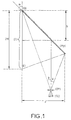
Actuellement, les dispositifs de rétroprojection présentant un écran situé entre l'observateur et le générateur d'image qu'il s'agisse d'un tube à rayon cathodique ou d'un modulateur à cristal liquide fonctionnent selon un schéma commun illustré en figure 1. L'image issue du générateur d'image (GI) via une optique de projection (OP) est renvoyée à l'aide d'un miroir principal Mp vers l'écran, le miroir Mp étant orienté typiquement d'un angle α de 45° par rapport à l'écran et permettant de réduire de moitié l'encombrement entre générateur d'image et écran par rapport à une projection frontale de l'image sur l'écran.Currently, rear projection devices having a screen located between the observer and the image generator, whether it is a cathode ray tube or a liquid crystal modulator, operate according to a common diagram illustrated in FIG. 1 The image from the image generator (GI) via a projection optic (OP) is returned using a main mirror M p towards the screen, the mirror M p being typically oriented by an angle α of 45 ° relative to the screen and making it possible to reduce by half the size between image generator and screen compared to a frontal projection of the image on the screen.
Pour réduire davantage la profondeur e du rétroprojecteur, l'invention propose un dispositif de rétroprojection dans lequel l'angle entre l'écran (E) et le miroir de renvoi Mp peut être abaissé grâce à la présence d'un composant optique de type "mélangeur" situé à proximité du plan sur lequel l'image finale se forme.To further reduce the depth e of the overhead projector, the invention provides a rear projection device in which the angle between the screen (E) and the deflecting mirror M p can be reduced thanks to the presence of an optical component of the type "mixer" located near the plane on which the final image is formed.
Plus précisément, l'invention a pour objet un dispositif de rétroprojection comprenant un système (GI) de génération d'image de petite taille, une optique de projection transformant l'image de petite taille en une image de grande taille (I1) et un écran (E) sur lequel l'image finale (If) est formée caractérisé en ce qu'il comprend au moins un composant de renvoi (MR) et un composant optique de mélange (OM) à proximité de l'écran (E), capable de réfléchir au voisinage d'une incidence moyenne θ1 la quasi-totalité de l'image (I1) en une image (I2) et capable de transmettre au voisinage d'une incidence moyenne θo la quasi-totalité de l'image (If) créée par réflexion de l'image (I2) sur le composant (MR).More specifically, the subject of the invention is a rear projection device comprising a system (GI) for generating a small image, a projection optic transforming the small image into a large image (I 1 ) and a screen (E) on which the final image (I f ) is formed, characterized in that it comprises at least one deflection component (MR) and an optical mixing component (OM) near the screen (E ), capable of reflecting in the vicinity of an average incidence θ 1 almost all of the image (I 1 ) in an image (I 2 ) and capable of transmitting in the vicinity of an average incidence θ o almost all of the image (I f ) created by reflection of the image (I 2 ) on the component (MR).
Ainsi le composant optique de mélange (OM) est caractérisé par le fait qu'il est utilisé localement à la fois en transmission et en réflexion.Thus the optical mixing component (OM) is characterized by the fact that it is used locally both in transmission and in reflection.
Les deux composants optiques (OM) et (MR) respectivement de mélange et de renvoi sont ainsi associés pour réduire l'encombrement du dispositif de rétroprojection.The two optical components (OM) and (MR) respectively of mixing and return are thus associated to reduce the size of the rear projection device.
De préférence, le composant optique de mélange peut être :
- un miroir sélectif en polarisation, capable de réfléchir un premier type de polarisation et capable de transmettre l'autre type de polarisation. Il peut avantageusement s'agir d'un miroir à cristal liquide cholestérique ;
- un composant optique diffractif possédant une structure réseau dont les propriétés de réflexion sont sélectives en fonction de l'angle d'incidence du flux lumineux.
- a selective polarization mirror, capable of reflecting a first type of polarization and capable of transmitting the other type of polarization. It can advantageously be a cholesteric liquid crystal mirror;
- a diffractive optical component having a grating structure whose reflection properties are selective as a function of the angle of incidence of the light flux.
De préférence, le générateur d'image (GI) est un ensemble associant un modulateur à cristal liquide et une source d'éclairage, présentant une étendue géométrique plus faible que celle issue des tubes à rayon cathodique.Preferably, the image generator (GI) is an assembly associating a liquid crystal modulator and a lighting source, having a smaller geometric extent than that coming from cathode ray tubes.
Le rétroprojecteur selon l'invention peut avantageusement comprendre deux composants optiques de renvoi (OM)1 et (OM)r de manière à diminuer encore plus l'encombrement du dispositif en confinant le trajet optique du flux lumineux, c'est-à-dire en lui faisant faire plusieurs "allers" et "retours". Plus précisément, ce dispositif comprend un composant (OM)1 situé à proximité de l'écran (E), un composant (OM)r situé entre le composant (OM)1 et un composant optique de renvoi classique (MR), le composant (OM)r étant capable de transmettre la quasi-totalité de l'image (I1) et la quasi-totalité de l'image (I2) créée par réflexion de l'image (I1) sur le composant (MR) et le composant (OM)r étant capable de réfléchir la quasi-totalité de l'image (I'2) créée par réflexion de la quasi-totalité de l'image (I2) sur le composant optique de mélange (OM)1, l'image (I'2) étant réfléchie en l'image (If) transmise par le composant (OM)1.The overhead projector according to the invention can advantageously comprise two optical return components (OM) 1 and (OM) r so as to further reduce the size of the device by confining the optical path of the light flux, that is to say by making him do several "back and forth". More specifically, this device comprises a component (OM) 1 located near the screen (E), a component (OM) r located between the component (OM) 1 and a conventional optical reference component (MR), the component (OM) r being capable of transmitting almost all of the image (I 1 ) and almost all of the image (I 2 ) created by reflection of the image (I 1 ) on the component (MR) and the component (OM) r being capable of reflecting almost all of the image (I ′ 2 ) created by reflection of almost all of the image (I 2 ) on the optical mixing component (OM) 1 , the image (I ′ 2 ) being reflected in the image (I f ) transmitted by the component (OM) 1 .
L'invention sera mieux comprise et d'autres avantages apparaîtront à la lecture de la description qui va suivre, donnée à titre non limitatif et grâce aux figures annexées parmi lesquelles :
- la figure 1 illustre un schéma de rétroprojection selon l'art antérieur utilisant un miroir situé à 45° de l'écran ;
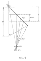
- la figure 2 schématise un dispositif de rétroprojection selon l'art antérieur, dans lequel le générateur d'image (GI) est désaxé par rapport à l'optique de projection (OP) ;
- la figure 3 illustre un exemple de dispositif de rétroprojection selon l'invention utilisant un composant (OM) ;
- la figure 4 schématise un exemple de dispositif de rétroprojection dans lequel le composant (OM) est sélectif en polarisation ;
- la figure 5 illustre la réalisation d'une structure réseau photoinduite par l'interférence de deux ondes optiques sphériques ;
- la figure 6 illustre un exemple de dispositif de rétroprojection selon l'invention utilisant deux composants optiques de mélange (OM)1 et (OM)r.
- FIG. 1 illustrates a rear projection diagram according to the prior art using a mirror located at 45 ° from the screen;
- Figure 2 shows schematically a rear projection device according to the prior art, in which the image generator (GI) is offset with respect to the projection optics (OP);
- FIG. 3 illustrates an example of a rear projection device according to the invention using a component (OM);
- FIG. 4 diagrammatically shows an example of a rear projection device in which the component (OM) is selective in polarization;
- FIG. 5 illustrates the production of a photoinduced network structure by the interference of two spherical optical waves;
- FIG. 6 illustrates an example of a rear projection device according to the invention using two optical mixing components (OM) 1 and (OM) r .
La figure 1 illustre une configuration de rétroprojecteur selon l'invention dans laquelle le générateur d'images (GI) crée via une optique de projection (OP) un faisceau lumineux venant se réfléchir sur le miroir de renvoi (Mp) pour former sur l'écran une image (I). Contenu de l'optique de projection utilisée conditionnant l'angle θ, l'encombrement e de ce dispositif est fourni par l'équation suivante (1) : e = (h+H) sin αcosθ/cs(α-θ)
- si h représente la position du rayon central du faisceau lumineux formant l'image (I), par rapport au point (O) définissant le sommet de l'écran ;
- si 2H représente la hauteur de l'image (I);
- si α représente l'angle entre l'écran (E) et le miroir (Mp).
- if h represents the position of the central ray of the light beam forming the image (I), relative to the point (O) defining the top of the screen;
- if 2H represents the height of the image (I);
- if α represents the angle between the screen (E) and the mirror (Mp).
A titre d'exemple, lorsque l'optique de projection (OP) présente une focale de 50 mm (soit une projection au grandissement d'environ 13,5), le générateur d'images a une diagonale de 7,6 cm (3"), l'écran a une diagonale de 101 cm (500 x 900 mm2) on a pour une position α = 45° avec θ = 20° et 2H = 500 mm, un encombrement e de 367 mm.For example, when the projection optics (OP) has a focal length of 50 mm (i.e. a projection at approximately 13.5 magnification), the image generator has a diagonal of 7.6 cm (3 "), the screen has a diagonal of 101 cm (500 x 900 mm 2 ), for a position α = 45 ° with θ = 20 ° and 2H = 500 mm, a footprint e of 367 mm .
Notons qu'il est possible de réduire cet encombrement e, en envisageant un fonctionnement hors d'axe, c'est-à-dire en décentrant le générateur d'images (GI) par rapport à l'optique de projection( OP). La figure 2 illustre cette configuration dans laquelle on déporte le rayon central d'un angle dθ0A et donc le centre de l'image d'une hauteur dh0A avec tgdθ0A = dh0A.tgθ/H
l'angle maximum θmax égal à θ+dθ0A permet de désaxer le système tout en confinant l'ensemble de l'image (I) sur l'écran.Note that it is possible to reduce this size e, by envisaging an off-axis operation, that is to say by off-centering the image generator (GI) relative to the projection optics (OP). FIG. 2 illustrates this configuration in which the central radius of an angle dθ 0A is offset and therefore the center of the image with a height dh 0A with tgdθ 0A = dh 0A .tgθ / H
the maximum angle θmax equal to θ + dθ 0A makes it possible to offset the system while confining the whole of the image (I) on the screen.
Ainsi pour α = 45°, θ = 20°, 2H = 500 mm, dhOA = H/2, dθ0A = 10°.So for α = 45 °, θ = 20 °, 2H = 500 mm, dh OA = H / 2, dθ 0A = 10 °.
On obtient un encombrement e donné par l'équation (1) d'une valeur de 286 mm.We obtain a space requirement e given by equation (1) with a value of 286 mm.
La figure 3 illustre un dispositif de rétroprojection selon l'invention rendu plus compact que les dispositifs de rétroprojection selon l'art antérieur, grâce à l'association d'au moins un miroir classique de renvoi (MR) et d'un composant optique permettant à la fois le "repli" du faisceau lumineux créé par le générateur d'image (GI) et la transmission dudit faisceau au niveau de l'écran de visualisation (E). La présence d'un tel composant de mélange permet la transmission quasi-totale de l'image, contrairement au miroir semi-réfléchissant que l'on pourrait être tenté d'utiliser pour parvenir au même confinement optique, mais qui présenterait une perte de flux lumineux environ 4 fois plus importante.FIG. 3 illustrates a rear projection device according to the invention made more compact than the rear projection devices according to the prior art, thanks to the association of at least one conventional deflection mirror (MR) and an optical component allowing both the "fallback" of the light beam created by the image generator (GI) and the transmission of said beam at the level of the display screen (E). The presence of such a mixing component allows the almost total transmission of the image, unlike the semi-reflecting mirror which one might be tempted to use to achieve the same optical confinement, but which would present a loss of flux. about 4 times brighter.
Le schéma de la figure 3 illustre le principe général du dispositif de rétroprojection selon l'invention. A partir d'un générateur d'image (GI), de préférence de type modulateur à cristal liquide (LCD) associé à une source d'éclairage, présentant une faible divergence incidente et un faible encombrement, on génère par l'intermédiaire d'une optique de projection (OP) une image virtuelle de grande taille (I1) qui est une première fois réfléchie, au voisinage d'une incidence moyenne θ1 par le composant optique de mélange (OM) pour former une deuxième image virtuelle (I2). Celle-ci est ensuite réfléchie par le composant de renvoi (MR) pour former l'image finale (If) sur l'écran (E), transmise par le composant (OM) au voisinage de l'incidence normale θo.The diagram in FIG. 3 illustrates the general principle of the rear projection device according to the invention. From an image generator (GI), preferably of the liquid crystal modulator (LCD) type associated with a lighting source, having a low incident divergence and a small size, it is generated by means of projection optics (OP) a large virtual image (I 1 ) which is first reflected, in the vicinity of an average incidence θ 1 by the optical mixing component (OM) to form a second virtual image (I 2 ). This is then reflected by the return component (MR) to form the final image (I f ) on the screen (E), transmitted by the component (OM) in the vicinity of the normal incidence θ o .
Notons que l'optique (OP) et le générateur d'image (GI) sont de préférence rapportés dans l'encombrement e grâce à la présence d'un miroir auxiliaire de renvoi classique (non représenté sur la figure 3).It should be noted that the optics (OP) and the image generator (GI) are preferably reported in the dimensions e thanks to the presence of a conventional auxiliary return mirror (not shown in FIG. 3).
Dans le cas présent la hauteur h est définie comme suit :
h = H/tg2α tg(α+θ)
et e = H sin αcosθ/sin 2α.sin (α+θ)In the present case the height h is defined as follows:
h = H / tg2α tg (α + θ)
and e = H sin αcosθ / sin 2α.sin (α + θ)
La hauteur hmin étant définie de manière à ce que toute l'image réfléchie par (OM) arrive sur le miroir de renvoi (MR) pour générer l'image (If).
avec α = 15° θ = 20° 2H = 500 mm
on obtient hmin ∼ 618 mm et un encombrement e de 212 mm.The height h min being defined so that the entire image reflected by (OM) arrives at the reflecting mirror (MR) to generate the image (If).
with α = 15 ° θ = 20 ° 2H = 500 mm
h min ∼ 618 mm is obtained and a footprint e of 212 mm .
Dans un premier exemple de réalisation, le composant optique de mélange (OM) est un miroir cholestérique sélectif en polarisation. Il peut par exemple réfléchir une lumière qui présente une polarisation de type "circulaire gauche" et transmettre sans perte une polarisation de type "circulaire droite".In a first embodiment, the optical mixing component (OM) is a polarizing selective cholesteric mirror. It can for example reflect a light which has a polarization of the "left circular" type and transmit without loss a polarization of the "right circular" type.
A ce titre le dispositif illustré en figure 4 met en évidence les différents changements de polarisation de la lumière :As such, the device illustrated in FIG. 4 highlights the different changes in light polarization:
A partir du générateur d'image (GI) de type (LCD), on crée une lumière polarisée rectilignement, on transforme cette polarisation avec une lame quart d'onde (λ/4) en circulaire gauche. le composant cholestérique (OM) réfléchit cette lumière sans en changer la polarisation contrairement à un réflecteur classique. La lumière réfléchie polarisée "circulaire gauche" est ensuite réfléchie par le réflecteur (MR) type miroir métallique, créant par là même une lumière polarisée de type "circulaire droite" (les flèches indiquées sur le schéma sont relatives au sens dans lequel tourne la polarisation de la lumière au court de son trajet optique).From the image generator (GI) of the type (LCD), a linearly polarized light is created, this polarization is transformed with a quarter wave plate (λ / 4) into a left circular. the cholesteric component (OM) reflects this light without changing the polarization unlike a conventional reflector. The polarized reflected light "circular left" is then reflected by the reflector (MR) type metal mirror, thereby creating polarized light of the type "circular right" (the arrows indicated on the diagram relate to the direction in which the polarization rotates of light during its optical path).
La lumière polarisée "circulaire droite" est transmise par le composant (OM) et parvient ainsi sur l'écran depuis lequel les images sont perçues par un observateur situé du côté opposé au générateur d'image (GI) par rapport à l'écran.Polarized "right circular" light is transmitted by the component (OM) and thus reaches the screen from which the images are perceived by an observer located on the side opposite the image generator (GI) relative to the screen.
Plus précisément, le composant (OM) peut comprendre des films de polymères contenant du cristal liquide cholestérique, la biréfringence élevée de ce type de matériau permet d'atteindre des bandes spectrales (dans lesquelles les conditions de réflexion et de transmission requises sont satisfaites) importantes, supérieures à 80 nm.More specifically, the component (OM) can comprise polymer films containing cholesteric liquid crystal, the high birefringence of this type of material makes it possible to reach significant spectral bands (in which the required conditions of reflection and transmission are satisfied) , greater than 80 nm.
On peut ainsi couvrir l'ensemble du domaine spectral visible soit environ 200 nm utile environ, en superposant 2 ou 3 films de ce type, chacun étant centré sur des longueurs d'onde différentes. De tels composants existent, actuellement dans des dimensions qui sont de l'ordre de 30 x 30 cm2. Le centrage de leur bande spectral peut être obtenu en contrôlant la température de polymérisation du film de polymère (SID Digest 94 ; p 399-402 : "Cholesteric reflectors with a color pattern").It is thus possible to cover the entire visible spectral range, ie approximately 200 nm useful approximately, by superimposing 2 or 3 films of this type, each being centered on different wavelengths. Such components exist, currently in dimensions which are of the order of 30 x 30 cm 2 . The centering of their spectral band can be obtained by controlling the polymerization temperature of the polymer film (SID Digest 94; p 399-402: "Cholesteric reflectors with a color pattern").
En effet, les cristaux liquides cholestériques s'organisent en hélice, le pas de l'hélice pouvant varier avec la température conditionne la longueur d'onde réfléchie. Il suffit ainsi de régler la température pour régler ce pas d'hélice, puis de polymériser le film pour geler l'orientation du cristal liquide dispersé dans le polymère.Indeed, cholesteric liquid crystals are organized in a helix, the pitch of the helix can vary with temperature conditions the reflected wavelength. You just have to set the temperature to set this no helix, then polymerize the film to freeze the orientation of the liquid crystal dispersed in the polymer.
Dans un second exemple, la fonction de mélange du composé (OM) peut être réalisée grâce à la présence d'un réseau de diffraction.In a second example, the compound mixing function (OM) can be achieved thanks to the presence of a diffraction grating.
Le réseau diffractif est conçu pour être opérationnel selon l'angle θ1 défini en figure 3 alors que la polarisation de la lumière peut être quelconque. Dans le cas de générateur d'image (LCD), on est en présence d'une faible étendue de la source de projection, ce qui permet de réfléchir la quasi-totalité de la lumière émise même si la structure réseau possède une acceptance angulaire faible.The diffractive grating is designed to be operational according to the angle θ 1 defined in FIG. 3 while the polarization of the light can be arbitrary. In the case of an image generator (LCD), we are in the presence of a small extent of the projection source, which makes it possible to reflect almost all of the light emitted even if the network structure has a low angular acceptance. .
Lorsque la lumière a été réfléchie par le composant (OM), elle est à nouveau réfléchie par le composant de renvoi (MR) et arrive à nouveau sur le composant (OM) mais sous une incidence θo proche de la normale qui n'est pas dans la bande passante angulaire du composant diffractif de volume (OM).When the light has been reflected by the component (OM), it is again reflected by the return component (MR) and arrives again on the component (OM) but at an incidence θ o close to normal which is not not in the angular bandwidth of the volume diffractive component (OM).
Pour réaliser la structure réseau nécessaire, on peut utiliser des matériaux type gélatine bichromatée ou photopolymère dans lesquels on est en mesure de créer des variations d'indice pouvant être compris entre 0,05 et 0,1.To achieve the necessary network structure, materials such as dichromated gelatin or photopolymer can be used in which it is possible to create index variations which may be between 0.05 and 0.1.
Ces variations d'indice peuvent être photoinduites à partir de 2 ondes sphériques Σ et Σ' comme illustrées en figure 5, dont les centres de courbures 0 et 0' sont tels que :
- (0) est situé au niveau du centre de l'objectif de projection (OP) ;
- (0') est le symétrique de (0) par rapport au composant diffractif de mélange (OM).
- (0) is located at the center of the projection lens (OP);
- (0 ') is the symmetric of (0) with respect to the diffractive mixture component (OM).
les strates ainsi créées sont parallèles au plan du composant et l'on obtient une fonction miroir non dispersive en longueur d'onde : elle fonctionne au voisinage d'une incidence donnée et pour une largeur spectrale qui dépend principalement de la variation d'indice photoinduite dans le matériau.the strata thus created are parallel to the plane of the component and a non-dispersive wavelength mirror function is obtained: it operates in the vicinity of a given incidence and for a spectral width which mainly depends on the variation of photoinduced index in the material.
Pour réfléchir efficacement les trois couleurs primaires rouge, verte et bleue, on peut réaliser une superposition de plusieurs composants comprenant chacun, au moins une fonction miroir, centrée sur des composantes spectrales différentes. On peut également réaliser le multiplexage dans un même film de plusieurs fonctions miroirs, chacune centrées sur les composantes spectrales, Rouge, Vert, Bleu.To effectively reflect the three primary colors red, green and blue, it is possible to create a superposition of several components each comprising, at least one mirror function, centered on different spectral components. We can also carry out the multiplexing in the same film of several mirror functions, each centered on the spectral components, Red, Green, Blue.
Dans une autre variante de l'invention, on utilise un composant optique de mélange supplémentaire (OMr) situé entre le composant (OM)1 et le miroir (MR).In another variant of the invention, an additional optical mixing component (OM r ) is used located between the component (OM) 1 and the mirror (MR).
Une telle configuration est illustrée en figure 6 pour montrer la faisabilité d'un dispositif encore plus compact. Les deux composants de mélange (OM) et (OM)r possèdent des propriétés de réflexion et transmission adaptées aux incidences utilisées. Leur bande passante angulaire peut typiquement être adaptée à l'aide de la valeur de la variation d'indice photoinduite dans le cas de l'utilisation de composants diffractifs. La figure 6 illustre la formation de l'image finale (If) sur l'écran à partir de l'image (I1) créée par le générateur d'images (GI). L'image (I1) est transmise par le composant (OM)r, puis réfléchie en image (I2) par le miroir de renvoi (MR). L'image (I2) est également transmise par le composant (OM)r, et réfléchie en image (I'2) par le composant (OM)1, pour être réfléchie par le composant (OM)r en l'image (If) transmise par le composant (OM)1.Such a configuration is illustrated in FIG. 6 to show the feasibility of an even more compact device. The two mixing components (OM) and (OM) r have reflection and transmission properties adapted to the incidences used. Their angular bandwidth can typically be adapted using the value of the variation of photoinduced index in the case of the use of diffractive components. FIG. 6 illustrates the formation of the final image (I f ) on the screen from the image (I 1 ) created by the image generator (GI). The image (I 1 ) is transmitted by the component (OM) r , then reflected in the image (I 2 ) by the reflecting mirror (MR). The image (I 2 ) is also transmitted by the component (OM) r , and reflected in the image (I ' 2 ) by the component (OM) 1 , to be reflected by the component (OM) r in the image ( I f ) transmitted by the component (OM) 1 .
Par rapport au dispositif illustré en figure 3, le composant (OM)r permet de "remonter l'image" dans l'angle défini par l'écran et le miroir de renvoi (MR). Il devient possible de définir hmin = H et l'encombrement e est dans ce cas exprimé par l'équation suivante :
e = H sin(π/4 - α + 3θ/2) / sin 2θ.sin (π/2 - α + θ/2). On obtient dans ce cas avec α = 15°, θ = 20°, 2H = 500 mm, un encombrement e d'environ 188 mm.Compared to the device illustrated in FIG. 3, the component (OM) r makes it possible to "raise the image" in the angle defined by the screen and the return mirror (MR). It becomes possible to define h min = H and the size e is in this case expressed by the following equation:
e = H sin (π / 4 - α + 3θ / 2) / sin 2θ.sin (π / 2 - α + θ / 2). In this case we obtain with α = 15 °, θ = 20 °, 2H = 500 mm, a footprint e of approximately 188 mm .
Notons que les architectures optiques proposées utilisent préférentiellement des objectifs de projection (OP) fonctionnant sur l'axe, ce qui présente l'avantage de simplifier leur combinaison optique. Néanmoins, compte tenu de la faible étendue géométrique du faisceau d'éclairage des générateurs d'image de type (LCD), on peut aussi envisager un fonctionnement hors d'axe de quelques degrés, sans augmenter notablement la complexité de ces objectifs comme cela est validé en figure 2 dans le cas de dispositifs de rétroprojection selon l'art antérieur.Note that the optical architectures proposed preferentially use projection objectives (OP) operating on the axis, which has the advantage of simplifying their optical combination. However, taking into account the small geometrical extent of the lighting beam of the image generators of the type (LCD), one can also envisage an operation off axis of a few degrees, without appreciably increasing the complexity of these objectives as it is validated in FIG. 2 in the case of rear projection devices according to the prior art.
Claims (8)
Applications Claiming Priority (2)
| Application Number | Priority Date | Filing Date | Title |
|---|---|---|---|
| FR9504177 | 1995-04-07 | ||
| FR9504177A FR2732783B1 (en) | 1995-04-07 | 1995-04-07 | COMPACT BACK PROJECTION DEVICE |
Publications (2)
| Publication Number | Publication Date |
|---|---|
| EP0736795A1 true EP0736795A1 (en) | 1996-10-09 |
| EP0736795B1 EP0736795B1 (en) | 2003-08-13 |
Family
ID=9477883
Family Applications (1)
| Application Number | Title | Priority Date | Filing Date |
|---|---|---|---|
| EP96400712A Expired - Lifetime EP0736795B1 (en) | 1995-04-07 | 1996-04-02 | Compact rear projection device |
Country Status (5)
| Country | Link |
|---|---|
| US (1) | US5734447A (en) |
| EP (1) | EP0736795B1 (en) |
| JP (1) | JP3877236B2 (en) |
| DE (1) | DE69629411T2 (en) |
| FR (1) | FR2732783B1 (en) |
Cited By (4)
| Publication number | Priority date | Publication date | Assignee | Title |
|---|---|---|---|---|
| WO1998019213A1 (en) * | 1996-10-31 | 1998-05-07 | Sanyo Electric Co., Ltd. | Back projection display |
| FR2764462A1 (en) * | 1997-06-10 | 1998-12-11 | Thomson Multimedia Sa | IMPROVEMENT IN PROJECTION SYSTEMS |
| GB2402497A (en) * | 2000-08-16 | 2004-12-08 | Sony Electronics Inc | Optical arrangement for a rear projection television receiver having reduced depth |
| CN110462489A (en) * | 2017-03-27 | 2019-11-15 | 索尼公司 | Image display device and image-displaying member |
Families Citing this family (13)
| Publication number | Priority date | Publication date | Assignee | Title |
|---|---|---|---|---|
| CA2193790C (en) | 1995-12-29 | 2001-03-13 | Duke University | Projecting images |
| FR2755516B1 (en) | 1996-11-05 | 1999-01-22 | Thomson Csf | COMPACT ILLUMINATION DEVICE |
| FR2755530B1 (en) * | 1996-11-05 | 1999-01-22 | Thomson Csf | VISUALIZATION DEVICE AND FLAT TELEVISION SCREEN USING THE SAME |
| US6227669B1 (en) * | 1998-05-26 | 2001-05-08 | Industrial Technology Research Institute | Illumination device and image projection apparatus comprising the device |
| FR2813128B1 (en) | 2000-08-18 | 2003-01-17 | Thomson Csf | LIQUID CRYSTAL DISPLAY DEVICE WITH BIREFRINGENCE COMPENSATOR |
| CN1220026C (en) * | 2000-08-18 | 2005-09-21 | 林德股份公司 | Method for producing air separation installation |
| GB0029340D0 (en) * | 2000-11-30 | 2001-01-17 | Cambridge 3D Display Ltd | Flat panel camera |
| FR2819061B1 (en) * | 2000-12-28 | 2003-04-11 | Thomson Csf | POLARIZATION CONTROL DEVICE IN AN OPTICAL LINK |
| US6857750B2 (en) * | 2002-06-27 | 2005-02-22 | Koninklijke Philips Electronics N.V. | Offset projection for slim rear projection displays |
| JP2006208786A (en) * | 2005-01-28 | 2006-08-10 | Dainippon Printing Co Ltd | Reflection element and projection system provided with the same |
| TWI303347B (en) * | 2006-02-07 | 2008-11-21 | Young Optics Inc | Rear projection display apparatus and images adjusting method thereof |
| CN102984489B (en) * | 2012-12-07 | 2015-09-09 | 广东威创视讯科技股份有限公司 | A kind of back projection TV light path design method |
| US9778475B2 (en) * | 2014-11-06 | 2017-10-03 | The United States of America as represesnted by the Secretary of the Air Forice | Universal polarization converter |
Citations (3)
| Publication number | Priority date | Publication date | Assignee | Title |
|---|---|---|---|---|
| US3711188A (en) * | 1970-06-10 | 1973-01-16 | Visidyne Inc | Compact optical display system |
| EP0488590A1 (en) * | 1990-11-30 | 1992-06-03 | THORN EMI plc | Display device |
| EP0657769A1 (en) * | 1993-12-10 | 1995-06-14 | Koninklijke Philips Electronics N.V. | Image projection system |
Family Cites Families (17)
| Publication number | Priority date | Publication date | Assignee | Title |
|---|---|---|---|---|
| US3941467A (en) * | 1974-10-29 | 1976-03-02 | Kaptron, Inc. | Optical projector/reader |
| JP2569632B2 (en) * | 1987-11-26 | 1997-01-08 | カシオ計算機株式会社 | Rear projection display |
| FR2665773B1 (en) * | 1990-08-10 | 1993-08-20 | Thomson Csf | IMAGE PROJECTION DEVICE USING TWO ORTHOGONAL LIGHT POLARIZATION COMPONENTS. |
| FR2669126B1 (en) * | 1990-11-09 | 1993-01-22 | Thomson Csf | SYSTEM FOR VIEWING IMAGES PROVIDED BY A SPATIAL MODULATOR WITH ENERGY TRANSFER. |
| FR2669127B1 (en) * | 1990-11-09 | 1993-01-22 | Thomson Csf | TWO-BEAM POLARIZED IMAGE PROJECTOR BY MATRIX SCREEN. |
| FR2674391B1 (en) * | 1991-03-19 | 1993-06-04 | Thomson Csf | BROADBAND INTERCORRELATION DEVICE AND DEVICE USING THE SAME. |
| FR2674708B1 (en) * | 1991-03-29 | 1997-01-24 | Thomson Csf | ELECTRIC TRANSVERSE FILTER WITH OPTICAL OPERATION. |
| FR2676302B1 (en) * | 1991-05-07 | 1993-07-16 | Thomson Csf | METHOD FOR READING INFORMATION CONTAINED IN AN OPTICAL DISC. |
| FR2676853B1 (en) * | 1991-05-21 | 1993-12-03 | Thomson Csf | OPTICAL WRITING AND READING METHOD ON HIGH DENSITY STORAGE INFORMATION MEDIUM. |
| FR2680882B1 (en) * | 1991-08-06 | 1993-10-29 | Thomson Csf | ORPTIMIZED LIGHT EFFICIENCY IMAGE PROJECTOR. |
| FR2681988A1 (en) * | 1991-09-27 | 1993-04-02 | Thomson Csf | DEFLECTION POWER LASER. |
| FR2681953B1 (en) * | 1991-10-01 | 1993-11-05 | Thomson Csf | FREQUENCY CORRELATOR. |
| FR2684198B1 (en) * | 1991-11-22 | 1994-09-23 | Thomson Csf | SCREEN FOR IMAGE PROJECTION. |
| FR2685100A1 (en) * | 1991-12-17 | 1993-06-18 | Thomson Csf | OPTICAL POLARIZATION SEPARATOR AND APPLICATION TO A VISUALIZATION SYSTEM. |
| FR2696014B1 (en) * | 1992-09-18 | 1994-11-04 | Thomson Csf | Phase conjugation mirror. |
| FR2699295B1 (en) * | 1992-12-15 | 1995-01-06 | Thomson Csf | Optical processing device for electrical signals. |
| FR2707447B1 (en) * | 1993-07-09 | 1995-09-01 | Thomson Csf | Color display device. |
-
1995
- 1995-04-07 FR FR9504177A patent/FR2732783B1/en not_active Expired - Fee Related
-
1996
- 1996-04-02 EP EP96400712A patent/EP0736795B1/en not_active Expired - Lifetime
- 1996-04-02 DE DE69629411T patent/DE69629411T2/en not_active Expired - Fee Related
- 1996-04-03 US US08/626,961 patent/US5734447A/en not_active Expired - Fee Related
- 1996-04-05 JP JP08426396A patent/JP3877236B2/en not_active Expired - Fee Related
Patent Citations (3)
| Publication number | Priority date | Publication date | Assignee | Title |
|---|---|---|---|---|
| US3711188A (en) * | 1970-06-10 | 1973-01-16 | Visidyne Inc | Compact optical display system |
| EP0488590A1 (en) * | 1990-11-30 | 1992-06-03 | THORN EMI plc | Display device |
| EP0657769A1 (en) * | 1993-12-10 | 1995-06-14 | Koninklijke Philips Electronics N.V. | Image projection system |
Cited By (6)
| Publication number | Priority date | Publication date | Assignee | Title |
|---|---|---|---|---|
| WO1998019213A1 (en) * | 1996-10-31 | 1998-05-07 | Sanyo Electric Co., Ltd. | Back projection display |
| FR2764462A1 (en) * | 1997-06-10 | 1998-12-11 | Thomson Multimedia Sa | IMPROVEMENT IN PROJECTION SYSTEMS |
| EP0884898A1 (en) * | 1997-06-10 | 1998-12-16 | THOMSON multimedia | Improvement to projection systems. |
| US6318862B1 (en) | 1997-06-10 | 2001-11-20 | Thomson Multimedia | Projection system employing multiple beam reflections |
| GB2402497A (en) * | 2000-08-16 | 2004-12-08 | Sony Electronics Inc | Optical arrangement for a rear projection television receiver having reduced depth |
| CN110462489A (en) * | 2017-03-27 | 2019-11-15 | 索尼公司 | Image display device and image-displaying member |
Also Published As
| Publication number | Publication date |
|---|---|
| DE69629411D1 (en) | 2003-09-18 |
| EP0736795B1 (en) | 2003-08-13 |
| DE69629411T2 (en) | 2004-07-08 |
| FR2732783A1 (en) | 1996-10-11 |
| US5734447A (en) | 1998-03-31 |
| JPH08339033A (en) | 1996-12-24 |
| JP3877236B2 (en) | 2007-02-07 |
| FR2732783B1 (en) | 1997-05-16 |
Similar Documents
| Publication | Publication Date | Title |
|---|---|---|
| EP0736795B1 (en) | Compact rear projection device | |
| EP0714504B1 (en) | Liquid crystal projector with holographic filtering device | |
| JP3130315B2 (en) | Lighting equipment | |
| EP0633702B1 (en) | Color display device | |
| US7286272B2 (en) | Image display unit | |
| US6595648B1 (en) | Projection display | |
| EP0714522B1 (en) | Holographic projection screen and method for its production | |
| FR2755530A1 (en) | VISUALIZATION DEVICE AND FLAT TELEVISION SCREEN USING THE SAME | |
| EP0572292B1 (en) | Colour beamsplitter and image projector using the same | |
| EP0485268A1 (en) | Matrix screen image projector with two polarized beams | |
| EP0492640B1 (en) | Projector using a hologram | |
| WO1995034832A1 (en) | Holographic projection screen and method for its production | |
| EP0677230B1 (en) | Colour display device and method for producing same | |
| US5877824A (en) | System for illuminating a liquid-crystal screen | |
| EP0937273B1 (en) | Compact lighting device | |
| JPH11295816A (en) | Projection screen and projection display device | |
| EP0740169B1 (en) | Illumination device | |
| FR2693004A1 (en) | Optical collimator for visor of protective helmet etc. - comprises sequence of linear polariser, spherical mirror, slide and flat mirror, with reflection of mirrors controlled by surface coatings | |
| EP0478425B1 (en) | Device which generates a plurality of lightbeams | |
| FR2858068A1 (en) | Head-up display visor has image source comprising imager, optical projection and diffusing screen | |
| CN215897911U (en) | Projector optical device and projector | |
| JPH11308640A (en) | Method and apparatus for virtual image forming | |
| FR2699688A1 (en) | Optical filtering device and application to a liquid crystal projector. | |
| FR2745917A1 (en) | VISUALIZATION DEVICE FOR HELMET VIEWFINDER | |
| WO1995035486A1 (en) | Optical filtering device and use thereof in a liquid crystal projector |
Legal Events
| Date | Code | Title | Description |
|---|---|---|---|
| PUAI | Public reference made under article 153(3) epc to a published international application that has entered the european phase |
Free format text: ORIGINAL CODE: 0009012 |
|
| AK | Designated contracting states |
Kind code of ref document: A1 Designated state(s): DE GB IT NL |
|
| 17P | Request for examination filed |
Effective date: 19970210 |
|
| RAP1 | Party data changed (applicant data changed or rights of an application transferred) |
Owner name: THALES |
|
| 17Q | First examination report despatched |
Effective date: 20011029 |
|
| GRAH | Despatch of communication of intention to grant a patent |
Free format text: ORIGINAL CODE: EPIDOS IGRA |
|
| RIN1 | Information on inventor provided before grant (corrected) |
Inventor name: JOUBERT, CECILE Inventor name: SPITZ, ERICH Inventor name: HUIGNARD, JEAN-PIERRE Inventor name: LOISEAUX, BRIGITTE |
|
| GRAH | Despatch of communication of intention to grant a patent |
Free format text: ORIGINAL CODE: EPIDOS IGRA |
|
| GRAA | (expected) grant |
Free format text: ORIGINAL CODE: 0009210 |
|
| AK | Designated contracting states |
Designated state(s): DE GB IT NL |
|
| REG | Reference to a national code |
Ref country code: GB Ref legal event code: FG4D Free format text: NOT ENGLISH |
|
| REF | Corresponds to: |
Ref document number: 69629411 Country of ref document: DE Date of ref document: 20030918 Kind code of ref document: P |
|
| GBT | Gb: translation of ep patent filed (gb section 77(6)(a)/1977) |
Effective date: 20031113 |
|
| PLBE | No opposition filed within time limit |
Free format text: ORIGINAL CODE: 0009261 |
|
| STAA | Information on the status of an ep patent application or granted ep patent |
Free format text: STATUS: NO OPPOSITION FILED WITHIN TIME LIMIT |
|
| 26N | No opposition filed |
Effective date: 20040514 |
|
| PGFP | Annual fee paid to national office [announced via postgrant information from national office to epo] |
Ref country code: NL Payment date: 20090405 Year of fee payment: 14 Ref country code: IT Payment date: 20090421 Year of fee payment: 14 Ref country code: DE Payment date: 20090327 Year of fee payment: 14 |
|
| PGFP | Annual fee paid to national office [announced via postgrant information from national office to epo] |
Ref country code: GB Payment date: 20090401 Year of fee payment: 14 |
|
| REG | Reference to a national code |
Ref country code: NL Ref legal event code: V1 Effective date: 20101101 |
|
| GBPC | Gb: european patent ceased through non-payment of renewal fee |
Effective date: 20100402 |
|
| PG25 | Lapsed in a contracting state [announced via postgrant information from national office to epo] |
Ref country code: NL Free format text: LAPSE BECAUSE OF NON-PAYMENT OF DUE FEES Effective date: 20101101 |
|
| PG25 | Lapsed in a contracting state [announced via postgrant information from national office to epo] |
Ref country code: DE Free format text: LAPSE BECAUSE OF NON-PAYMENT OF DUE FEES Effective date: 20101103 |
|
| PG25 | Lapsed in a contracting state [announced via postgrant information from national office to epo] |
Ref country code: GB Free format text: LAPSE BECAUSE OF NON-PAYMENT OF DUE FEES Effective date: 20100402 Ref country code: IT Free format text: LAPSE BECAUSE OF NON-PAYMENT OF DUE FEES Effective date: 20100402 |