EP0478425B1 - Device which generates a plurality of lightbeams - Google Patents
Device which generates a plurality of lightbeams Download PDFInfo
- Publication number
- EP0478425B1 EP0478425B1 EP91402506A EP91402506A EP0478425B1 EP 0478425 B1 EP0478425 B1 EP 0478425B1 EP 91402506 A EP91402506 A EP 91402506A EP 91402506 A EP91402506 A EP 91402506A EP 0478425 B1 EP0478425 B1 EP 0478425B1
- Authority
- EP
- European Patent Office
- Prior art keywords
- generating device
- selective mirrors
- light
- selective
- window
- Prior art date
- Legal status (The legal status is an assumption and is not a legal conclusion. Google has not performed a legal analysis and makes no representation as to the accuracy of the status listed.)
- Expired - Lifetime
Links
Images

Classifications
-
- G—PHYSICS
- G02—OPTICS
- G02B—OPTICAL ELEMENTS, SYSTEMS OR APPARATUS
- G02B27/00—Optical systems or apparatus not provided for by any of the groups G02B1/00 - G02B26/00, G02B30/00
- G02B27/10—Beam splitting or combining systems
- G02B27/14—Beam splitting or combining systems operating by reflection only
- G02B27/143—Beam splitting or combining systems operating by reflection only using macroscopically faceted or segmented reflective surfaces
-
- G—PHYSICS
- G02—OPTICS
- G02B—OPTICAL ELEMENTS, SYSTEMS OR APPARATUS
- G02B27/00—Optical systems or apparatus not provided for by any of the groups G02B1/00 - G02B26/00, G02B30/00
- G02B27/10—Beam splitting or combining systems
- G02B27/1006—Beam splitting or combining systems for splitting or combining different wavelengths
Definitions
- the invention relates to a device producing simultaneously several beams of light corresponding to different spectral domains.
- the invention applies particularly (but not exclusively) to the lighting of spatial light modulation screens in color image projectors.
- the image to be projected is formed on the surface of the spatial light modulator screen, the latter generally consisting of a liquid crystal matrix cell.
- the light provided by a light source is spatially modulated by the matrix, and the projected image results from this modulation.
- the low light output of image projectors is linked to various causes, one of which is the loss of light due to the differences between the shape of the screen. spatial modulator to be illuminated and the shape of the section of the light beam coming from the light source.
- the image is provided with a 16/9 format (ratio of length to width).
- An image projector system meeting this definition uses a spatial modulator screen having this 16/9 format.
- the fraction of light energy used to illuminate the rectangle that constitutes the spatial modulator screen corresponds only to the SR / SF ratio of the SR surface of this rectangle to the SF surface of the beam section, that is 0.54 in the best case, that is to say when SR is as large as possible, in format 16 / 9, while being contained in SF.
- the present invention provides a new arrangement of the light source and means which separate the white light beam or primary beam, into several secondary beams each having a different spectral range and a rectangular section.
- the invention is advantageously applied when at least two secondary beams are necessary, particularly with a 16/9 format, whatever the shape of the section of the primary beam, and its use in particular in color video projectors makes it possible to very interestingly improve the light efficiency of the latter.
- a device for generating light beams comprising a light source producing a light beam called the primary beam, the spectrum of which substantially covers that of visible light, a light separator, of the type comprising at least two selective mirrors in wavelength, illuminated by the primary beam and producing in return at least two secondary beams corresponding to different wavelengths, the first and the second of the secondary beams being obtained using respectively of a first and of a second of said wavelength selective mirrors, is characterized in that the first and second selective mirrors are arranged so as to intercept different parts of the section of the primary beam, and in that the light separator further comprises a rear face constituting at least partially a total mirror, the rear face being on the one hand located opposite the light source with respect to the first and second selective mirrors, and being on the other hand in a plane perpendicular to an axis of propagation of the primary beam.
- Figure 1 shows by way of nonlimiting example a device 1 for generating light beams according to the invention.
- the generator device 1 comprises a light source 2 producing a light beam called the primary beam FP.
- the primary beam FP is intended to generate several secondary beams and its spectrum must cover the spectral domains of these secondary beams.
- the spectrum of the primary beam FP corresponds substantially to that of visible light, so as to allow the production of three secondary beams F1, F2, F3 monochrome, the one for blue, another for red and the third for green.
- the primary beam FP is a beam with substantially parallel rays, as obtained with light sources of white light currently commercially available, of the type comprising a parabolic reflector by example.
- a conventional source S of white light placed between a spherical reflector 4 and a collimating lens LC and on the optical axis 5 of the latter, at the center of curvature of the spherical reflector and focal point of the LC lens.
- the source S produces a light 3 collimated by the lens LC so as to form the primary beam FP; the optical axis of the collimating lens constituting the axis of propagation 5 of the primary beam FP.
- the primary beam FP propagates in the direction of a light separating device SL of the type comprising several wavelength selective mirrors, each selective mirror being reflective for a given wavelength.
- a light separating device SL of the type comprising several wavelength selective mirrors, each selective mirror being reflective for a given wavelength.
- Such selective mirrors exist in dichroic cubes (commonly available commercially), which in particular allow on the one hand to reflect two beams of different colors (blue and red for example) in opposite directions, and on the other hand to transmit a third beam of a third color, green for example.
- the light separator SL comprises first and second wavelength selective mirrors M1, M2, interposed on the path of the primary beam FP so that each selective mirror intercepts a part SF1, SF2 different from the FP primary beam section.
- the first mirror M1 for example reflects the wavelengths which correspond to the blue with which it produces a first secondary beam F1; and the second selective mirror M2 reflects for example the wavelengths which correspond to red, with which it produces a second secondary beam F2.
- the light separator SL further comprises a rear face 15 at least partially reflecting all the wavelengths, arranged opposite the light source 2 with respect to the first and second selective mirrors M1, M2.
- the rear face 15 comprises a window 6 intended to transmit a third secondary beam F3.
- the first and second selective mirrors M1, M2 as well as the rear face 15 are carried by a block 16 transparent to light (in glass for example), forming a prism with triangular section seen in the figure 1 according to its section; the rear face 15 being on the hypotenuse face of the prism, the 2 selective mirrors M1, M2 being on the two other faces.
- a first and a second transparent part 7, 8 are applied respectively to the first and the second selective mirrors M1, M2 in order to avoid large angles of refraction at the level of the selective mirrors M1, M2.
- the shape of these parts 7, 8 is such that their entry face respectively 12, 13 and their exit face 16, 17 are normal to the incident and emerging rays respectively.
- the first and second selective mirrors M1, M2, seen from the light source 2 each have an apparent surface SA rectangular.
- the two selective mirrors M1, M2 are inclined on the axis of propagation 5, with which they preferably (but not necessarily) form angles of inclination a1, a2 equal; the apparent surface SA being equal to the real surface SR multiplied by the sine of the angle of inclination a1, a2.
- first and second selective mirrors respectively reflect a first and a second secondary beam F1, F2 corresponding to blue and red, and the section of each of these two secondary beams is equal to the apparent surface of the selective mirror having generated it. .
- the invention finds one of its most interesting applications when each secondary beam F1, F2 is given a rectangular section in 16/9 format; this is because such formats placed one beside the other constitute an almost square surface.
- the first and second selective mirrors M1, M2 are arranged side by side, their length is in a plane perpendicular to that of the figure and their width 11, 12 is greater than their apparent width 11 ′, 12 ′ views from the light assembly 2. If their width 11, 12 is such that, as a function of the angles of inclination a1, a2, their apparent width 11 ′, 12 ′ gives them an apparent surface in 16/9 format, the surface total of the intercepted section of the primary beam FP by the two selective mirrors M1, M2 is close to a square.
- the ratio of the quantity of energy withdrawn to the quantity of energy available in the primary beam FP is improved.
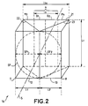
- Figure 2 is a perspective view of the block or prism 16, which illustrates the registration of selective mirrors in the section of the primary beam FP.
- the first and second selective mirrors M1, M2 and the rear face 15 are not materialized in FIG. 2, but they are represented respectively by a first and a second face 22, 23 and a hypothenous face 21 of the prism 16 which carries them: the first selective mirror M1 being on the face 22; the second mirror M2 being on the face 23, and the rear face 15 being on the hypotenuse face 21.
- These mirrors or faces all have the same length L1 given by a height of the prism 16.
- the first and second transparent parts 7, 8 are applied respectively against the faces 22 and 23 of the prism 16 and have the same length L1 as the latter; the input faces 12, 13 of these parts are normal to the axis of propagation 5 of the primary beam FP.
- the primary beam FP has a circular cross section which is shown in FIG. 2 by a circle SF in dotted lines. It is observed that the two entry faces 12, 13 (each in 16/9 format) arranged side by side add their width 11 ′, 12 ′ to form an almost square surface inscribed in the section of the primary beam FP.
- the first and second entry faces 12, 13 have the same surface and the same format as the selective mirrors M1, M2 and these entry faces 12, 13 intercept respectively the first and the second part SF1, SF2 of the section of the primary beam FP.
- the rear face 15 comprises the window 6 already mentioned as well as a third and a fourth mirror M3, M4 arranged on either side of this window 6.
- the window 6 has a length L1 equal and parallel to the length of the faces 12, 13 of the parts 7, 8, that is to say equal to the length of the first and second selective mirrors M1, M2; and its width 13 is equal to the apparent widths 11 ′, 12 ′ of the latter while the rear face 15 has a width 13a twice that of the window 6.
- the window 6 is centered on the propagation axis 5, so that it can be considered to be constituted by a first and a second strip B1, B2, located on either side of the propagation axis 5 and forming respectively a first and a second window half each having the length L1: the first half B1 intercepts with the third mirror M3, the first part SF1 of the section of the primary beam FP; and the second half B2 intercepts with the fourth mirror M4 the second part SF2 of this primary beam section.
- the rear face 15 is perpendicular to the axis of propagation 5, so as to reflect towards the light source 2, the components of the primary beam FP not used to form the secondary beams F1, F2, F3.
- angles of inclination a1, a2 of the first and second mirrors M1, M2 are 45 °, so that the first and the second secondary beams F1, F2 propagate with opposite directions, on a second axis 10 which forms an angle of 90 ° with the axis of propagation 5 of the primary beam FP.
- the first and the second selective mirrors M1, M2 are arranged symmetrically with respect to the axis of propagation 5 and their length is centered with respect to the latter.
- These two selective mirrors are joined by their length; their length being perpendicular to the plane of the figure, their junction 11 is also perpendicular to the plane of the figure, and in the nonlimiting example described, this junction 11 is oriented towards the light source 2 and it is located in the same plane as the axis of propagation 5.
- Window 6 is transparent only for the spectral domain desired for the third secondary beam F3, namely in the example for the wavelength corresponding to green, and it reflects the other components.
- the window 6 being centered on the axis of propagation 5 of the primary beam FP, this axis also constitutes the axis of the third secondary beam F3.
- the operation is as follows: the first selective mirror M1 is interested in the first part SF1 of the primary beam: on the one hand, it reflects the component relating to blue, to constitute the first secondary beam F1 and, on the other hand, it is transparent to the other wavelengths of this part of the primary beam, and it therefore lets red and green pass in the direction of the rear face 15. Vis-à- screw of this first part SF1 of the primary beam which has passed through the first selective mirror M1 (acting for blue), the rear face 15 has the third mirror M3 and a first half or band B1 of the window 6 only transparent to green; the third mirror M3 is a total mirror, that is to say that it reflects all the wavelengths.
- the third mirror M3 reflects towards the source 2 all the components; but the blue component having previously been deflected by the first selective mirror M1, only green and red components are reflected along the propagation axis 5 towards the source 2, by the third mirror M3, components which are symbolized in the figure 1 respectively by an arrow marked r1 and an arrow marked v1.
- the first selective mirror M1 With regard to the light which propagates towards the first half B1 of the window, following the action of the first selective mirror M1, it no longer comprises the components relating to blue; the green being transmitted by this first window half B1, only a red component (symbolized by an arrow marked rf) is reflected in the direction of the light source 2, parallel to the axis of propagation 5.
- the second selective mirror M2 acts for the red.
- the second selective mirror M2 is placed on the path of the second part SF2 of the section of the primary beam FP, and on the one hand it reflects the component relating to the red in order to constitute the second secondary beam F2.
- the second selective mirror M2 is transparent for the other wavelengths; it therefore lets through the green and blue components contained in this second part SF2 of the primary beam section.
- This second part SF2 is itself divided into two fractions, one of which propagates towards the fourth mirror M4, and the other of which propagates towards the second half B2 of window 6.
- the fourth mirror M4 reflects all the wavelengths towards the light source 2, parallel to the axis 5: it therefore reflects towards the source 2 the green and the blue which are the only components transmitted by the second mirror selective M2; which components are shown in FIG. 1 respectively by an arrow v2 and an arrow b2.
- the second half B2 of window is transparent only for green, in order to contribute to obtaining the third secondary beam F3; it therefore reflects towards the light source 2 all the other components, namely in this example blue as illustrated in FIG. 1 by an arrow marked b2 ′.
- This arrangement of the first and second selective mirrors M1, M2 and of the rear face 15 makes it possible to obtain the three secondary beams F1, F2, F3 of different wavelengths and with rectangular sections, in particular in 16/9 format, from of the primary beam section FP. It also makes it possible to return to the light source 2, parallel to the axis of propagation 5, the light which has not been used to constitute the secondary beams F1, F2, F3. Thanks to the reflector 4, this light energy is added to that which has just been produced to constitute the primary beam FP, and it is distributed throughout the entire section of the latter. This recycled light thus tends to increase the share of useful light to constitute the secondary beams F1, F2, F3.
- the first and second selective mirrors M1, M2 and the rear face 15 are formed from elements in themselves conventional.
- the selective mirrors M1, M2 can be produced for example by a stack of thin dielectric layers according to the conventional technique of interference filters.
- These selective mirrors M1, M2 can be produced directly on the faces of the prism 16, but they can also be produced on glass plates and then placed between the prism 16 and the transparent parts 7, 8.
- the window 6 being made up of two parts or bands B1, B2 both transparent to green, but the first of which reflects blue and the second reflects red, these bands can be formed by selective mirrors. The important thing is that they reflect any incident light other than green and they can be replaced by a green band pass filter.
- each secondary beam can be swapped, it suffices to make each selective mirror so that it reflects the desired wavelength range.
- the foregoing description of the rear face 15 applies to the production of three secondary beams F1, F2, F3, of rectangular sections. But the invention retains its interest even when only two secondary beams are necessary: in this case, it suffices to replace the window 6 (transparent to the wavelengths of the third secondary beam F3) by a total mirror reflecting all the lengths of wave, in the same way as the third and fourth mirrors M3, M4.
Description
L'invention se rapporte à un dispositif produisant simultanément plusieurs faisceaux de lumière correspondant à des domaines spectraux différents.The invention relates to a device producing simultaneously several beams of light corresponding to different spectral domains.
On connaît de dispositifs générateurs de faisceaux de lumière correspondant à des longueurs d'onde différente du type comportant des miroirs dichroïques, voir par exemple le document EP-A-0 307 203.There are known light beam generating devices corresponding to different wavelengths of the type comprising dichroic mirrors, see for example the document EP-A-0 307 203.
L'invention s'applique particulièrement (mais non exclusivement) à l'éclairage d'écrans de modulation spatiale de la lumière dans les projecteurs d'images couleur.The invention applies particularly (but not exclusively) to the lighting of spatial light modulation screens in color image projectors.
Dans les projecteurs vidéo d'images, couleur ou non, l'image à projeter est formée sur la surface de l'écran modulateur spatial de lumière, ce dernier étant constitué généralement par une cellule matricielle à cristal liquide. La lumière fournie par une source de lumière est modulée spatialement par la matrice, et l'image projetée résulte de cette modulation.In video image projectors, color or not, the image to be projected is formed on the surface of the spatial light modulator screen, the latter generally consisting of a liquid crystal matrix cell. The light provided by a light source is spatially modulated by the matrix, and the projected image results from this modulation.
L'un des problèmes de ces projeteurs est que leur rendement lumineux est faible, de l'ordre de quelques pour-cent, et ce problème est encore plus sensible avec les projeteurs couleurs. En effet, dans un grand nombre de projecteurs couleurs, l'image polychrome est obtenue par la superposition de trois images monochromes. Dans ce type de projecteur couleur, il est courant d'utiliser une unique source produisant un faisceau de lumière blanche ou faisceau primaire et de séparer ce faisceau primaire en trois faisceaux monochromes correspondant chacun à l'une des couleurs primaires. Chaque faisceau monochrome est modulé par un modulateur spatial, et les trois faisceaux monochromes modulés correspondant chacun à l'une des couleurs primaires sont ensuite superposés pour former l'image.One of the problems with these projectors is that their light output is low, on the order of a few percent, and this problem is even more acute with color projectors. Indeed, in a large number of color projectors, the polychrome image is obtained by the superposition of three monochrome images. In this type of color projector, it is common to use a single source producing a beam of white light or primary beam and to separate this primary beam into three monochrome beams each corresponding to one of the primary colors. Each monochrome beam is modulated by a spatial modulator, and the three modulated monochrome beams each corresponding to one of the primary colors are then superimposed to form the image.
Le faible rendement lumineux des projecteurs d'images est lié à différentes causes, dont l'une réside dans les pertes de lumière dues aux différences entre la forme de l'écran modulateur spatial à éclairer et la forme de la section du faisceau de lumière provenant de la source lumineuse.The low light output of image projectors is linked to various causes, one of which is the loss of light due to the differences between the shape of the screen. spatial modulator to be illuminated and the shape of the section of the light beam coming from the light source.
Ainsi par exemple, dans le cadre du développement des téléviseurs à haute définition et à grand écran, l'image est prévue avec un format 16/9 (rapport de la longueur à la largeur). Un système projecteur d'image répondant à cette définition utilise un écran modulateur spatial ayant ce format 16/9. Dans ce cas, en supposant, suivant le cas le plus courant, que le faisceau de lumière venant de la source ait une section circulaire, la fraction d'énergie lumineuse utilisée pour éclairer le rectangle que constitue l'écran modulateur spatial, correspond seulement au rapport SR/SF de la surface SR de ce rectangle à la surface SF de la section du faisceau, soit 0,54 dans le meilleur des cas, c'est-à-dire lorsque SR est aussi grande que possible, au format 16/9, tout en étant contenu dans SF.For example, in the context of the development of high definition and large screen televisions, the image is provided with a 16/9 format (ratio of length to width). An image projector system meeting this definition uses a spatial modulator screen having this 16/9 format. In this case, assuming, according to the most common case, that the light beam coming from the source has a circular section, the fraction of light energy used to illuminate the rectangle that constitutes the spatial modulator screen, corresponds only to the SR / SF ratio of the SR surface of this rectangle to the SF surface of the beam section, that is 0.54 in the best case, that is to say when SR is as large as possible, in
La présente invention propose un agencement nouveau de la source de lumière et des moyens qui séparent le faisceau de lumière blanche ou faisceau primaire, en plusieurs faisceaux secondaires ayant chacun un domaine spectral différent et une section rectangulaire. L'invention s'applique de manière avantageuse quand au moins deux faisceaux secondaires sont nécessaires, particulièrement avec un format 16/9, quelle que soit la forme de la section du faisceau primaire, et son utilisation notamment dans les projecteurs vidéo couleurs permet d'améliorer de manière très intéressante l'efficacité lumineuse de ces derniers.The present invention provides a new arrangement of the light source and means which separate the white light beam or primary beam, into several secondary beams each having a different spectral range and a rectangular section. The invention is advantageously applied when at least two secondary beams are necessary, particularly with a 16/9 format, whatever the shape of the section of the primary beam, and its use in particular in color video projectors makes it possible to very interestingly improve the light efficiency of the latter.
Selon l'invention, un dispositif générateur de faisceaux de lumière, comprenant une source lumineuse produisant un faisceau de lumière dit faisceau primaire dont le spectre couvre sensiblement celui de la lumière visible, un séparateur de lumière, du type comportant au moins deux miroirs sélectifs en longueur d'onde, éclairé par le faisceau primaire et produisant en retour au moins deux faisceaux secondaires correspondant à des longueurs d'onde différentes, le premier et le second des faisceaux secondaires étant obtenus à l'aide respectivement d'un premier et d'un second desdits miroirs sélectifs en longueur d'onde, est caractérisé en ce que les premier et second miroirs sélectifs sont disposés de façon à intercepter des parties différentes de la section du faisceau primaire, et en ce que le séparateur de lumière comporte en outre une face arrière constituant au moins partiellement un miroir total, la face arrière étant d'une part située à l'opposé de la source lumineuse par rapport aux premier et second miroirs sélectifs, et étant d'autre part dans un plan perpendiculaire à un axe de propagation du faisceau primaire.According to the invention, a device for generating light beams, comprising a light source producing a light beam called the primary beam, the spectrum of which substantially covers that of visible light, a light separator, of the type comprising at least two selective mirrors in wavelength, illuminated by the primary beam and producing in return at least two secondary beams corresponding to different wavelengths, the first and the second of the secondary beams being obtained using respectively of a first and of a second of said wavelength selective mirrors, is characterized in that the first and second selective mirrors are arranged so as to intercept different parts of the section of the primary beam, and in that the light separator further comprises a rear face constituting at least partially a total mirror, the rear face being on the one hand located opposite the light source with respect to the first and second selective mirrors, and being on the other hand in a plane perpendicular to an axis of propagation of the primary beam.
L'invention sera mieux comprise à la lecture de la description qui suit, faite à titre d'exemple non limitatif, en référence aux dessins annexés, parmi lesquels :
- la figure 1 montre schématiquement le dispositif générateur de faisceaux de l'invention,
- la figure 2 montre par une vue en perspective un prisme représenté à la figure 1.
- FIG. 1 schematically shows the beam generator device of the invention,
- FIG. 2 shows a perspective view of a prism shown in FIG. 1.
La figure 1 montre à titre d'exemple non limitatif un dispositif générateur 1 de faisceaux de lumière conforme à l'invention.Figure 1 shows by way of nonlimiting example a device 1 for generating light beams according to the invention.
Le dispositif générateur 1 comprend une source lumineuse 2 produisant un faisceau de lumière appelé faisceau primaire FP. Le faisceau primaire FP est destiné à engendrer plusieurs faisceaux secondaires et son spectre doit couvrir les domaines spectraux de ces faisceaux secondaires. Dans le cas par exemple d'une application à un projecteur d'images couleur le spectre du faisceau primaire FP correspond sensiblement à celui de la lumière visible, de manière à permettre la production de trois faisceaux secondaires F1, F2, F3 monochromes, l'un pour le bleu, un autre pour le rouge et le troisième pour le vert.The generator device 1 comprises a
Le faisceau primaire FP est un faisceau à rayons sensiblement parallèles, tel qu'obtenu avec des sources lumineuses de lumière blanche couramment disponibles dans le commerce, du type comportant un réflecteur parabolique par exemple. On peut aussi utiliser à cet effet, comme montré à la figure 1, une source S classique de lumière blanche placée entre un réflecteur sphérique 4 et une lentille de collimation LC et sur l'axe optique 5 de cette dernière, au centre de courbure du réflecteur sphérique et au foyer de la lentille LC. La source S produit une lumière 3 collimatée par la lentille LC de façon à former le faisceau primaire FP ; l'axe optique de la lentille collimatrice constituant l'axe de propagation 5 du faisceau primaire FP.The primary beam FP is a beam with substantially parallel rays, as obtained with light sources of white light currently commercially available, of the type comprising a parabolic reflector by example. One can also use for this purpose, as shown in FIG. 1, a conventional source S of white light placed between a spherical reflector 4 and a collimating lens LC and on the
Le faisceau primaire FP se propage en direction d'un dispositif séparateur de lumière SL du type comportant plusieurs miroirs sélectifs en longueur d'onde, chaque miroir sélectif étant réfléchissant pour une longueur d'onde donnée. De tels miroirs sélectifs existent dans les cubes dichroïques (couramment disponibles dans le commerce), qui permettent notamment d'une part de réfléchir deux faisceaux de couleurs différentes (bleue et rouge par exemple) dans des directions opposées, et d'autre part de transmettre un troisième faisceau d'une troisième couleur, verte par exemple.The primary beam FP propagates in the direction of a light separating device SL of the type comprising several wavelength selective mirrors, each selective mirror being reflective for a given wavelength. Such selective mirrors exist in dichroic cubes (commonly available commercially), which in particular allow on the one hand to reflect two beams of different colors (blue and red for example) in opposite directions, and on the other hand to transmit a third beam of a third color, green for example.
Suivant une caractéristique de l'invention, le séparateur de lumière SL comporte un premier et un second miroirs sélectifs en longueur d'onde M1, M2, interposés sur le trajet du faisceau primaire FP de façon que chaque miroir sélectif intercepte une partie SF1, SF2 différente de la section du faisceau primaire FP. Le premier miroir M1 réfléchit par exemple les longueurs d'onde qui correspondent au bleu avec lesquelles il réalise un premier faisceau secondaire F1 ; et le second miroir sélectif M2 réfléchit par exemple les longueurs d'onde qui correspondent au rouge, avec lesquelles il réalise un second faisceau secondaire F2.According to a characteristic of the invention, the light separator SL comprises first and second wavelength selective mirrors M1, M2, interposed on the path of the primary beam FP so that each selective mirror intercepts a part SF1, SF2 different from the FP primary beam section. The first mirror M1 for example reflects the wavelengths which correspond to the blue with which it produces a first secondary beam F1; and the second selective mirror M2 reflects for example the wavelengths which correspond to red, with which it produces a second secondary beam F2.
Le séparateur de lumière SL comporte en outre une face arrière 15 au moins partiellement réfléchissante de toutes les longueurs d'onde, disposée à l'opposé de la source lumineuse 2 par rapport au premier et au second miroirs sélectifs M1, M2. Dans l'exemple non limitatif décrit, la face arrière 15 comporte une fenêtre 6 destinée à transmettre un troisième faisceau secondaire F3.The light separator SL further comprises a
Dans un mode de réalisation préféré, le premier et le second miroirs sélectifs M1, M2 ainsi que la face arrière 15 sont portés par un bloc 16 transparent à la lumière (en verre par exemple), formant un prisme à section triangulaire vu sur la figure 1 selon sa section ; la face arrière 15 étant sur la face hypoténuse du prisme, les 2 miroirs sélectifs M1, M2 étant sur les deux autres faces.In a preferred embodiment, the first and second selective mirrors M1, M2 as well as the
Une première et une seconde pièce transparente 7, 8 sont appliquées respectivement sur le premier et le second miroirs sélectifs M1, M2 afin d'éviter des angles de réfraction importants au niveau des miroirs sélectifs M1, M2. La forme de ces pièces 7, 8 est telle que leur face d'entrée respectivement 12, 13 et leur face de sortie 16, 17 soient normales respectivement aux rayons incidents et émergents.A first and a second
Suivant une autre caractéristique de l'invention, les premier et second miroirs sélectifs M1, M2, vus depuis la source lumineuse 2, ont chacun une surface apparente SA rectangulaire.According to another characteristic of the invention, the first and second selective mirrors M1, M2, seen from the
Les deux miroirs sélectifs M1, M2 sont inclinés sur l'axe de propagation 5, avec lequel ils forment de préférence (mais pas impérativement) des angles d'inclinaisons a1, a2 égaux ; la surface apparente SA étant égale à la surface réelle SR multipliée par le sinus de l'angle d'inclinaison a1, a2.The two selective mirrors M1, M2 are inclined on the axis of
Ainsi le premier et le second miroirs sélectifs réfléchissent respectivement un premier et un second faisceaux secondaires F1, F2 correspondant au bleu et au rouge, et la section de chacun de ces deux faisceaux secondaires est égale à la surface apparente du miroir sélectif l'ayant engendré.Thus the first and second selective mirrors respectively reflect a first and a second secondary beam F1, F2 corresponding to blue and red, and the section of each of these two secondary beams is equal to the apparent surface of the selective mirror having generated it. .
En fait l'invention trouve l'une de ses applications les plus intéressantes quand on confère à chaque faisceau secondaire F1, F2 une section rectangulaire au format 16/9 ; ceci du fait que de tels formats placés l'un à côté de l'autre constituent une surface presque carrée.In fact, the invention finds one of its most interesting applications when each secondary beam F1, F2 is given a rectangular section in 16/9 format; this is because such formats placed one beside the other constitute an almost square surface.
En effet, le premier et le second miroirs sélectifs M1, M2 sont disposés côte à côte, leur longueur est dans un plan perpendiculaire à celui de la figure et leur largeur 11, 12 est plus grande que leur largeur apparente 11′, 12′ vues depuis l'ensemble lumineux 2. Si leur largeur 11, 12 est telle, qu'en fonction des angles d'inclinaison a1, a2, leur largeur apparente 11′, 12′ leur confère une surface apparente au format 16/9, la surface totale de la section interceptée du faisceau primaire FP par les deux miroirs sélectifs M1, M2 est proche d'un carré.Indeed, the first and second selective mirrors M1, M2 are arranged side by side, their length is in a plane perpendicular to that of the figure and their
En conséquence, avec le montage de l'invention, on améliore le rapport de la quantité d'énergie prélevée à la quantité d'énergie disponible dans le faisceau primaire FP. Quand on confère aux surfaces apparentes des miroirs sélectifs M1, M2 un format 16/9, on confère aussi un format 16/9 à la section de chacun des premier et second faisceaux secondaires F1, F2, et le rapport de l'énergie lumineuse prélevée à l'énergie disponible dans un faisceau primaire passe à 0, 63, du fait que l'on inscrit alors simultanément, et côte à côte deux rectangles au format 16/9 chacun dans la section circulaire du faisceau primaire ; alors que pour un seul rectangle inscrit, comme dans l'art antérieur, ce rapport est de 0,54 ainsi qu'il a été indiqué dans le préambule.Consequently, with the arrangement of the invention, the ratio of the quantity of energy withdrawn to the quantity of energy available in the primary beam FP is improved. When we give the apparent surfaces of the selective mirrors M1, M2 a 16/9 format, we also give a 16/9 format to the section of each of the first and second secondary beams F1, F2, and the ratio of the light energy taken the energy available in a primary beam goes to 0.63, because one then simultaneously inscribes, side by side, two rectangles in 16/9 format each in the circular section of the primary beam; whereas for a single inscribed rectangle, as in the prior art, this ratio is 0.54 as indicated in the preamble.
La figure 2 est une vue en perspective du bloc ou prisme 16, qui permet d'illustrer l'inscription des miroirs sélectifs dans la section du faisceau primaire FP.Figure 2 is a perspective view of the block or
Les premier et second miroirs sélectifs M1, M2 et la face arrière 15 ne sont pas matérialisés sur la figure 2, mais ils sont représentés respectivement par une première et une seconde faces 22, 23 et une face hypothénuse 21 du prisme 16 qui les porte : le premier miroir sélectif M1 étant sur la face 22 ; le second miroir M2 étant sur la face 23, et la face arrière 15 étant sur la face hypoténuse 21. Ces miroirs ou faces ont tous une même longueur L1 donnée par une hauteur du prisme 16.The first and second selective mirrors M1, M2 and the
La première et la seconde pièces transparentes 7, 8 sont appliquées respectivement contre les faces 22 et 23 du prisme 16 et comportent une même longueur L1 que ces dernières ; les faces d'entrée 12, 13 de ces pièces sont normales à l'axe de propagation 5 du faisceau primaire FP.The first and second
D'autre part, on observe que ces faces d'entrée 12,13 ont une même largeur 11′, 12′ que la largeur apparente des miroirs sélectifs M1, M2.On the other hand, we observe that these entry faces 12,13 have the
Le faisceau primaire FP a une section droite circulaire qui est matérialisée sur la figure 2 par un cercle SF en traits pointillés. On observe que les deux faces d'entrée 12, 13 (chacune au format 16/9) disposées côte à côte ajoutent leur largeur 11′, 12′ pour former une surface presque carrée inscrite dans la section du faisceau primaire FP. La première et la seconde faces d'entrée 12, 13 ont une même surface et un même format que les miroirs sélectifs M1, M2 et ces faces d'entrée 12, 13 interceptent respectivement la première et la seconde partie SF1, SF2 de la section du faisceau primaire FP.The primary beam FP has a circular cross section which is shown in FIG. 2 by a circle SF in dotted lines. It is observed that the two entry faces 12, 13 (each in 16/9 format) arranged side by side add their
La face arrière 15 comporte la fenêtre 6 déjà mentionnée ainsi qu'un troisième et un quatrième miroirs M3, M4 disposés de part et d'autre de cette fenêtre 6.The
La fenêtre 6 a une longueur L1 égale et parallèle à la longueur des faces 12, 13 des pièces 7, 8, c'est-à-dire égale à la longueur des premier et second miroirs sélectifs M1, M2 ; et sa largeur 13 est égale aux largeurs apparentes 11′, 12′ de ces derniers alors que la face arrière 15 a une largeur 13a double de celle de la fenêtre 6. Dans l'exemple non limitatif décrit, la fenêtre 6 est centrée sur l'axe de propagation 5, de telle manière qu'elle peut être considérée comme étant constituée par une première et une seconde bande B1, B2, situées de part et d'autre de l'axe de propagation 5 et formant respectivement une première et une seconde moitié de fenêtre ayant chacune la longueur L1 : la première moitié B1 intercepte avec le troisième miroir M3, la première partie SF1 de la section du faisceau primaire FP ; et la seconde moitié B2 intercepte avec le quatrième miroir M4 la seconde partie SF2 de cette section de faisceau primaire.The
En référence à nouveau à la figure 1, on voit que suivant une autre caractéristique de l'invention, la face arrière 15 est perpendiculaire à l'axe de propagation 5, de manière à réfléchir vers la source lumineuse 2, les composantes du faisceau primaire FP non utilisées pour former les faisceaux secondaires F1, F2, F3.Referring again to FIG. 1, it can be seen that according to another characteristic of the invention, the
Dans l'exemple non limitatif représenté à la figure 1, les angles d'inclinaison a1, a2 des premier et second miroirs M1, M2 sont de 45°, de telle manière que le premier et le second faisceaux secondaires F1, F2 se propagent avec des directions opposées, sur un second axe 10 qui forme un angle de 90° avec l'axe de propagation 5 du faisceau primaire FP.In the nonlimiting example represented in FIG. 1, the angles of inclination a1, a2 of the first and second mirrors M1, M2 are 45 °, so that the first and the second secondary beams F1, F2 propagate with opposite directions, on a second axis 10 which forms an angle of 90 ° with the axis of
Comme il apparaît sur la figure 1, le premier et le second miroirs sélectifs M1, M2 sont disposés de manière symétrique par rapport à l'axe de propagation 5 et leur longueur est centrée par rapport à ce dernier. Ces deux miroirs sélectifs se joignent par leur longueur ; leur longueur étant perpendiculaire au plan de la figure, leur jonction 11 est également perpendiculaire au plan de la figure, et dans l'exemple non limitatif décrit, cette jonction 11 est orientée vers la source lumineuse 2 et elle est située dans un même plan que l'axe de propagation 5.As it appears in FIG. 1, the first and the second selective mirrors M1, M2 are arranged symmetrically with respect to the axis of
La fenêtre 6 est transparente uniquement pour le domaine spectral désiré pour le troisième faisceau secondaire F3, à savoir dans l'exemple pour la longueur d'onde correspondant au vert, et elle réfléchit les autres composantes. La fenêtre 6 étant centrée sur l'axe de propagation 5 du faisceau primaire FP, cet axe constitue également l'axe du troisième faisceau secondaire F3.
Dans cette configuration, le fonctionnement est le suivant : le premier miroir sélectif M1 est intéressé par la première partie SF1 du faisceau primaire : d'une part, il en réfléchit la composante relative au bleu, pour constituer le premier faisceau secondaire F1 et, d'autre part, il est transparent pour les autres longueurs d'onde de cette partie du faisceau primaire, et il laisse donc passer le rouge et le vert en direction de la face arrière 15. Vis-à-vis de cette première partie SF1 du faisceau primaire qui a traversé le premier miroir sélectif M1 (agissant pour le bleu), la face arrière 15 présente le troisième miroir M3 et une première moitié ou bande B1 de la fenêtre 6 uniquement transparente au vert ; le troisième miroir M3 est un miroir total, c'est-à-dire qu'il réfléchit toutes les longueurs d'onde.In this configuration, the operation is as follows: the first selective mirror M1 is interested in the first part SF1 of the primary beam: on the one hand, it reflects the component relating to blue, to constitute the first secondary beam F1 and, on the other hand, it is transparent to the other wavelengths of this part of the primary beam, and it therefore lets red and green pass in the direction of the
En conséquence, d'une part en ce qui concerne la lumière qui se propage en direction de la première moitié B1 de fenêtre 6 : seule la composante verte traverse cette dernière pour constituer une part du troisième faisceau secondaire F3, et les autres composantes sont réfléchies vers la source lumineuse 2 par cette première moitié B1 ; d'autre part, en ce qui concerne la lumière qui se propage en direction du troisième miroir M3, elle est intégralement réfléchie également vers la source lumineuse 2.Consequently, on the one hand as regards the light which propagates in the direction of the first half B1 of window 6: only the green component crosses the latter to constitute a part of the third secondary beam F3, and the other components are reflected towards the
En résumé, d'une part le troisième miroir M3 réfléchit vers la source 2 toutes les composantes ; mais la composante bleue ayant été auparavant déviée par le premier miroir sélectif M1, seules des composantes verte et rouge sont réfléchies suivant l'axe de propagation 5 en direction de la source 2, par le troisième miroir M3, composantes qui sont symbolisées sur la figure 1 respectivement par une flèche repérée r1 et une flèche repérée v1. D'autre part, en ce qui concerne la lumière qui se propage en direction de la première moitié B1 de fenêtre, suite à l'action du premier miroir sélectif M1 elle ne comporte plus les composantes relatives au bleu ; le vert étant transmis par cette première moitié B1 de fenêtre, seule une composante rouge (symbolisée par une flèche repérée rf) est réfléchie en direction de la source lumineuse 2, parallèlement à l'axe de propagation 5.In summary, on the one hand the third mirror M3 reflects towards the
On trouve un fonctionnement semblable pour la seconde partie SF2 de la section du faisceau primaire, à la différence que le second miroir sélectif M2 agit pour le rouge. Le second miroir sélectif M2 est disposé sur le trajet de la seconde partie SF2 de la section du faisceau primaire FP, et d'une part il en réfléchit la composante relative au rouge afin de constituer le second faisceau secondaire F2. D'autre part, le second miroir sélectif M2 est transparent pour les autres longueurs d'onde ; il laisse donc passer les composantes vertes et bleues contenues dans cette seconde partie SF2 de la section de faisceau primaire. Cette seconde partie SF2 est elle-même divisée en deux fractions, dont l'une se propage en direction du quatrième miroir M4, et dont l'autre se propage en direction de la seconde moitié B2 de la fenêtre 6.A similar operation is found for the second part SF2 of the section of the primary beam, with the difference that the second selective mirror M2 acts for the red. The second selective mirror M2 is placed on the path of the second part SF2 of the section of the primary beam FP, and on the one hand it reflects the component relating to the red in order to constitute the second secondary beam F2. On the other hand, the second selective mirror M2 is transparent for the other wavelengths; it therefore lets through the green and blue components contained in this second part SF2 of the primary beam section. This second part SF2 is itself divided into two fractions, one of which propagates towards the fourth mirror M4, and the other of which propagates towards the second half B2 of
Le quatrième miroir M4 réfléchit toutes les longueurs d'onde en direction de la source lumineuse 2, parallèlement à l'axe 5 : il réfléchit donc en direction de la source 2 le vert et le bleu lesquels sont les seules composantes transmises par le second miroir sélectif M2 ; lesquelles composantes sont matérialisées sur la figure 1 respectivement par une flèche v2 et une flèche b2. La seconde moitié B2 de fenêtre est transparente uniquement pour le vert, afin de contribuer à l'obtention du troisième faisceau secondaire F3 ; elle réfléchit donc vers la source lumineuse 2 toutes les autres composantes, à savoir dans cet exemple le bleu comme illustré sur la figure 1 par une flèche repérée b2′.The fourth mirror M4 reflects all the wavelengths towards the
Cette disposition des premier et second miroirs sélectifs M1, M2 et de la face arrière 15 permet d'obtenir les trois faisceaux secondaires F1, F2, F3 de longueurs d'onde différentes et à sections rectangulaires, notamment au format 16/9, à partir de la section du faisceau primaire FP. Elle permet en outre de renvoyer vers la source lumineuse 2, parallèlement à l'axe de propagation 5, la lumière qui n'a pas été utilisée pour constituer les faisceaux secondaires F1, F2, F3. Grâce au réflecteur 4, cette énergie lumineuse s'ajoute à celle venant d'être produite pour constituer le faisceau primaire FP, et elle est répartie dans l'ensemble de la section de ce dernier. Cette lumière recyclée tend ainsi à augmenter la part de lumière utile à constituer les faisceaux secondaires F1, F2, F3.This arrangement of the first and second selective mirrors M1, M2 and of the
Les premier et second miroirs sélectifs M1, M2 et la face arrière 15 sont constitués à partir d'éléments en eux-mêmes classiques. Les miroirs sélectifs M1, M2 peuvent être réalisés par exemple par un empilement de couches minces diélectriques suivant la technique classique des filtres interférentiels.The first and second selective mirrors M1, M2 and the
Ces miroirs sélectifs M1, M2 peuvent être réalisés directement sur les faces du prisme 16, mais ils peuvent également être réalisés sur des plaques de verre et disposés ensuite entre le prisme 16 et les pièces transparentes 7, 8.These selective mirrors M1, M2 can be produced directly on the faces of the
La fenêtre 6 étant constituée de deux parties ou bandes B1,B2 toutes deux transparentes au vert, mais dont la première réfléchit le bleu et la seconde réfléchit le rouge, ces bandes peuvent être constituées par des miroirs sélectifs. L'important est qu'elles réfléchissent toutes lumières incidentes autres que le vert et elles peuvent être remplacées par un filtre - passe bande vert.The
Bien entendu les longueurs d'onde attribuées à chaque faisceau secondaire peuvent être permutées, il suffit de réaliser chaque miroir sélectif pour qu'il réfléchisse la gamme de longueur d'onde voulue.Of course the wavelengths allocated to each secondary beam can be swapped, it suffices to make each selective mirror so that it reflects the desired wavelength range.
Il est à noter en outre que la description qui précède de la face arrière 15 s'applique à la production de trois faisceaux secondaires F1, F2, F3, de sections rectangulaires. Mais l'invention conserve son intérêt même quand seulement deux faisceaux secondaires sont nécessaires : dans ce cas, il suffit de remplacer la fenêtre 6 (transparente aux longueurs d'onde du troisième faisceau secondaire F3) par un miroir total réfléchissant toutes les longueurs d'onde, d'une même manière que les troisième et quatrième miroirs M3, M4.It should also be noted that the foregoing description of the
Claims (13)
- Device for generating a light beam, comprising a light source (2) producing a light beam referred to as the primary beam (FP), the spectrum of which substantially covers that of visible light, a light splitter (SL), of the type including at least two wavelength-selective mirrors (M1, M2), illuminated by the primary beam and producing in consequence at least two secondary beams (F1, F2, F3), corresponding to differing wavelengths, the first one and the second one of the secondary beams (F1, F2), being obtained with the aid, respectively, of a first one and of a second one of said wavelength-selective mirrors (M1, M2), characterized in that the first and second selective mirrors (M1, M2) are disposed in such a manner as to intercept differing parts (SF1, SF2) of the cross-section of the primary beam (FP), and in that the light splitter (SL) further includes a rear face (15) at least partially constituting a full mirror (M3, M4), the rear face (15) being on the one hand situated opposite the light source in relation to the first and second selective mirrors, and being on the other hand in a plane perpendicular to an axis of propagation (5) of the primary beam.
- Generating device according to Claim 1, characterized in that the rear face (15) includes a window (6) which is transparent to wavelengths different from those of the first and second secondary beams (F1, F2), in such a manner as to produce a third secondary beam (F3).
- Generating device according to one of the preceding claims, characterized in that the first and second selective mirrors (M1, M2) are inclined in relation to the axis of propagation (5) by angles of inclination (a1, a2), and in that, seen from the light source (2), these two selective mirrors (M1, M2) exhibit apparent surfaces of rectangular shapes.
- Generating device according to Claim 3, characterized in that the apparent surfaces of the first and second selective mirrors (M1, M2) are of the 16/9 format.
- Generating device according to Claim 3, characterized in that the first and second selective mirrors (M1, M2) are joined on the axis of propagation (5).
- Generating device according to Claim 5, characterized in that the junction of the first and second selective mirrors (M1, M2) is oriented towards the light source (2).
- Generating device according to Claim 2, characterized in that the window (6) has a surface area equal to an apparent surface area of the first and second selective mirrors (M1, M2) and the same format.
- Generating device according to Claim 7, characterized in that the window (6) is substantially centred on the axis of propagation (5).
- Generating device according to Claim 6, characterized in that a first part (B1) of the window (6) is reflective at least to the wavelengths constituting the second secondary beam (F2), and in that a second part (B2) of this window is reflective at least to the wavelengths constituting the first secondary beam (F1).
- Generating device according to Claim 9, characterized in that the first and the second part (B1, B2) of the window (6) each constitute a selective mirror.
- Generating device according to one of the preceding claims, characterized in that it includes a transparent block (16) forming a prism of triangular cross section, and in that the first and second selective mirrors (M1, M2) and the rear face (15) are each disposed on one face of said prism.
- Generating device according to Claim 11, characterized in that the first and second selective mirrors (M1, M2) are each disposed between the prism (16) and a transparent component (7, 8) having an entrance face (12, 13) and an exit face, through which faces there pass respectively a part of the primary beam (FP) and a secondary beam (F1, F2), the transparent component being such that the entrance face and the exit face are respectively normal to the axis of the primary beam (FP) and to the axis of the secondary beam (F1, F2).
- Generating device according to one of the preceding claims, characterized in that the selective mirrors (M1, M2) are constituted by stacks of thin dielectric layers.
Applications Claiming Priority (2)
| Application Number | Priority Date | Filing Date | Title |
|---|---|---|---|
| FR9011991 | 1990-09-28 | ||
| FR9011991A FR2667404B1 (en) | 1990-09-28 | 1990-09-28 | DEVICE FOR GENERATING MULTIPLE LIGHT BEAMS. |
Publications (2)
| Publication Number | Publication Date |
|---|---|
| EP0478425A1 EP0478425A1 (en) | 1992-04-01 |
| EP0478425B1 true EP0478425B1 (en) | 1994-11-30 |
Family
ID=9400756
Family Applications (1)
| Application Number | Title | Priority Date | Filing Date |
|---|---|---|---|
| EP91402506A Expired - Lifetime EP0478425B1 (en) | 1990-09-28 | 1991-09-20 | Device which generates a plurality of lightbeams |
Country Status (5)
| Country | Link |
|---|---|
| US (1) | US5151825A (en) |
| EP (1) | EP0478425B1 (en) |
| JP (1) | JPH04289815A (en) |
| DE (1) | DE69105440T2 (en) |
| FR (1) | FR2667404B1 (en) |
Families Citing this family (7)
| Publication number | Priority date | Publication date | Assignee | Title |
|---|---|---|---|---|
| FR2707447B1 (en) * | 1993-07-09 | 1995-09-01 | Thomson Csf | Color display device. |
| US6238051B1 (en) * | 1999-01-28 | 2001-05-29 | Duke University | Producing colored light beams from white light |
| US6542304B2 (en) | 1999-05-17 | 2003-04-01 | Toolz, Ltd. | Laser beam device with apertured reflective element |
| FR2860078B1 (en) * | 2003-09-24 | 2006-02-03 | Sagem | MULTI-SPECTRAL OPTICAL POINTING DEVICE |
| TWI484481B (en) | 2009-05-27 | 2015-05-11 | 杜比國際公司 | Systems and methods for generating a high frequency component of a signal from a low frequency component of the signal, a set-top box, a computer program product and storage medium thereof |
| CN103477147B (en) | 2011-04-08 | 2015-01-14 | 3M创新有限公司 | Light duct tee extractor |
| BR112013025872A2 (en) * | 2011-04-08 | 2016-12-20 | 3M Innovative Properties Co | lighting duct splitter |
Family Cites Families (4)
| Publication number | Priority date | Publication date | Assignee | Title |
|---|---|---|---|---|
| JPS6049314A (en) * | 1983-08-30 | 1985-03-18 | Ricoh Co Ltd | Optical path dividing and color separating device for color image readout optical system |
| US4850685A (en) * | 1984-10-22 | 1989-07-25 | Seiko Epson Corporation | Projection-type color display device |
| JPS6468190A (en) * | 1987-09-09 | 1989-03-14 | Victor Company Of Japan | Three-color separation optical system |
| US4943154A (en) * | 1988-02-25 | 1990-07-24 | Matsushita Electric Industrial Co., Ltd. | Projection display apparatus |
-
1990
- 1990-09-28 FR FR9011991A patent/FR2667404B1/en not_active Expired - Lifetime
-
1991
- 1991-09-19 US US07/762,372 patent/US5151825A/en not_active Expired - Fee Related
- 1991-09-20 EP EP91402506A patent/EP0478425B1/en not_active Expired - Lifetime
- 1991-09-20 DE DE69105440T patent/DE69105440T2/en not_active Expired - Fee Related
- 1991-09-27 JP JP3275048A patent/JPH04289815A/en not_active Withdrawn
Also Published As
| Publication number | Publication date |
|---|---|
| EP0478425A1 (en) | 1992-04-01 |
| FR2667404A1 (en) | 1992-04-03 |
| JPH04289815A (en) | 1992-10-14 |
| US5151825A (en) | 1992-09-29 |
| FR2667404B1 (en) | 1992-10-30 |
| DE69105440D1 (en) | 1995-01-12 |
| DE69105440T2 (en) | 1995-04-06 |
Similar Documents
| Publication | Publication Date | Title |
|---|---|---|
| EP0512099B1 (en) | Display device | |
| EP0475796B1 (en) | Image projection system using two orthogonal light polarization components | |
| EP0633702B1 (en) | Color display device | |
| EP0605699B1 (en) | Colour image projector | |
| EP0527084B1 (en) | Image projector with maximized light efficiency | |
| EP0383646B1 (en) | High-definition colour display device | |
| EP0547949B1 (en) | Optical polarization beam splitter and its application for a display system | |
| WO1998020390A1 (en) | Display device and flat television screen using this device | |
| EP0451034A1 (en) | Device for image projection | |
| FR2903199A1 (en) | OPTICAL SYSTEM FOR PROJECTOR AND PROJECTOR CORRESPONDING | |
| EP0717911A1 (en) | Colour display device | |
| EP0572292B1 (en) | Colour beamsplitter and image projector using the same | |
| EP0485268A1 (en) | Matrix screen image projector with two polarized beams | |
| EP0736795B1 (en) | Compact rear projection device | |
| FR2669440A1 (en) | DEVICE FOR VISUALIZING IN PROJECTION COLOR COLORING OPTICAL VALVES. | |
| EP0478425B1 (en) | Device which generates a plurality of lightbeams | |
| EP0757274A1 (en) | Optical polarising device and liquid crystal projection system using such an optical device | |
| EP0791185B1 (en) | System for lighting an electrooptical color display screen | |
| EP0937273B1 (en) | Compact lighting device | |
| EP0740169A1 (en) | Illumination device | |
| FR2658925A1 (en) | Polarised-light illumination device and display equipment including at least one such device | |
| EP3452862A1 (en) | Device for generating a multicolour image and heads-up display including such a device | |
| WO1991018315A1 (en) | Light source for image projector | |
| JP2005114912A (en) | Screen, rear projector and projector system | |
| FR2757669A1 (en) | Visualisation system such as CCD or LCD |
Legal Events
| Date | Code | Title | Description |
|---|---|---|---|
| PUAI | Public reference made under article 153(3) epc to a published international application that has entered the european phase |
Free format text: ORIGINAL CODE: 0009012 |
|
| AK | Designated contracting states |
Kind code of ref document: A1 Designated state(s): DE GB NL |
|
| 17P | Request for examination filed |
Effective date: 19920504 |
|
| RAP1 | Party data changed (applicant data changed or rights of an application transferred) |
Owner name: THOMSON-CSF |
|
| 17Q | First examination report despatched |
Effective date: 19940311 |
|
| GRAA | (expected) grant |
Free format text: ORIGINAL CODE: 0009210 |
|
| AK | Designated contracting states |
Kind code of ref document: B1 Designated state(s): DE GB NL |
|
| REF | Corresponds to: |
Ref document number: 69105440 Country of ref document: DE Date of ref document: 19950112 |
|
| GBT | Gb: translation of ep patent filed (gb section 77(6)(a)/1977) |
Effective date: 19950207 |
|
| PLBE | No opposition filed within time limit |
Free format text: ORIGINAL CODE: 0009261 |
|
| STAA | Information on the status of an ep patent application or granted ep patent |
Free format text: STATUS: NO OPPOSITION FILED WITHIN TIME LIMIT |
|
| 26N | No opposition filed | ||
| PGFP | Annual fee paid to national office [announced via postgrant information from national office to epo] |
Ref country code: DE Payment date: 20000814 Year of fee payment: 10 |
|
| PGFP | Annual fee paid to national office [announced via postgrant information from national office to epo] |
Ref country code: NL Payment date: 20000818 Year of fee payment: 10 Ref country code: GB Payment date: 20000818 Year of fee payment: 10 |
|
| PG25 | Lapsed in a contracting state [announced via postgrant information from national office to epo] |
Ref country code: GB Free format text: LAPSE BECAUSE OF NON-PAYMENT OF DUE FEES Effective date: 20010920 |
|
| REG | Reference to a national code |
Ref country code: GB Ref legal event code: IF02 |
|
| PG25 | Lapsed in a contracting state [announced via postgrant information from national office to epo] |
Ref country code: NL Free format text: LAPSE BECAUSE OF NON-PAYMENT OF DUE FEES Effective date: 20020401 |
|
| PG25 | Lapsed in a contracting state [announced via postgrant information from national office to epo] |
Ref country code: DE Free format text: LAPSE BECAUSE OF NON-PAYMENT OF DUE FEES Effective date: 20020501 |
|
| GBPC | Gb: european patent ceased through non-payment of renewal fee |
Effective date: 20010920 |
|
| NLV4 | Nl: lapsed or anulled due to non-payment of the annual fee |
Effective date: 20020401 |
|
| NLV4 | Nl: lapsed or anulled due to non-payment of the annual fee |
Effective date: 20020401 |