EP0736236B1 - Look-up engine for packet-based network - Google Patents
Look-up engine for packet-based network Download PDFInfo
- Publication number
- EP0736236B1 EP0736236B1 EP95903734A EP95903734A EP0736236B1 EP 0736236 B1 EP0736236 B1 EP 0736236B1 EP 95903734 A EP95903734 A EP 95903734A EP 95903734 A EP95903734 A EP 95903734A EP 0736236 B1 EP0736236 B1 EP 0736236B1
- Authority
- EP
- European Patent Office
- Prior art keywords
- packet
- look
- address
- information
- fields
- Prior art date
- Legal status (The legal status is an assumption and is not a legal conclusion. Google has not performed a legal analysis and makes no representation as to the accuracy of the status listed.)
- Expired - Lifetime
Links
- 230000015654 memory Effects 0.000 claims description 32
- 238000000034 method Methods 0.000 claims description 14
- 230000005540 biological transmission Effects 0.000 claims description 6
- 238000003909 pattern recognition Methods 0.000 claims description 6
- 101100074325 Caenorhabditis elegans lec-3 gene Proteins 0.000 description 14
- 238000001914 filtration Methods 0.000 description 13
- 230000006870 function Effects 0.000 description 10
- 238000012546 transfer Methods 0.000 description 10
- 238000010586 diagram Methods 0.000 description 8
- 238000005538 encapsulation Methods 0.000 description 8
- 230000001419 dependent effect Effects 0.000 description 6
- 238000012545 processing Methods 0.000 description 6
- 241000134884 Ericales Species 0.000 description 4
- 238000003491 array Methods 0.000 description 4
- 238000006073 displacement reaction Methods 0.000 description 4
- 230000008901 benefit Effects 0.000 description 3
- 230000007246 mechanism Effects 0.000 description 3
- 230000008569 process Effects 0.000 description 3
- 230000000694 effects Effects 0.000 description 2
- 230000000873 masking effect Effects 0.000 description 2
- 230000004044 response Effects 0.000 description 2
- 238000010200 validation analysis Methods 0.000 description 2
- 101100328887 Caenorhabditis elegans col-34 gene Proteins 0.000 description 1
- 108700026140 MAC combination Proteins 0.000 description 1
- 229920002367 Polyisobutene Polymers 0.000 description 1
- 238000007792 addition Methods 0.000 description 1
- 230000032683 aging Effects 0.000 description 1
- 238000004364 calculation method Methods 0.000 description 1
- 239000013256 coordination polymer Substances 0.000 description 1
- 238000012937 correction Methods 0.000 description 1
- 238000013461 design Methods 0.000 description 1
- 230000001343 mnemonic effect Effects 0.000 description 1
- 230000002040 relaxant effect Effects 0.000 description 1
- 238000012360 testing method Methods 0.000 description 1
Images





Classifications
-
- H—ELECTRICITY
- H04—ELECTRIC COMMUNICATION TECHNIQUE
- H04L—TRANSMISSION OF DIGITAL INFORMATION, e.g. TELEGRAPHIC COMMUNICATION
- H04L49/00—Packet switching elements
- H04L49/30—Peripheral units, e.g. input or output ports
- H04L49/3081—ATM peripheral units, e.g. policing, insertion or extraction
-
- H—ELECTRICITY
- H04—ELECTRIC COMMUNICATION TECHNIQUE
- H04L—TRANSMISSION OF DIGITAL INFORMATION, e.g. TELEGRAPHIC COMMUNICATION
- H04L12/00—Data switching networks
- H04L12/28—Data switching networks characterised by path configuration, e.g. LAN [Local Area Networks] or WAN [Wide Area Networks]
- H04L12/46—Interconnection of networks
- H04L12/4604—LAN interconnection over a backbone network, e.g. Internet, Frame Relay
- H04L12/462—LAN interconnection over a bridge based backbone
- H04L12/4625—Single bridge functionality, e.g. connection of two networks over a single bridge
-
- H—ELECTRICITY
- H04—ELECTRIC COMMUNICATION TECHNIQUE
- H04Q—SELECTING
- H04Q11/00—Selecting arrangements for multiplex systems
- H04Q11/04—Selecting arrangements for multiplex systems for time-division multiplexing
- H04Q11/0428—Integrated services digital network, i.e. systems for transmission of different types of digitised signals, e.g. speech, data, telecentral, television signals
- H04Q11/0478—Provisions for broadband connections
-
- H—ELECTRICITY
- H04—ELECTRIC COMMUNICATION TECHNIQUE
- H04L—TRANSMISSION OF DIGITAL INFORMATION, e.g. TELEGRAPHIC COMMUNICATION
- H04L12/00—Data switching networks
- H04L12/54—Store-and-forward switching systems
- H04L12/56—Packet switching systems
- H04L12/5601—Transfer mode dependent, e.g. ATM
- H04L2012/5638—Services, e.g. multimedia, GOS, QOS
- H04L2012/5646—Cell characteristics, e.g. loss, delay, jitter, sequence integrity
- H04L2012/5652—Cell construction, e.g. including header, packetisation, depacketisation, assembly, reassembly
Definitions
- This invention relates to the field of data communications, and more particularly to packet-based networks.
- circuit-based and packet-based There are two broad classes of network: circuit-based and packet-based.
- Conventional telephone networks are circuit based. When a call is established in a circuit-based network, a hard-wired connection is set up between the calling parties and remains in place for the duration of the call. Circuit-based networks are wasteful of available bandwidth and lack flexibility.
- Packet-based networks overcome many of the disadvantages of circuit-based networks.
- the data are assembled into packets containing one or more address fields which define the context of a packet, such as protocol type and relative positions of other fields embedded in the packet.
- LAN bridges and routers use the information in the packet to forward it to the destination.
- Parsing is the process of extracting and analyzing the information, such as source and destination address and net layer protocol, contained in the packets.
- CAM Content Addressable Memory
- US patent no. 5,088,090 discloses a transmission system consisting of local area networks interconnected by bridges. At each bridge, packets are filtered to determine whether they have a destination address on an attached LAN by comparing their MAC addresses with addressed in a look-up table. The patent is silent as to the nature of the look-up process. The patent also discusses the spanning tree protocol for identifying a path through the network.
- An object of the invention is to provide a fast, but inexpensive solution to the problem of packet-parsing in packet-based networks.
- an arrangement for parsing packets in a packet-based data transmission network said packets including packet headers divided into fields having values representing information pertaining to the packet, said arrangement comprising an input for receiving fields from said packet headers of incoming packets, a memory for storing information related to possible values of said fields, and a look-up engine for retrieving said stored information appropriate to a received field value.
- the look-up engine includes at least one said memory containing said stored information organized in a hierarchical tree structure, and a microcode controller for controlling the operation of said look-up engine while performing bit pattern recognition on at least a portion of the packet.
- the memory and retrieving means constitute a look-up engine, which is the central resource containing all information necessary for forwarding decisions.
- the packets In a packetized data transmission conforming to IEEE802 standards, the packets have a MAC (medium access control) header containing information about the destination and source addresses and the net layer protocol.
- the invention permits packet switching to be achieved in a bridge-router, for example an Ethernet to ATM bridge-router, at a rate of about 178,000 packets per second using 64 byte minimum Ethernet packets. This means that the MAC headers are interpreted once every 5.6 micro seconds.
- the look-up engine preferably employs table look-ups using nibble indexing on variable portions of the packet, such as MAC and network layer addresses, and bit pattern recognition on fixed portions for network layer protocol determination.
- Each look-up table is organized into a hexadecimal search tree.
- Each search tree begins with a 16 word root table.
- the search key e.g. MAC address
- the 16 bit entry in the table is concatenated with the next 4 bit nibble to form the 20 bit address of the next 16 word table.
- the final leaf entries point to the desired information.
- Bit pattern recognition is achieved by a microcode instruction set.
- the microcode engine has the ability to compare fields in a packet to preprogrammed constants and perform branches and index increments in a single instruction cycle typically.
- the microcode engine has complete control over the search procedure, so it can be tailored to specific look-up functions. New microcode is downloaded as new functions are required.
- the look-up engine can perform up to two tree searches in parallel with microcode execution. Look-up time is quick because the microcode determines the packet's network layer format while the source and destination addresses are being searched in parallel. The results of the source and destination look-ups and the protocol determination arrive at roughly the same time, at which point the next level of decisions is made.
- the look-up engine also performs protocol filtering between areas.
- the system allows devices to be grouped arbitrarily into areas on a per protocol basis and defines filtering rules among these areas.
- the look-up engine keeps track of each station's area for each of its protocols.
- the source and destination areas are cross-indexed in a search tree, which is used to find the filtering rule between the two areas.
- Separate filtering rules are defined for bridging and network layer forwarding; bridging is normally allowed within an area while network layer forwarding is selectively allowed between areas.
- the parsing controller typically has a pointer to the current field in the packet being examined.
- the controller moves this pointer to the next field in the packet after all decisions based on the current field are made.
- the current field is compared to a known value or range. If the comparison yields a true condition, the controller moves to the next decision point by moving the current field pointer. Otherwise the field pointer is left alone and controller branches to new code to compare the current field to a different value or range. This process is repeated until a final decision is made.
- the Look-up engine controller has separate buses for instruction and data and typically performs one decision per step. Fast decisions are made possible by a special set of instructions which both conditionally move the pointer and conditionally branch to new code in a single step.
- the comparisons and pointer movements can be byte or word wide, according to the current field's size.
- the look-up engine implements other optimized instructions which perform bit level logical comparisons and conditional branches within the same cycle as well as other instructions tailored to retrieving data from nibble-indexed data structures.
- the look-up engine is preferably divided into the following sections:
- Each ALE is used to search for addresses in a tree structure in its own large bank of memory. The result of a search is a pointer to pertinent information about the address.
- An ALE is assigned to destination addresses (DALE) and source addresses (SALE). The ALEs operate independently of each other.
- the microcode engine is used to coordinate the search. It invokes the SALE and DALE to search for the source and destination addresses respectively and continues on to parse the remainder of the packet using an application-specific instruction set to determine the protocol.
- the SALE, DALE and microcode engine can execute in parallel and arrive at their corresponding results at roughly the same time.
- the microcode engine then uses the SALE and DALE results along with its own to arrive at the forwarding decision.
- microcode engine over a general purpose processor is that an ASIC implementation of the function is much less expensive and less complex than a processor-based design with all the overhead (RAM, ROM) associated with it.
- the invention also provides a method of parsing packets in a packet-based data transmission network, said packets including packet headers divided into fields having values representing information pertaining to the packet, comprising storing information related to possible values of said fields, receiving fields from said packet headers of incoming packets, and retrieving by means of a look-up engine said stored information appropriate to a received field value, characterized in that said information is retrieved from a memory organized in a hierarchical tree structure under the control of a microcode controller while said microcode controller performs bit pattern recognition on at least a portion of the packet.
- a typical look-up engine (LUE) in accordance with the invention is designed to be used in a twelve-port wire speed Ethernet to ATM bridge-router capable of switching about 178,000 packets per second using 64 byte minimum Ethernet packets. This packet rate corresponds to a look-up request occurring every 5.6 ⁇ secs.
- the LUE is used each time a packet is received off the Ethernet or the ATM network.
- the type of information that the engine provides depends on the direction of packet flow and the type of packet.
- the look-up engine provides all the information needed to find the path to each known destination, as well as default information in the case of unknown destinations.
- Figure 1 shows a typical MAC layer header format for a packet that can be parsed with the aid of the look-up engine in accordance with the invention.
- the header comprises destination and source address fields 100, 101, a network layer protocol type field 102, and network layer destination and source address fields 103, 104.
- Figure 1 also illustrates how the header is parsed in accordance with the invention. All fields except 102 are parsed using a tree search.
- the Net Layer Protocol Type field 102 is parsed by using microcode comparisons in the microcode engine to be described.
- each port is represented by a corresponding bit in a PortSet (Ports 0-11), which is a 16 bit value that has local significance only.
- the Control Processor and ATM are each assigned a port.
- a Connection Identifier (CI), which is a 16 bit value with local significance only, is used to map connections into VPI/VCI values.
- MAC layer addresses are globally unique 48 bit values, except in some protocols such as DECNet, where they may not be globally unique.
- Network layer (NL) addresses are network protocol dependent. They are generally divided into Network, Subnet, and Node portions, although not all protocols have all three present.
- the Network Layer Address Field Sizes (in bits) are summarized in the table below.
- the look-up engine handles unicast network layer addresses.
- the look-up engine When the look-up engine is used in a bridge-router providing an interface between an Ethernet and ATM network, packets coming from the Ethernet side are fed into the Look-up Engine.
- the result of the look-up has the form:
- the Quad MAC status word distinguishes between router MAC, broadcast and multicast MACs.
- Bridging occurs when the destination address is a unicast address other than the Route Server address. Bridging is allowed between two endstations in the same area for a given protocol.
- the Bridge command instructs the AXE (Transfer Engine) to use RFC-1483 bridge encapsulation.
- BridgeProp command instructs the AXE to use bridge-router encapsulation (include source PortSet in encapsulation)
- Routing occurs when the destination address is the unicast Route Server address. Filtering rules between areas are explicitly defined per protocol.
- the per protocol source area is an attribute of the source MAC address and the per protocol destination area is an attribute of the destination NL address.
- Both source MAC and destination NL addresses must be known before network layer forwarding can occur.
- the packet will be bridged to the Route Server if any of the following are true:
- the packet will be dropped if any of the following are true:
- Control processor 16 has control over the formatting of packets it sends and receives. If the control processor 16 wants look-up engine 17 to perform a look-up, it formats the packet in the same way as Quad Mac 15; otherwise it sends it as a raw packet, which does not require a lengthy look-up.
- the control processor predetermines the destination by providing a CI (Connection Identifier) and an output Portset as part of the data stream. A bit in the Quad MAC status word indicates a raw packet and the look-up engine simply retrieves the CI and Portset as part of the data stream.
- CI Connection Identifier
- a bit in the Quad MAC status word indicates a raw packet and the look-up engine simply retrieves the CI and Portset from the data stream and feeds it to the AXE (Transfer Engine) through the result FIFO.
- the Control processor is responsible for correctly formatting the required encapsulation.
- the look-up engine accepts an RFC-1483 encapsulated packet and determines whether to look at a MAC or NL address.
- the result of the look-up will have the form:
- Filtering is not performed in this direction. It is assumed that the all filtering is done at the ingress side. It is also assumed that the destination endstation is known to be attached to the receiving Bridge-router, so unicast packets with unknown destination addresses are dropped.
- Flood and broadcast packets are encapsulated in a special format which includes an explicit output PortSet.
- the look-up engine consists of three functional blocks, namely a destination address look-up engine (DALE) 1, a source address look-up engine (SALE) 2, and a look-up engine controller (LEC) 3, which includes a microcode ram 4.
- DALE 1 includes a destination address look-up controller 5 and DALE RAM 6.
- SALE 2 includes a source address look-up controller 7 and SALE RAM 8.
- the input to the look-up engine is through a fast 16-bit wide I/F RAM 9 receiving input from the AXE (Transfer Engine) and re-assembler.
- the output from the look-up engine is through word-wide FIFOs 11, 12.
- look-up engine controller (LEC) 3 is shown in more detail in Figure 4. This comprises (Station Information Block) SIB ram 20, interface ram 21, and microcode ram 22.
- the SIB ram 20 is connected to look-up pointers 23.
- Interface ram 21 is connected to data register 25 and index pointers 26 connected to ALU (Arithmetic Logic Unit) 27.
- Microcode ram 22 is connected to instruction register 28.
- the look-up Engine controller 3 is a microcoded engine tailored for efficient bit pattern comparisons through a packet. It communicates with the Source Address Look-up Engine 2 and the Destination Address Look-up Engine 1, which both act as co-processors to the LEC 3.
- the look-up engine snoops on the receive and transmit data buses and deposits the header portion of the packet into the I/F RAM 9.
- the look-up response is sent to the appropriate FIFO 11, 12.
- Figures 5 show an alternative embodiment of the loop-up engine and controller.
- the LEC 3 includes a 64 x 16 I/F (Interface) ram 41 connected to FIFO's 42, 43 (First-in, First-out memories) respectively connected to latches 44, 45 receiving AXE (Transfer Engine) and reassembler input.
- I/F Interface
- FIFO's 42, 43 First-in, First-out memories
- AXE Transfer Engine
- the LEC 3 also contains several registers, which will now be described. Register select instructions are provided for the register banks (XP0-7, LP0-7).
- IP 50 is a byte index into the I/F RAM 21. Under normal operation, the index pointer register 50 points to the current packet field being examined in the I/F RAM 21 but it can be used whenever random access to the I/F RAM 21 is required.
- the IP 50 can be modified in one of the following ways:
- Data Register 51 contains the 16 bit value read from I/F RAM 21 using the current IP.
- the DR 51 acts like a one word cache; the LEC keeps its contents valid at all times.
- Program Counter 52 points to the current microcode instruction. It is incremented by one if a branch condition is true, otherwise the displacement field is added to it.
- the Lookup Pointers (LP0-7) 23 are 16 bit registers which contain pointers to the SIB RAM 20.
- the LPs are used to store pointers whenever milestones are reached in a search.
- One LP will typically point to a source SIB and another will point to a destination SIB.
- the LP provides the upper 16 bits of the pointer; the lower 4 bits are provided by the microcode word for indexing into a given SIB.
- the LPs are also used to prime the SALE and DALE with their respective root pointers.
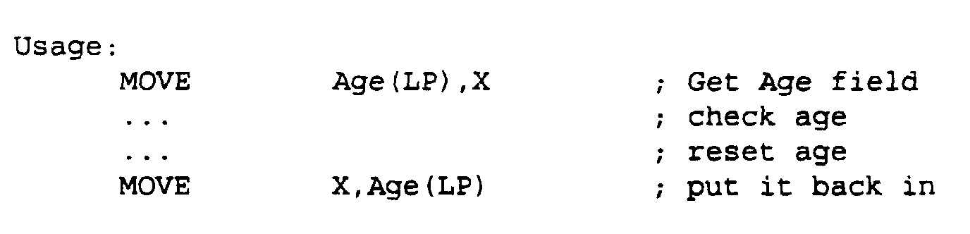
- X,Y Registers 53, 54 are general purpose registers where logic manipulations can be made (AND, OR, XOR). They are used for setting and clearing bits in certain words in the SIB RAM (eg. Age bit) and to test for certain bits (eg. status bits).
- the X Register 53 can be selected as Operand A to the Logic Unit while the Y Register can be selected as Operand B.
- the Y Register 54 is the only register source for moves to the result FIFOs.
- the X Register 53 can be saved to or restored from X' Registers (X'0-X'7) 55.
- the mnemonic symbol for the currently selected X' register is XP.
- the S Register 56 is a pipelining stage between SIB RAM 20 and the Logic Unit. It simplifies read access from SIB RAM 20 by relaxing propagation delay requirements from SIB RAM 20 valid to register setup. It provides the added advantage of essentially caching the most recent SIB RAM access for repeated use. It is loaded by the GET Index(LP) instruction.
- the LEC 3 controls the operation of the look-up engine. All look-up requests pass through the LEC 3, which in turn activates the SALE 2 and the DALE 5 as required.
- the LEC 3 is microcode based, running from a 32-bit wide microcode RAM.
- the instruction set consists mainly of compare-and-branch instructions, which can be used to find specific bit patterns or to check for valid ranges in packet fields. Special I/O instructions give the LEC random read access to the interface RAM.
- the LEC has access to 3 memory systems: the interface RAM 9, the SIB RAM 20 and the Microcode RAM 22.
- the interface RAM 9 is used to feed packet data into the LEC 3.
- the look-up engine hosts dump packet headers into this RAM through snoop FIFOs 42, 43. This RAM is only accessible through the snooped buses.
- the SIB RAM 20 is used to hold information for each known end-station.
- the LEC 3 can arbitrarily retrieve data from this RAM and transfer it to one of the response FIFOs 11, 12 or to internal registers for manipulation and checking.
- High speed RAM is also used to minimize the data retrieval time.
- the size of the SIB RAM 20 is dependent on the maximum number of reachable end-stations. For a limit of 8,000 end-stations, the SIB RAM size is 256K bytes. This RAM is accessible directly to the Control Processor for updates.
- the Microcode RAM 22 is dedicated to the LEC 3. It contains the 32 bit microcode instructions.
- the LEC 3 has read-only access to this high speed RAM normally, but it is mapped directly to the Control Processor's memory space at startup for microcode downloading.
- Variable fields of a packet are searched in one of many search trees in the ALEs 1, 2, ( Figure 5), which are nibble index machines.
- Each ALE 1, 2 has its own search tree RAM 6, 8 ( Figure 7), which is typically high density but low speed. This RAM is divided into 32 byte blocks which can either be Index Arrays or Information Blocks.
- the searches in the ALEs 1, 2 are based strictly on the root pointer, the search key and search key length it is given.
- a look at the look-up engine memory map ( Figure 7) as viewed from the ALEs shows how the mechanism works.
- All search trees in a given ALE 6, 8 reside in the upper half of its memory.
- the 16-bit root pointer given to the ALE will have the most significant bit set.
- the search key (eg. MAC address) is divided into nibbles. The first nibble is concatenated with the root pointer to get an index into the root pointer array. The word at this location is retrieved. If the MSB (Most Significant Bit) (P Bit) is set, the next nibble is concatenated with the retrieved word to form the next pointer. If the P Bit is clear, the search is finished. The final result is given to the LEC, which uses it either as a pointer into the SIB RAM, or as data, depending on the context of the search. A zero value is reserved as a null pointer value.
- Figure 8 illustrates search tree operation.
- the search key length limits the number of iterations to a known maximum.
- the control processor manipulating the search tree structure may choose to shorten the search by putting data with a zero P bit at any point in the tree.
- Figure 9 is a diagram illustrating a MAC search tree example.
- the main purpose of the ALE RAMs 6, 8 is to hold MAC layer addresses.
- the amount of memory required, given 32-byte pointer arrays, is 32N.
- the number obtained from this formula can be quite huge, especially for MAC addresses, but some rationalizations can be made.
- the first 6 nibbles of the address is the Organizationally Unique Identifier (OUI), which is common to Ethernet cards from the same manufacturer. It can be assumed that a particular system will only have a small number of different OUIs.
- OUI Organizationally Unique Identifier
- IP IP
- IP network will not have very many subnets and even fewer network numbers.
- ALE 1, 2 is capable of holding any arbitrary search tree.
- Network layer addresses, intra-area filters, and user-defined MAC protocol types can all be stored in search trees. The decision to put a search tree in either SALE or DALE is implementation dependent; it relies on what searches can be done in parallel for maximum speed.
- the principal function of the SALE 2 is to keep track of the MAC addresses of all stations that are locally attached to the bridge-router. Typically one station will be attached to a bridge-router port, but connections to traditional hubs, repeaters and bridge-routers are allowed, so more source addresses will be encountered.
- RAM calculations for the source address trees are as follows: Number of OUIs Number of Stations Total Bytes 20 400 65,440 2 500 65,184 20 500 77,984 20 800 116,284 5 1,000 131,552
- the number of source stations is limited to some fraction of the total allowable stations. The limit is imposed here because the SALE will most likely hold many of the other search trees (eg. per protocol NL address search trees, intra-area filters).
- the SALE 1 Whenever a new source address is encountered, the SALE 1 will not find it in the MAC source address search tree.
- the LEC 3 realizes the fact and sends it to the Control Processor.
- the new source address is inserted into the search tree once validation is received from the Route Server.
- the Age entry in the SIB 20 is refreshed by the LEC 3.
- the control processor clears the Age entry of all source addresses every aging period. The entry is removed when the age limit is exceeded.
- the source address look-up engine table is shown in Figure 11.
- the DALE 1 keeps track of all stations that are directly reachable from the bridge-router, including those that are locally attached.
- the DALE search trees are considerably larger because they contain MAC addresses of up to 8,000 stations.
- Typical memory sizes for MAC destination address search trees would be: Number of OUIs Number of Stations Total Bytes 10 8,000 856,992 20 8,000 945,824 30 8,000 1,034,464
- a station's MAC address will appear in the MAC search tree if the station is reachable through MAC bridging.
- a station's network layer address will appear in the corresponding network layer search tree if it is reachable through routing.
- the destination address look-up engine MAC table is shown in Figure 12.
- IP masking may be required if a particular port is known to have a router attached to it. Masking is achieved by configuring the IP network layer search tree in such a way that the node portion of the address is treated as Don't Care bits and the corresponding pointers point to the same Next Index Array.
- the SALE and DALE RAMs 8, 6 are divided up into 16 word blocks. These RAMs are accessible only to the corresponding ALE and the Control Processor. These RAMs contain mostly pointer arrays organized in several search trees.
- the SIB RAM 20 is divided into 16 word blocks which can be treated as records with 16 fields. Each block typically contains information about an endstation. This RAM is accessible only to the LEC and the CP.
- the LEC 3 uses the lookup pointer (LP) as a base pointer into a SIB 20.
- the contents of the LP is obtained either from the result of a SALE 2 or DALE 1 search to access end-station information, or from a constant loaded in by the microcode to access miscellaneous information (eg. port information).
- the LP provides the upper sixteen bits and the microcode word provides the lowest four bits of the SIB RAM address.
- the SIB RAM 20 ( Figure 14) generally contains information about the location of an endstation and how to reach it.
- the PortSet field may keep track of the port that the endstation is attached to (if it is locally attached) and the connection index refers to a VPI/VCI pipe to the endstation (if it is remotely attached).
- Other fields are freely definable for other things such as protocol filters, source and destination encapsulation types and quality-of-service parameters, as the need arises.
- PIB Port Information Block
- Figure 15 A variant of the SIB is the Port Information Block (PIB) ( Figure 15).
- PIBs contain information about a particular port. Certain protocols have attributes attached to the port itself, rather than the endstations. An endstation inherits the characteristics assigned to the port to which it is attached.
- the definition of the SIB is flexible; the only requirement is that the data be easily digestible by the LUE instruction set.
- the field type can be a single bit, a nibble, a byte, or a whole word.
- the CI Connection Identifier
- the CI Connection Identifier field is a reference to an ATM connection to the endstation if it is remotely attached. This field is zero for a locally attached endstation.
- the PortSet field is used both for determining the destination port of a locally attached endstation, and for determining whether a source endstation has moved.
- a moved endstation must go through a readmission procedure to preserve the integrity of the network. This field is zero for a remotely attached endstation.
- the MAC Index is a reference to the 6-byte MAC layer address of the endstation. This field is used for network layer forwarded packets, which have the MAC layer encapsulation removed.
- the MAC layer address is re-attached when a packet is re-encapsulated before retransmission out an Ethernet port.
- the encapsulation flags determine the MAC re-encapsulation format.
- the Proto Area and Proto Dest Area fields are used for filtering operations. Because the Newbridge-router system essentially removes the traditional physical constraints on a network topology, the area concept logically re-imposes the constraints to allow existing protocols to function properly. Filtering rules defined between areas determine whether two endstations are logically allowed to communicate with each other using a specific protocol.
- the Proto Area field is a pointer to a filtering rule tree, which is similar in structure to the address trees.
- the Dest Area field is a search key into the tree.
- the result of the search is a bitfield in which each protocol is assigned one bit. Communications is allowed if the corresponding bit is set.
- Figure 16 shows a filtering rule tree
- the microcode for the LEC 3 will now be described.
- the LEC microcode is divided into four main fields as shown in the table below. The usage of each field is dependent on the instruction group.
- the instruction group field consists of instructions grouped according to similarity of function. A maximum of eight instruction groups can be defined.
- the Instruction field definition is dependent on Instruction Group.
- Displacement field is added to the PC if the branch condition is true. This field is used by non-branch instructions for other purposes.
- the FIFO write instructions are used to write data into the currently active result FIFO.
- the third instruction in the list is a direct memory access from SIB RAM to the active FIFO.
- SIB RAM is enabled while the active FIFO is sent a write pulse. Doing so avoids having SIB data propagate through the LUE.
- Bit 20 differentiates between a DMA and a non-DMA instruction.
- the X register cannot be used as a MOVEF source because what would normally be the ASel field conflicts with the Extra field.
- Interface RAM Data Read instructions are used to read data from the Interface RAM 41 into the X, Y or LP Register.
- the LP used is preselected using the RSEL instruction.
- Lookup Pointer instructions are used to load the Lookup Pointers or to store and retrieve values in Lookup RAM.
- Increment Branch instructions are used to compare the current packet field with an immediate value. If the condition is met, the branch is taken; otherwise IP is incremented by the Increment Size.
- X Register Branch instructions are derived from the X Register Logic instructions with Operand A always set to the X Register and Operand B always set to the Immediate value.
- the X Register is not affected by any of these instructions.
- the displacement field is reduced to 5 bits (+/- 32 instructions)
- Index Pointer instructions are used to perform manipulations on the index pointer.
- Transfers from the X registers are not normally used in a lookup function but may be useful for general purpose transfers from interface RAM.
- the Register Select instruction selects a register from each of the register banks.
- the format of the Bank Select Bits field is:
- the En bits determine whether the corresponding select bits are valid. If En is zero, the corresponding register selection remains unchanged. If En is one, the corresponding select bits are used. This mechanism allows register selections to be made independent of each other.
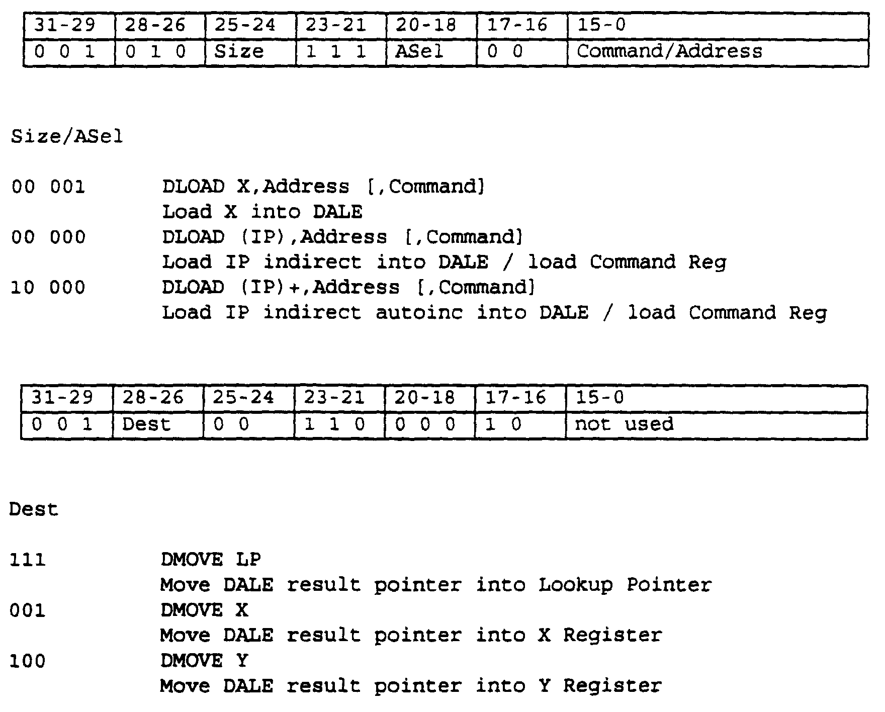
- the destination lookup instructions set up the DALE and read results from it.
- the currently selected lookup pointer is used as the root pointer.
- the DLOAD instruction loads words into the 16 by 16 bit DALE Nibble RAM and loads the Command Register.
- the DMOVE instruction returns the DALE result.
- the Start bit signals the DALE to start the lookup.
- the Nibble Offset field points to the first valid nibble in the first word loaded into the Address RAM.
- the Address field points to the word being written in Nibble RAM.
- the DMOVE instruction gets the 16 bit DALE result pointer. DMOVE should be preceded by DWAIT, otherwise the result may be invalid.
- the destination lookup instructions set up the SALE and read results from it.
- the currently selected lookup pointer is used as the root pointer.
- the SLOAD instruction loads words into the 16 by 16 bit SALE Nibble RAM and loads the Command Word.
- the SMOVE instruction returns the SALE result.
- the Start bit signals the SALE to start the lookup.
- the Nibble Offset field points to the first valid nibble in the first word loaded into the Address RAM.
- the Address field points to the word being written in Address RAM.
- the SMOVE instruction gets the 16 bit SALE result pointer.
- the SMOVE instruction should be preceded by SWAIT, otherwise the result may be invalid.
- the CLOAD instruction loads a word count into the checksum engine, clears the checksum and starts the engine.
- the word currently indexed by IP is subsequently added to the checksum each time the IP crosses a word boundary until the count is exhausted.
- ISM instruction State Machine
- a lookup engine microcode will typically take four clock cycles. At 50 MHz, the instruction cycle takes 80 ns to execute. Instructions that require access to SIB RAM, which require arbitration with the Control Processor, and any future extensions that require more time to execute will require one or more additional cycles to complete.
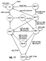
- the 3 LEC After reset, the 3 LEC is in the idle state. As soon as one of the snoop FIFOs 42, 43 is non-empty, the ISM enters the main instruction cycle loop.
- a microcode instruction cycle is typically divided into four main states. State 3 and State 0 allow the microcode contents to propagate through the LEC.
- the instruction group is determined in State 1. If a fast instruction is being executed (Groups 0-3), State 2 is entered immediately. Otherwise the appropriate next state is entered according to the Group field.
- Figure 18 shows a typical fast instruction.
- State 42 is a dummy state for currently undefined groups.
- State 52 is a wait state for external accesses to SIB RAM.
- the ISM exits this state when the SIB RAM has been granted to the LEC long enough for an access to complete.
- Figure 19 shows a typical SIB RAM access instruction.
- States 72 and 73 are executed during the STOP instruction. State 73 flushes the snoop FIFOs in case
- the LEC cycles through States 0 to 3 indefinitely until a STOP instruction is encountered, which brings the LEC back to the idle state.
- the lookup request mechanism for a MAC layer lookup is as follows:
- Packets are discarded if they serve no other useful purpose (eg. SA and DA on the same port or in different areas, errored packets). Otherwise they are sent to the Control Processor for further processing.
- the described look-up engine is capable of performing bridge-router and most network layer look-ups in less than 5.6 ⁇ s (1/178,000) with to minimum RAM requirements and cost and maximizes flexibility for future additions/corrections without hardware changes.
- the intended application of the look-up engine is high performance LAN systems and other packet-based devices.
Landscapes
- Engineering & Computer Science (AREA)
- Computer Networks & Wireless Communication (AREA)
- Signal Processing (AREA)
- Data Exchanges In Wide-Area Networks (AREA)
- Small-Scale Networks (AREA)
- Information Retrieval, Db Structures And Fs Structures Therefor (AREA)
- Computer And Data Communications (AREA)
Description
- This invention relates to the field of data communications, and more particularly to packet-based networks.
- There are two broad classes of network: circuit-based and packet-based. Conventional telephone networks are circuit based. When a call is established in a circuit-based network, a hard-wired connection is set up between the calling parties and remains in place for the duration of the call. Circuit-based networks are wasteful of available bandwidth and lack flexibility.
- Packet-based networks overcome many of the disadvantages of circuit-based networks. In a packet-based network, the data are assembled into packets containing one or more address fields which define the context of a packet, such as protocol type and relative positions of other fields embedded in the packet. LAN bridges and routers use the information in the packet to forward it to the destination.
- In a packet-based network, a packet must be parsed as it flows through the network. Parsing is the process of extracting and analyzing the information, such as source and destination address and net layer protocol, contained in the packets.
- In known networks, packet parsing is generally performed with a microprocessor, which provides flexibility in handling different packet types and can be upgraded to handle new packet types as they are defined. Content Addressable Memory (CAM) is commonly used for hardware assistance to speed up searches through a list of known addresses. This is a tedious task. CAMs are also relatively expensive and limited in size and availability.
- General purpose processor architectures are not specifically directed toward the types of operations required in packet parsing and so they tend to be inefficient. To meet performance requirements, a fast but expensive processor based solution can be implemented. In the highest performance systems, hardware solutions are implemented to increase speed, but at the cost of flexibility. By way of example, US patent no. 5,095,480 discloses a message routing system that employs routing tables to determine the path to the destination address.
- US patent no. 5,088,090 discloses a transmission system consisting of local area networks interconnected by bridges. At each bridge, packets are filtered to determine whether they have a destination address on an attached LAN by comparing their MAC addresses with addressed in a look-up table. The patent is silent as to the nature of the look-up process. The patent also discusses the spanning tree protocol for identifying a path through the network.
- An object of the invention is to provide a fast, but inexpensive solution to the problem of packet-parsing in packet-based networks.
- According to the present invention there is provided an arrangement for parsing packets in a packet-based data transmission network, said packets including packet headers divided into fields having values representing information pertaining to the packet, said arrangement comprising an input for receiving fields from said packet headers of incoming packets, a memory for storing information related to possible values of said fields, and a look-up engine for retrieving said stored information appropriate to a received field value. The look-up engine includes at least one said memory containing said stored information organized in a hierarchical tree structure, and a microcode controller for controlling the operation of said look-up engine while performing bit pattern recognition on at least a portion of the packet.
- The memory and retrieving means constitute a look-up engine, which is the central resource containing all information necessary for forwarding decisions.
- In a packetized data transmission conforming to IEEE802 standards, the packets have a MAC (medium access control) header containing information about the destination and source addresses and the net layer protocol. The invention permits packet switching to be achieved in a bridge-router, for example an Ethernet to ATM bridge-router, at a rate of about 178,000 packets per second using 64 byte minimum Ethernet packets. This means that the MAC headers are interpreted once every 5.6 micro seconds.
- The look-up engine preferably employs table look-ups using nibble indexing on variable portions of the packet, such as MAC and network layer addresses, and bit pattern recognition on fixed portions for network layer protocol determination.
- Each look-up table is organized into a hexadecimal search tree. Each search tree begins with a 16 word root table. The search key (e.g. MAC address) is divided into nibbles which are used as indices to subsequent tables. The 16 bit entry in the table is concatenated with the next 4 bit nibble to form the 20 bit address of the next 16 word table. The final leaf entries point to the desired information.
- Bit pattern recognition is achieved by a microcode instruction set. The microcode engine has the ability to compare fields in a packet to preprogrammed constants and perform branches and index increments in a single instruction cycle typically. The microcode engine has complete control over the search procedure, so it can be tailored to specific look-up functions. New microcode is downloaded as new functions are required.
- The look-up engine can perform up to two tree searches in parallel with microcode execution. Look-up time is quick because the microcode determines the packet's network layer format while the source and destination addresses are being searched in parallel. The results of the source and destination look-ups and the protocol determination arrive at roughly the same time, at which point the next level of decisions is made.
- The look-up engine also performs protocol filtering between areas. The system allows devices to be grouped arbitrarily into areas on a per protocol basis and defines filtering rules among these areas. The look-up engine keeps track of each station's area for each of its protocols. The source and destination areas are cross-indexed in a search tree, which is used to find the filtering rule between the two areas. Separate filtering rules are defined for bridging and network layer forwarding; bridging is normally allowed within an area while network layer forwarding is selectively allowed between areas.
- The parsing controller typically has a pointer to the current field in the packet being examined. The controller moves this pointer to the next field in the packet after all decisions based on the current field are made.
- At each decision point on a tree, the current field is compared to a known value or range. If the comparison yields a true condition, the controller moves to the next decision point by moving the current field pointer. Otherwise the field pointer is left alone and controller branches to new code to compare the current field to a different value or range. This process is repeated until a final decision is made.
- Moving to the next decision point requires several discrete steps in a general purpose processor. Unlike a general purpose processor, which has the disadvantage that it only has a single memory bus for both instruction and data fetches, the Look-up engine controller has separate buses for instruction and data and typically performs one decision per step. Fast decisions are made possible by a special set of instructions which both conditionally move the pointer and conditionally branch to new code in a single step. The comparisons and pointer movements can be byte or word wide, according to the current field's size.
- The look-up engine implements other optimized instructions which perform bit level logical comparisons and conditional branches within the same cycle as well as other instructions tailored to retrieving data from nibble-indexed data structures.
- The look-up engine is preferably divided into the following sections:
- a) one or more nibble tree address look-up engines (ALE)
- b) one microcode engine
-
- Each ALE is used to search for addresses in a tree structure in its own large bank of memory. The result of a search is a pointer to pertinent information about the address. An ALE is assigned to destination addresses (DALE) and source addresses (SALE). The ALEs operate independently of each other.
- The microcode engine is used to coordinate the search. It invokes the SALE and DALE to search for the source and destination addresses respectively and continues on to parse the remainder of the packet using an application-specific instruction set to determine the protocol.
- The SALE, DALE and microcode engine can execute in parallel and arrive at their corresponding results at roughly the same time. The microcode engine then uses the SALE and DALE results along with its own to arrive at the forwarding decision.
- The advantage of using RAM over a CAM is expandability and cost. Increasing RAM is a trivial and inexpensive task compared to increasing CAM size.
- The advantage of the microcode engine over a general purpose processor is that an ASIC implementation of the function is much less expensive and less complex than a processor-based design with all the overhead (RAM, ROM) associated with it.
- The invention also provides a method of parsing packets in a packet-based data transmission network, said packets including packet headers divided into fields having values representing information pertaining to the packet, comprising storing information related to possible values of said fields, receiving fields from said packet headers of incoming packets, and retrieving by means of a look-up engine said stored information appropriate to a received field value, characterized in that said information is retrieved from a memory organized in a hierarchical tree structure under the control of a microcode controller while said microcode controller performs bit pattern recognition on at least a portion of the packet.
- The invention will now be described in more detail, by way of example only, with reference to the accompanying drawings, in which:-
- Figure 1 is an example of a MAC layer header of a typical packet;
- Figure 2 shows the data paths in a typical bridge-router between Ethernet LAN and ATM networks;
- Figure 3 is a block diagram of a first embodiment of a look-up engine in accordance with the invention;
- Figure 4 is a block diagram of a look-up engine controller for the look-up engine shown in Figure 3;
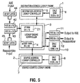
- Figure 5 is a block diagram of a second embodiment of a look-up engine in accordance with the invention;
- Figure 6 is a block diagram of a look-up engine controller for the look-up engine shown in Figure 5;
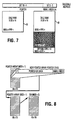
- Figure 7 is a map of look-up engine Address Look-up engine (ALE) memories;
- Figure 8 is a diagram illustrating search tree operation in an ALE;
- Figure 9 shows one example of a MAC search tree;
- Figure 10 shows the effect of the organizationally unique identifier of the MAC addresses on the size of the search tree;
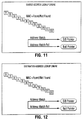
- Figure 11 shows the source address look-up engine table;
- Figure 12 shows the destination address look-up table;
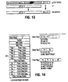
- Figure 13 illustrates the look-up engine addressing modes;
- Figure 14 shows a station information block;
- Figure 15 shows a port information block;
- Figure 16 shows an example of protocol filtering;
- Figure 17 shows a look-up engine controller Instruction State Machine;
- Figure 18 shows a typical fast timing diagram; and
- Figure 19 shows a typical SIB RAM access instruction timing diagram.
-
- A typical look-up engine (LUE) in accordance with the invention is designed to be used in a twelve-port wire speed Ethernet to ATM bridge-router capable of switching about 178,000 packets per second using 64 byte minimum Ethernet packets. This packet rate corresponds to a look-up request occurring every 5.6 µsecs. The LUE is used each time a packet is received off the Ethernet or the ATM network. The type of information that the engine provides depends on the direction of packet flow and the type of packet.
- The look-up engine provides all the information needed to find the path to each known destination, as well as default information in the case of unknown destinations.
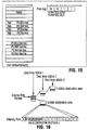
- Figure 1 shows a typical MAC layer header format for a packet that can be parsed with the aid of the look-up engine in accordance with the invention. The header comprises destination and source address fields 100, 101, a network layer
protocol type field 102, and network layer destination and source address fields 103, 104. Figure 1 also illustrates how the header is parsed in accordance with the invention. All fields except 102 are parsed using a tree search. The Net LayerProtocol Type field 102 is parsed by using microcode comparisons in the microcode engine to be described. - On a bridge-router, each port is represented by a corresponding bit in a PortSet (Ports 0-11), which is a 16 bit value that has local significance only. The Control Processor and ATM are each assigned a port.
- The following definitions are special cases of a PortSet:
- SinglePortSet
- a PortSet with a single bit set.
- HostPortSet
- a SinglePortSet corresponding to the control Processor
- MyPortset
- a SinglePortSet corresponding to the source port of this packet.
- NullPortSet
- a Portset of no ports.
-
- A Connection Identifier (CI), which is a 16 bit value with local significance only, is used to map connections into VPI/VCI values.
- The following definitions are special cases of CI:
- Mesh_CI
- a CI corresponding to a path towards the destination endstation's Bridge-router.
- Null_CI
- a CI connected to nothing. It is returned when the destination is attached to the local Bridge-router or if the connection is not allowed.
- RS_CI
- a CI corresponding to a path to the Route Server.
- ABS_CI
- a CI corresponding to a path to the Address/Broadcast Server.
-
- MAC layer addresses are globally unique 48 bit values, except in some protocols such as DECNet, where they may not be globally unique.
- Unicast_DA
- a MAC layer destination address of an end-station.
- Router_DA
- a MAC layer destination address of the Route Server. An endstation sends packets to the Route Server when it cannot send to the destination directly at the MAC layer.
- Broadcast_DA
- the broadcast MAC layer address (all ones) which is received by all end-stations. It cannot be a source address.
- Multicast_DA
- a multicast MAC layer address (group bit set) which is received by end-stations that recognize that multicast address.
-
- Network layer (NL) addresses are network protocol dependent. They are generally divided into Network, Subnet, and Node portions, although not all protocols have all three present. The Network Layer Address Field Sizes (in bits) are summarized in the table below.

- The look-up engine handles unicast network layer addresses.
- When the look-up engine is used in a bridge-router providing an interface between an Ethernet and ATM network, packets coming from the Ethernet side are fed into the Look-up Engine. The result of the look-up has the form:
- Input -> Command, CI, PortSet where Input is derived from the first few bytes of the packet and Command is an opcode to the AXE (Transfer engine).
-
- The Quad MAC status word distinguishes between router MAC, broadcast and multicast MACs.
- Bridging occurs when the destination address is a unicast address other than the Route Server address. Bridging is allowed between two endstations in the same area for a given protocol.
- Both source and destination MAC addresses must be known before automatic bridging/filtering is performed; otherwise, the packet is sent to the Route Server for:
- SA (Source Address) validation if the SA has never been seen speaking a given protocol
- DA (Destination Address) resolution if the DA was not found in the local MAC cache.
- The Bridge command instructs the AXE (Transfer Engine) to use RFC-1483 bridge encapsulation. BridgeProp command instructs the AXE to use bridge-router encapsulation (include source PortSet in encapsulation)
- Unknown_SA -> BridgeProp, Null_CI, HostPortSet, MyPortSet
- Unknown SA - send to HP for Spanning Tree processing
- HP will decide whether to forward it to ABS for learning, depending on Spanning Tree state
- Unicast_DA -> Bridge, Mesh_CI, NullPortSet
- DA in the same area on a different Bridge-router
- Unicast_DA -> Bridge, Null_CI, NullPortSet
- DA not in the same area (reject)
- Protocol not allowed to bridge-router
- DA on the same port
- Unicast_DA -> Bridge, Null_CI, SinglePortSet
- DA in the same area on the same Bridge-router but on a different port
- Unknown_DA -> BridgeProp, ABS_CI, NullPortSet, MyPortSet
- DA not found in the table - send to ABS for flood processing Broadcast_DA -> BridgeProp, ABS_CI, NullPortSet, MyPortSet
- Broadcast DA - Send to Control Processor for broadcast processing
- Multicast_DA -> BridgeProp, ABS_CI, NullPortSet, MyPortSet
- Multicast DA - Send to ABS for multicast processing
- Multicast_DA -> BridgeProp, Null_CI, HostPortSet, MyPortSet
- Multicast DA is of interest to HP (eg Spanning Tree)
- HP will decide whether to forward it to ABS for multicast processing
-
- Routing occurs when the destination address is the unicast Route Server address. Filtering rules between areas are explicitly defined per protocol. The per protocol source area is an attribute of the source MAC address and the per protocol destination area is an attribute of the destination NL address.
- Both source MAC and destination NL addresses must be known before network layer forwarding can occur.
- The packet will be bridged to the Route Server if any of the following are true:
- IP options are present
- Protocol is unknown
- The packet will be dropped if any of the following are true:
- Source area is not allowed to send to Destination area for this protocol
- Source NL address is invalid (eg. any IP broadcast address)
- Checksum is invalid
- Time-To-Live field expires
- Unicast_NLDA -> Route, Mesh_CI, NullPortSet
- NL node on a different bridge-router
- Unicast_NLDA -> Route, Null_CI, SinglePortSet
- NL node on the same bridge-router (could be same port)
- Unknown_NLDA -> Bridge, RS_CI, NullPortSet
- unknown NL node - send to Route Server
- Unknown_Protocol -> Bridge, RS_CI, NullPortSet
- protocol unknown, or packet with options
- Figure 2 shows the data paths in a typical bridge-router.
Control processor 16 has control over the formatting of packets it sends and receives. If thecontrol processor 16 wants look-upengine 17 to perform a look-up, it formats the packet in the same way asQuad Mac 15; otherwise it sends it as a raw packet, which does not require a lengthy look-up. The control processor predetermines the destination by providing a CI (Connection Identifier) and an output Portset as part of the data stream. A bit in the Quad MAC status word indicates a raw packet and the look-up engine simply retrieves the CI and Portset as part of the data stream. A bit in the Quad MAC status word indicates a raw packet and the look-up engine simply retrieves the CI and Portset from the data stream and feeds it to the AXE (Transfer Engine) through the result FIFO. The Control processor is responsible for correctly formatting the required encapsulation. - As shown in Figure 2, packets coming from the ATM side are fed into the look-up engine. The look-up engine accepts an RFC-1483 encapsulated packet and determines whether to look at a MAC or NL address. The result of the look-up will have the form:
- Input -> PortSet
-
- Filtering is not performed in this direction. It is assumed that the all filtering is done at the ingress side. It is also assumed that the destination endstation is known to be attached to the receiving Bridge-router, so unicast packets with unknown destination addresses are dropped.
- Flood and broadcast packets are encapsulated in a special format which includes an explicit output PortSet.
- Unicast_DA -> SinglePortSet
- DA on this Bridge-router
- Unknown_DA -> NullPortSet
- DA not in the table (drop) - this situation should not occur.
- Unicast_NLDA -> SinglePortSet
- NLDA on this Bridge-router
- Unknown_NLDA -> NullPortSet
- NLDA not in the table (drop) - this situation should not occur.
- Broadcast_DA,PortSet -> PortSet
- Proprietary Broadcast request received from RS
- Multicast_DA,PortSet -> PortSet
- Proprietary Multicast request received from RS
- Unknown_DA,PortSet -> PortSet
- Proprietary Flood request received from RS
-
- Turning now to Figure 3, the look-up engine consists of three functional blocks, namely a destination address look-up engine (DALE) 1, a source address look-up engine (SALE) 2, and a look-up engine controller (LEC) 3, which includes a
microcode ram 4.DALE 1 includes a destination address look-upcontroller 5 andDALE RAM 6.SALE 2 includes a source address look-upcontroller 7 andSALE RAM 8. The input to the look-up engine is through a fast 16-bit wide I/F RAM 9 receiving input from the AXE (Transfer Engine) and re-assembler. The output from the look-up engine is through word-wide FIFOs - One embodiment of look-up engine controller (LEC) 3 is shown in more detail in Figure 4. This comprises (Station Information Block)
SIB ram 20,interface ram 21, and microcode ram 22. TheSIB ram 20 is connected to look-uppointers 23.Interface ram 21 is connected to data register 25 andindex pointers 26 connected to ALU (Arithmetic Logic Unit) 27. Microcode ram 22 is connected to instruction register 28. - The look-up
Engine controller 3 is a microcoded engine tailored for efficient bit pattern comparisons through a packet. It communicates with the Source Address Look-upEngine 2 and the Destination Address Look-upEngine 1, which both act as co-processors to theLEC 3. - The look-up engine snoops on the receive and transmit data buses and deposits the header portion of the packet into the I/
F RAM 9. The look-up response is sent to theappropriate FIFO - Figures 5 show an alternative embodiment of the loop-up engine and controller. In Figure 5, the
LEC 3 includes a 64 x 16 I/F (Interface) ram 41 connected to FIFO's 42, 43 (First-in, First-out memories) respectively connected to latches 44, 45 receiving AXE (Transfer Engine) and reassembler input. - Referring now to Figure 6, the
LEC 3 also contains several registers, which will now be described. Register select instructions are provided for the register banks (XP0-7, LP0-7). - Index Pointer register (IP) 50 is a byte index into the I/
F RAM 21. Under normal operation, theindex pointer register 50 points to the current packet field being examined in the I/F RAM 21 but it can be used whenever random access to the I/F RAM 21 is required. - The
IP 50 can be modified in one of the following ways: - 1) loaded by the LOADIP instruction (eg. to point to the beginning of the packet)
- 2) incremented by 1 (byte compare) or 2 (word compare) if a branch condition is not met.
- 3) incremented by 2 by a MOVE (IP)+ type instruction.
-
-
Data Register 51 contains the 16 bit value read from I/F RAM 21 using the current IP. TheDR 51 acts like a one word cache; the LEC keeps its contents valid at all times. -
Program Counter 52 points to the current microcode instruction. It is incremented by one if a branch condition is true, otherwise the displacement field is added to it. - The Lookup Pointers (LP0-7) 23 are 16 bit registers which contain pointers to the
SIB RAM 20. The LPs are used to store pointers whenever milestones are reached in a search. One LP will typically point to a source SIB and another will point to a destination SIB. The LP provides the upper 16 bits of the pointer; the lower 4 bits are provided by the microcode word for indexing into a given SIB. - The LPs are also used to prime the SALE and DALE with their respective root pointers.
- X,Y Registers 53, 54 are general purpose registers where logic manipulations can be made (AND, OR, XOR). They are used for setting and clearing bits in certain words in the SIB RAM (eg. Age bit) and to test for certain bits (eg. status bits). The
X Register 53 can be selected as Operand A to the Logic Unit while the Y Register can be selected as Operand B. - The BYZ and BYNZ instructions conditionally branch on Y=0 and Y<>0 respectively.
- The
Y Register 54 is the only register source for moves to the result FIFOs. - The
X Register 53 can be saved to or restored from X' Registers (X'0-X'7) 55. The mnemonic symbol for the currently selected X' register is XP. - The
S Register 56 is a pipelining stage betweenSIB RAM 20 and the Logic Unit. It simplifies read access fromSIB RAM 20 by relaxing propagation delay requirements fromSIB RAM 20 valid to register setup. It provides the added advantage of essentially caching the most recent SIB RAM access for repeated use. It is loaded by the GET Index(LP) instruction. - As in Figure 3, the
LEC 3 controls the operation of the look-up engine. All look-up requests pass through theLEC 3, which in turn activates theSALE 2 and theDALE 5 as required. TheLEC 3 is microcode based, running from a 32-bit wide microcode RAM. The instruction set consists mainly of compare-and-branch instructions, which can be used to find specific bit patterns or to check for valid ranges in packet fields. Special I/O instructions give the LEC random read access to the interface RAM. - The LEC has access to 3 memory systems: the
interface RAM 9, theSIB RAM 20 and the Microcode RAM 22. - The
interface RAM 9 is used to feed packet data into theLEC 3. The look-up engine hosts dump packet headers into this RAM through snoopFIFOs - The
SIB RAM 20 is used to hold information for each known end-station. TheLEC 3 can arbitrarily retrieve data from this RAM and transfer it to one of theresponse FIFOs SIB RAM 20 is dependent on the maximum number of reachable end-stations. For a limit of 8,000 end-stations, the SIB RAM size is 256K bytes. This RAM is accessible directly to the Control Processor for updates. - The Microcode RAM 22 is dedicated to the
LEC 3. It contains the 32 bit microcode instructions. TheLEC 3 has read-only access to this high speed RAM normally, but it is mapped directly to the Control Processor's memory space at startup for microcode downloading. - Variable fields of a packet, such as addresses, are searched in one of many search trees in the
ALEs ALE search tree RAM 6, 8 (Figure 7), which is typically high density but low speed. This RAM is divided into 32 byte blocks which can either be Index Arrays or Information Blocks. - The searches in the
ALEs - All search trees in a given
ALE - The search key length limits the number of iterations to a known maximum. The control processor manipulating the search tree structure may choose to shorten the search by putting data with a zero P bit at any point in the tree.
- "Don't Care" fields are also achievable by duplicating appropriate pointers within the same pointer array. Search trees are maintained by the Control Processor, which has direct access to the SALE and
DALE RAMs - Figure 9 is a diagram illustrating a MAC search tree example. The main purpose of the
ALE RAMs - X is the number of addresses
- L is the number of nibbles in the address
- N is the number of pointer arrays
-
- The amount of memory required, given 32-byte pointer arrays, is 32N. The number obtained from this formula can be quite huge, especially for MAC addresses, but some rationalizations can be made.
- In the case of MAC addresses, the first 6 nibbles of the address is the Organizationally Unique Identifier (OUI), which is common to Ethernet cards from the same manufacturer. It can be assumed that a particular system will only have a small number of different OUIs.
- The formula for MACs then becomes:
- M is the number of different OUIs
- Xj is the number of stations in OUIj
-
- Assuming that the addresses are distributed evenly over all OUIs,
- The effect of OUI on Search Tree Size is shown in Figure 10.
- Similar rationalizations can be made with IP and other network layer protocol addresses. An IP network will not have very many subnets and even fewer network numbers.
- Although the
SALE 2 typically holds locally attached source MAC addresses and theDALE 1 typically holds destination MAC addresses, eitherALE - The principal function of the
SALE 2 is to keep track of the MAC addresses of all stations that are locally attached to the bridge-router. Typically one station will be attached to a bridge-router port, but connections to traditional hubs, repeaters and bridge-routers are allowed, so more source addresses will be encountered. - Using the formula for RAM size above, typical RAM calculations for the source address trees are as follows:
Number of OUIs Number of Stations Total Bytes 20 400 65,440 2 500 65,184 20 500 77,984 20 800 116,284 5 1,000 131,552 - The number of source stations is limited to some fraction of the total allowable stations. The limit is imposed here because the SALE will most likely hold many of the other search trees (eg. per protocol NL address search trees, intra-area filters).
- Whenever a new source address is encountered, the
SALE 1 will not find it in the MAC source address search tree. TheLEC 3 realizes the fact and sends it to the Control Processor. The new source address is inserted into the search tree once validation is received from the Route Server. - Whenever a previously learned address is re-encountered, the Age entry in the
SIB 20 is refreshed by theLEC 3. The control processor clears the Age entry of all source addresses every aging period. The entry is removed when the age limit is exceeded. - The source address look-up engine table is shown in Figure 11.
- The
DALE 1 keeps track of all stations that are directly reachable from the bridge-router, including those that are locally attached. The DALE search trees are considerably larger because they contain MAC addresses of up to 8,000 stations. - Typical memory sizes for MAC destination address search trees would be:
Number of OUIs Number of Stations Total Bytes 10 8,000 856,992 20 8,000 945,824 30 8,000 1,034,464 - A station's MAC address will appear in the MAC search tree if the station is reachable through MAC bridging. A station's network layer address will appear in the corresponding network layer search tree if it is reachable through routing.
- The destination address look-up engine MAC table is shown in Figure 12.
- IP masking may be required if a particular port is known to have a router attached to it. Masking is achieved by configuring the IP network layer search tree in such a way that the node portion of the address is treated as Don't Care bits and the corresponding pointers point to the same Next Index Array.
- The SALE and
DALE RAMs - The
SIB RAM 20 is divided into 16 word blocks which can be treated as records with 16 fields. Each block typically contains information about an endstation. This RAM is accessible only to the LEC and the CP. - The
LEC 3 uses the lookup pointer (LP) as a base pointer into aSIB 20. The contents of the LP is obtained either from the result of aSALE 2 orDALE 1 search to access end-station information, or from a constant loaded in by the microcode to access miscellaneous information (eg. port information). The LP provides the upper sixteen bits and the microcode word provides the lowest four bits of the SIB RAM address. - The lookup Engine addressing scheme is shown in Figure 13.
- The SIB RAM 20 (Figure 14) generally contains information about the location of an endstation and how to reach it. For example, the PortSet field may keep track of the port that the endstation is attached to (if it is locally attached) and the connection index refers to a VPI/VCI pipe to the endstation (if it is remotely attached). Other fields are freely definable for other things such as protocol filters, source and destination encapsulation types and quality-of-service parameters, as the need arises.
- A variant of the SIB is the Port Information Block (PIB) (Figure 15). PIBs contain information about a particular port. Certain protocols have attributes attached to the port itself, rather than the endstations. An endstation inherits the characteristics assigned to the port to which it is attached.
- The definition of the SIB is flexible; the only requirement is that the data be easily digestible by the LUE instruction set. The field type can be a single bit, a nibble, a byte, or a whole word.
- In Figure 14, the CI (Connection Identifier) field is a reference to an ATM connection to the endstation if it is remotely attached. This field is zero for a locally attached endstation.
- The PortSet field is used both for determining the destination port of a locally attached endstation, and for determining whether a source endstation has moved. In one Newbridge-router Networks system, a moved endstation must go through a readmission procedure to preserve the integrity of the network. This field is zero for a remotely attached endstation.
- The MAC Index is a reference to the 6-byte MAC layer address of the endstation. This field is used for network layer forwarded packets, which have the MAC layer encapsulation removed. The MAC layer address is re-attached when a packet is re-encapsulated before retransmission out an Ethernet port. The encapsulation flags determine the MAC re-encapsulation format.
- The Proto Area and Proto Dest Area fields are used for filtering operations. Because the Newbridge-router system essentially removes the traditional physical constraints on a network topology, the area concept logically re-imposes the constraints to allow existing protocols to function properly. Filtering rules defined between areas determine whether two endstations are logically allowed to communicate with each other using a specific protocol.
- The Proto Area field is a pointer to a filtering rule tree, which is similar in structure to the address trees. The Dest Area field is a search key into the tree. The result of the search is a bitfield in which each protocol is assigned one bit. Communications is allowed if the corresponding bit is set.
- Figure 16 shows a filtering rule tree.
- The microcode for the
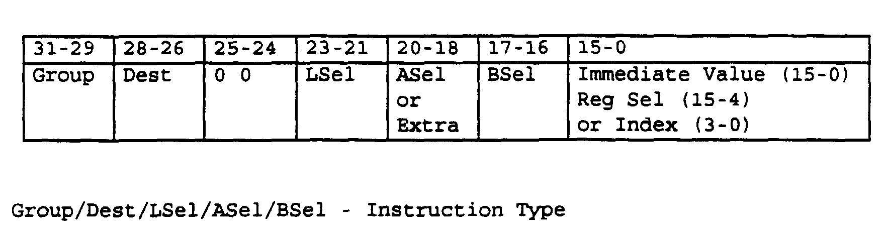
LEC 3 will now be described. The LEC microcode is divided into four main fields as shown in the table below. The usage of each field is dependent on the instruction group.
- The instruction group field consists of instructions grouped according to similarity of function. A maximum of eight instruction groups can be defined.
- The Instruction field definition is dependent on Instruction Group.
- In branch instructions, the Displacement field is added to the PC if the branch condition is true. This field is used by non-branch instructions for other purposes.
- The Parameter field is a 16 bit value used for comparison, as an operand, or as an index, dependent on the instruction.=
- The functions of the groups are set out in the following table.

- The following table describes the use of each of the fields.


-

- The FIFO write instructions are used to write data into the currently active result FIFO. The Extra
field control bits - The third instruction in the list is a direct memory access from SIB RAM to the active FIFO. SIB RAM is enabled while the active FIFO is sent a write pulse. Doing so avoids having SIB data propagate through the LUE.
Bit 20 differentiates between a DMA and a non-DMA instruction. - The X register cannot be used as a MOVEF source because what would normally be the ASel field conflicts with the Extra field.

- Interface RAM Data Read instructions are used to read data from the Interface RAM 41 into the X, Y or LP Register. The LP used is preselected using the RSEL instruction.
-
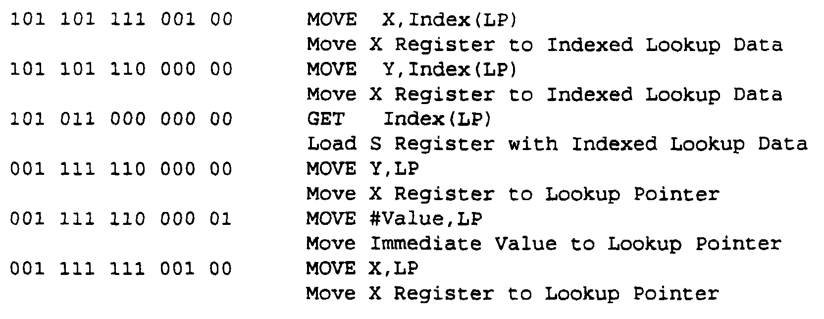
- Lookup Pointer instructions are used to load the Lookup Pointers or to store and retrieve values in Lookup RAM.
-

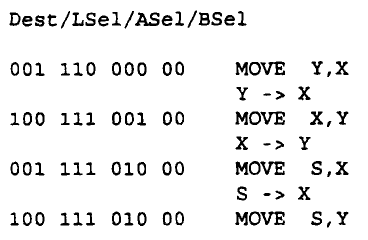
- Logic instructions are used to perform logic manipulations on the X and Y Registers. Combinations of the selections above yield the following (useful) instructions:

-


- Increment Branch instructions are used to compare the current packet field with an immediate value. If the condition is met, the branch is taken; otherwise IP is incremented by the Increment Size.

-

- X Register Branch instructions are derived from the X Register Logic instructions with Operand A always set to the X Register and Operand B always set to the Immediate value. The X Register is not affected by any of these instructions. The displacement field is reduced to 5 bits (+/- 32 instructions)
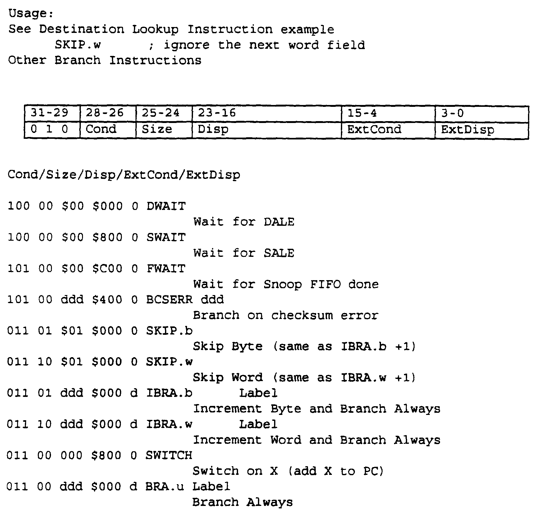
- These instructions are derived from the conditional branch instructions. Wait instructions loop until the extended condition is false. Skip instructions move to the next instruction and increment the IP appropriately.
- More branch instructions can be defined easily by using Cond=100 or 101 and picking an unused ExtCond pattern.
- When Cond = 011 (True), the displacement field is extended to 12 bits.
- The SWITCH instruction adds the least significant nibble of X to the PC. If X(3:0) = 0, 16 is added to the PC.
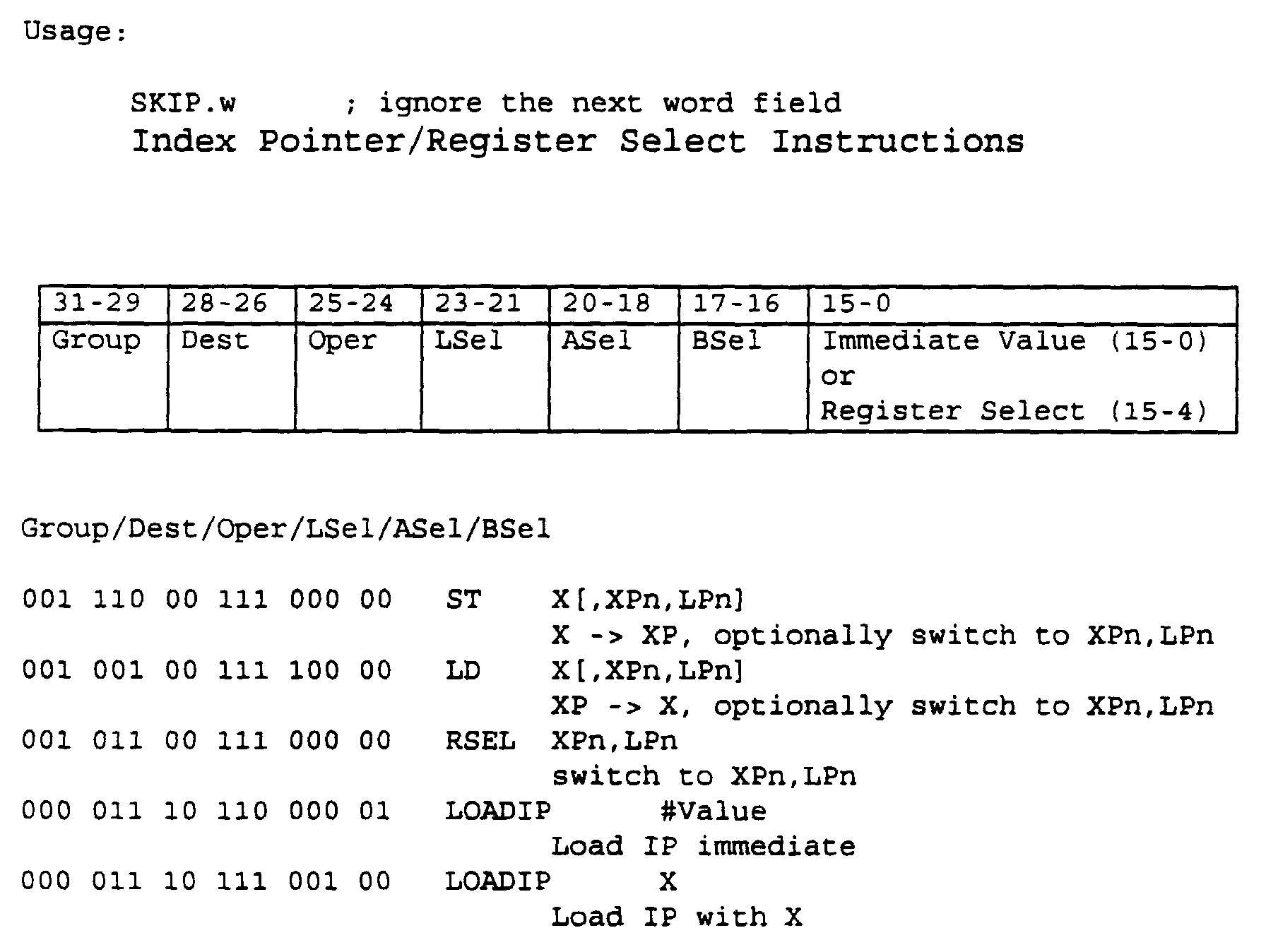
- Index Pointer instructions are used to perform manipulations on the index pointer.
- Transfers from the X registers are not normally used in a lookup function but may be useful for general purpose transfers from interface RAM.
- The Register Select instruction selects a register from each of the register banks. The format of the Bank Select Bits field is:

- The En bits determine whether the corresponding select bits are valid. If En is zero, the corresponding register selection remains unchanged. If En is one, the corresponding select bits are used. This mechanism allows register selections to be made independent of each other.
-
- The destination lookup instructions set up the DALE and read results from it. The currently selected lookup pointer is used as the root pointer.
- The DLOAD instruction loads words into the 16 by 16 bit DALE Nibble RAM and loads the Command Register. The DMOVE instruction returns the DALE result.
-

- The Start bit signals the DALE to start the lookup.
- The Nibble Offset field points to the first valid nibble in the first word loaded into the Address RAM.
- The Address field points to the word being written in Nibble RAM.
- The DMOVE instruction gets the 16 bit DALE result pointer. DMOVE should be preceded by DWAIT, otherwise the result may be invalid.
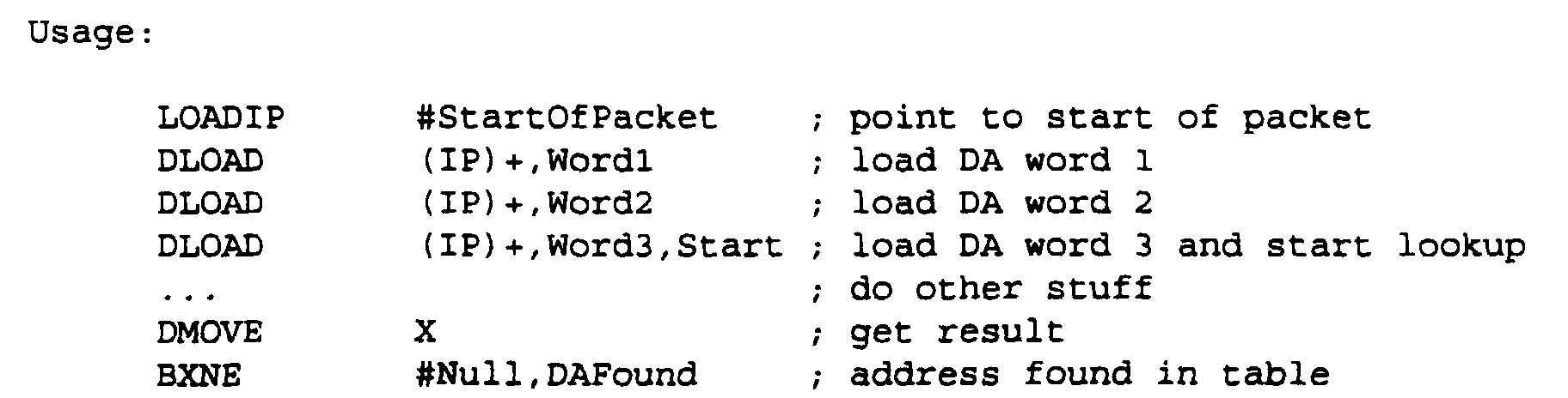
-

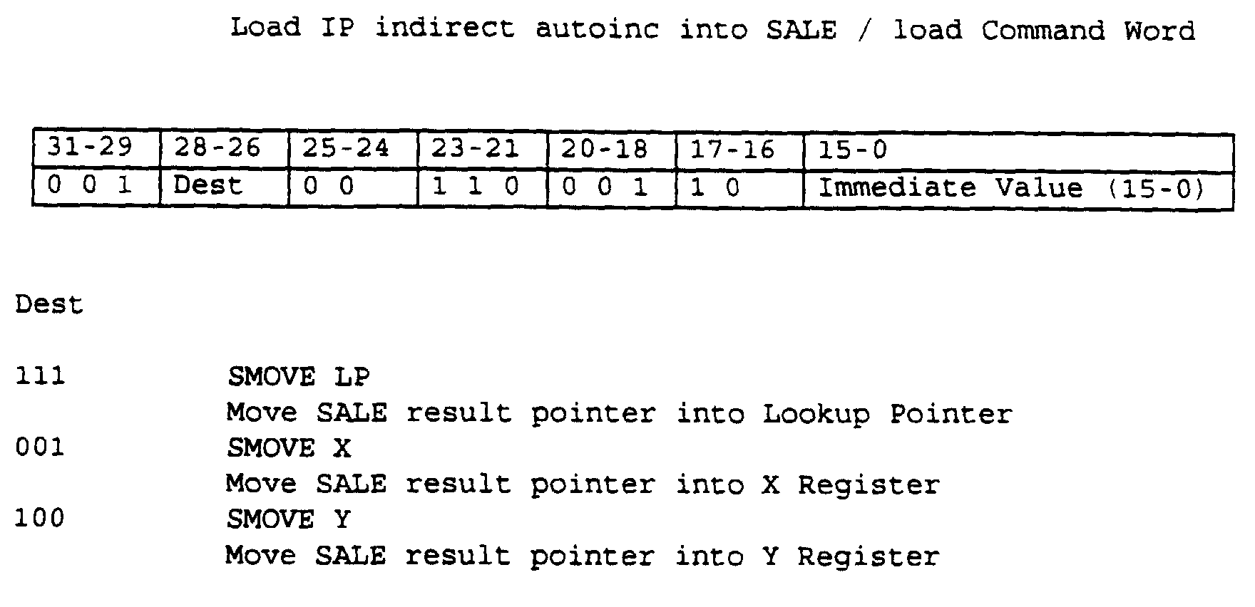
- The destination lookup instructions set up the SALE and read results from it. The currently selected lookup pointer is used as the root pointer.
- The SLOAD instruction loads words into the 16 by 16 bit SALE Nibble RAM and loads the Command Word. The SMOVE instruction returns the SALE result. Command Word

- The Start bit signals the SALE to start the lookup.
- The Nibble Offset field points to the first valid nibble in the first word loaded into the Address RAM.
- The Address field points to the word being written in Address RAM.
- The SMOVE instruction gets the 16 bit SALE result pointer. The SMOVE instruction should be preceded by SWAIT, otherwise the result may be invalid.

-

- The CLOAD instruction loads a word count into the checksum engine, clears the checksum and starts the engine. The word currently indexed by IP is subsequently added to the checksum each time the IP crosses a word boundary until the count is exhausted.
-

- These instructions invoke special functionsThe lookup engine operation will now be described in more detail. The instruction State Machine (ISM) is shown in Figure 17.

- A lookup engine microcode will typically take four clock cycles. At 50 MHz, the instruction cycle takes 80 ns to execute. Instructions that require access to SIB RAM, which require arbitration with the Control Processor, and any future extensions that require more time to execute will require one or more additional cycles to complete.
- After reset, the 3 LEC is in the idle state. As soon as one of the
snoop FIFOs - A microcode instruction cycle is typically divided into four main states.
State 3 andState 0 allow the microcode contents to propagate through the LEC. The instruction group is determined inState 1. If a fast instruction is being executed (Groups 0-3),State 2 is entered immediately. Otherwise the appropriate next state is entered according to the Group field. - Figure 18 shows a typical fast instruction.
- By the
time State 2 is reached, all signals will have settled. New values for the PC and if necessary, the IP and/or the selected destination, are loaded at the end of this state. -
State 42 is a dummy state for currently undefined groups. -
State 52 is a wait state for external accesses to SIB RAM. The ISM exits this state when the SIB RAM has been granted to the LEC long enough for an access to complete. - Figure 19 shows a typical SIB RAM access instruction.
-
States State 73 flushes the snoop FIFOs in case - The LEC cycles through
States 0 to 3 indefinitely until a STOP instruction is encountered, which brings the LEC back to the idle state. - The lookup request mechanism for a MAC layer lookup is as follows:
- The requestor (eg. the AXE) places information, generally a packet header, into the snoop FIFO.
- The empty flag of the FIFO kickstarts the LEC.
- The LEC instructs the DALE to look up the destination address.
- The LEC instructs the SALE to look up the source address.
- The LEC looks into the packet to determine the network layer protocol in case it needs to be forwarded.
- The LEC waits for the SALE and reads the Source Address SIB pointer.
- The source port is compared against the previously stored portset to see if the source endstation has moved
- The LEC waits for the DALE and reads the Destination Address SIB pointer.
- The destination area is compared to the source area to see if the endstations are in the same area
- The source port is compared against the destination port to see if the endstations are on the same port.
- Packets are discarded if they serve no other useful purpose (eg. SA and DA on the same port or in different areas, errored packets). Otherwise they are sent to the Control Processor for further processing.
-

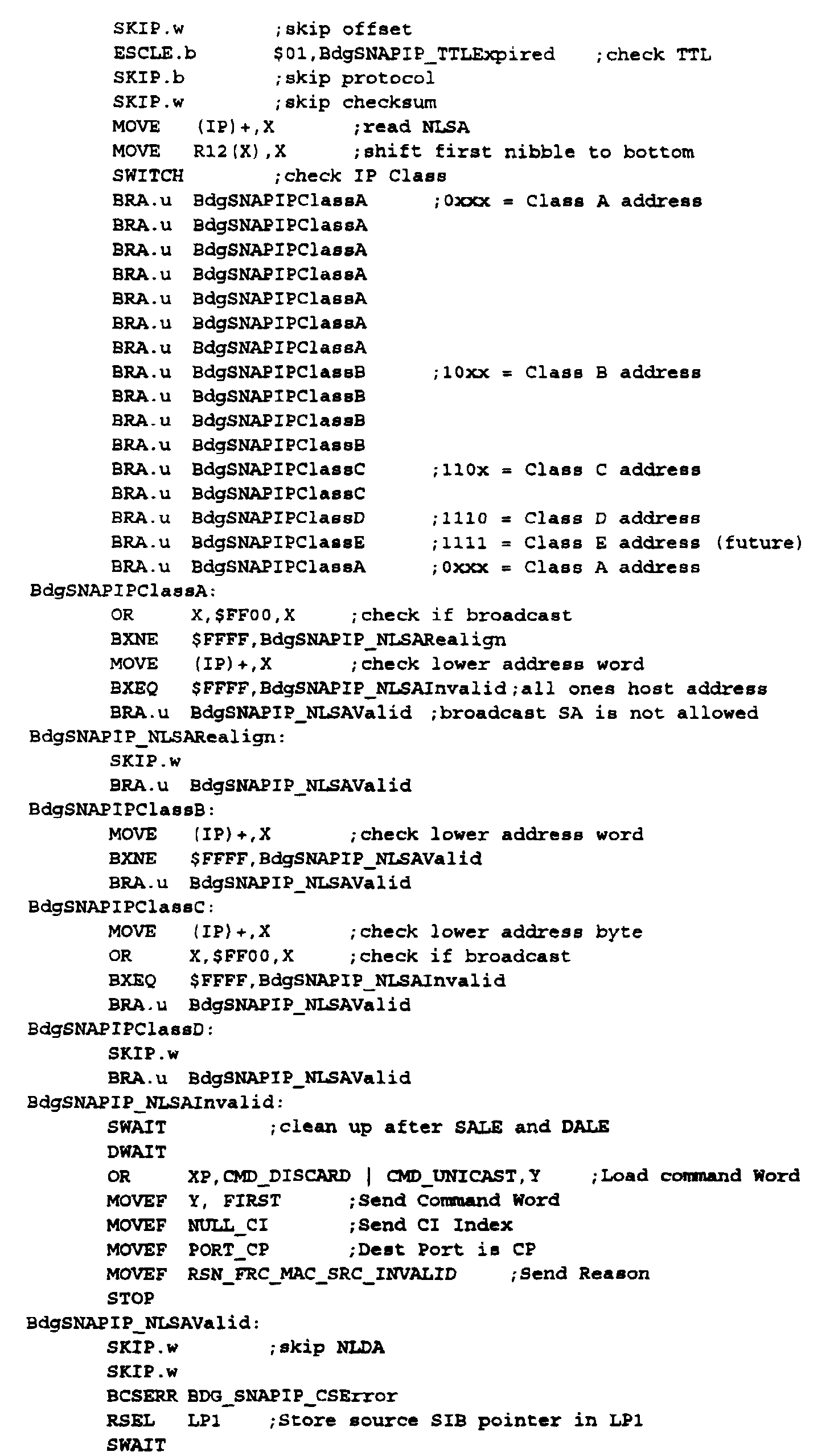
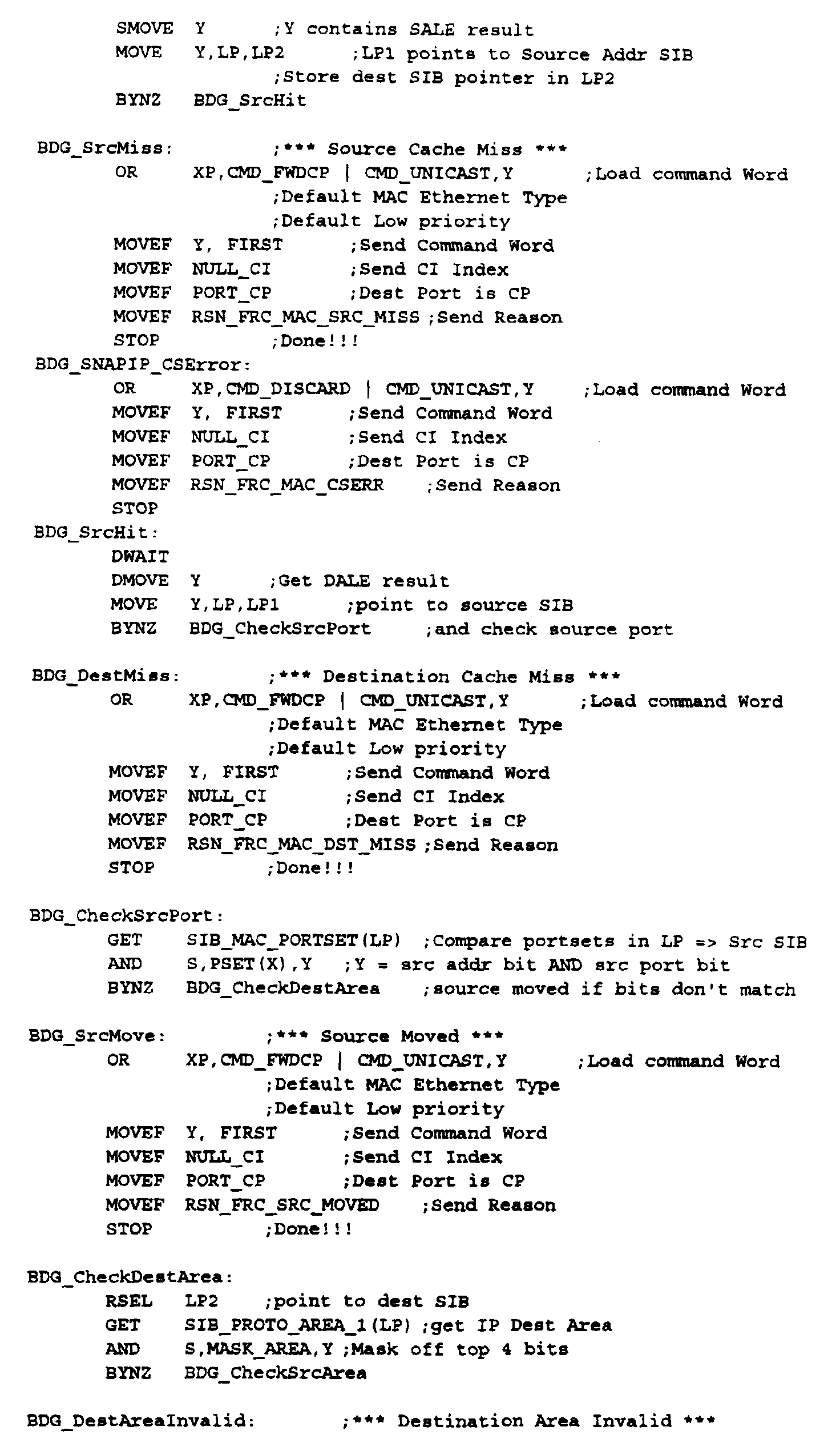

- The described look-up engine is capable of performing bridge-router and most network layer look-ups in less than 5.6 µs (1/178,000) with to minimum RAM requirements and cost and maximizes flexibility for future additions/corrections without hardware changes.
- The intended application of the look-up engine is high performance LAN systems and other packet-based devices.
-
- BRIDGE-ROUTER
- A LAN bridging-routing device, with 12 ethernet ports and 1 ATM port.
- ATM
- Asynchronous Transfer Mode. A cell relay standard.
- ABS
- Address/Broadcast Server A component of a Route Server that handles address resolution and broadcast traffic.
- AXE
- A Transfer Engine
- DA
- Destination Address. The MAC address of the intended destination of a MAC frame.
- DALE
- Destination Address Look-up Engine. The LUE component that generally searches through a table of MAC layer destination addresses.
- CI
- Connection Identifier. A number internally used to indicate a particular connection.
- IP
- Internet Protocol A popular network layer protocol used by the Internet community.
- IPX
- Internet Packet Exchange A Novell developed network layer protocol.
- LEC
- Look-up Engine Controller. The LUE component that executes microcode.
- LUE
- Look-up Engine.
- MAC
- Medium Access Control. A term commonly encountered in IEEE 802 standards generally referring to how a particular medium (ie. Ethernet) is used. "MAC address" is commonly used to refer to the globally unique 48 bit address given to all interface cards adhering somewhat to the IEEE 802 standards.
- RS
- Route Server.
- SA
- Source Address. The MAC address of the originator of a MAC frame.
- SALE
- Source Address Look-up Engine. The LUE component that generally searches through a table of MAC layer source addresses.
- SIB
- Station Information Block. The data structure in the LUE that holds relevant information about an endstation.
- CAM
- Content Addressable Memory.
- VPI
- Virtual Path Identifier
- VCI
- Virtual Channel Identifier
- Control Processor
- The processor in the Bridge-router that handles management functions
Claims (21)
- An arrangement for parsing packets in a packet-based data transmission network, said packets including packet headers divided into fields having values representing information pertaining to the packet, said arrangement comprising an input for receiving fields from said packet headers of incoming packets, a memory for storing information related to possible values of said fields, and a look-up engine for retrieving said stored information appropriate to a received field value, characterized in that said look-up engine (1) includes at least one said memory (6, 8) containing said stored information organized in a hierarchical tree structure, and a microcode controller (3) for controlling the operation of said look-up engine (1, 2) while performing bit pattern recognition on at least a portion of the packet.
- An arrangement as claimed in claim 1, characterized in that said at least one memory stores (6,8) address information and is associated with at least one address controller (5, 7) controlled by said microcode controller (3).
- An arrangement as claimed in claim 2, characterized in said at least one address controller (5, 7) searches addresses in said at least one memory using nibble indexing on said fields.
- An arrangement as claimed in claim 3, characterized in that said at least one address controller (5, 7) concatenates a first nibble of an incoming field value with a root pointer to obtain an index to a root pointer array, retrieves a word at a location identified by said index, concatenates the next nibble with the next word to form the next painter and so on until said related information is retrieved.
- An arrangement as claimed in any one of claims 1 to 4, characterized in that said at least one memory is a random access memory (RAM).
- An arrangement as claimed in any one of claims 1 to 5, characterized said fields comprise variable portions of the packet and said at least one portion is a fixed portion of the packet.
- An arrangement as claimed in any one of claims 2 to 6, characterized in that it comprises two said memories (6,8) with associated controllers (5,7) operating in parallel, one of said memories (8) storing source address information and the other of said memories (6) storing destination address information.
- An arrangement as claimed in claim 6, characterized in that said related information for the destination address comprises the path data associated with said respective destination.
- An arrangement as claimed in any one of claims 1 to 8, characterized in that said microcode controller (3) comprises an interface memory (21) for receiving said incoming packets, a station information block memory (20) for storing information pertaining to endstations, and a microcode memory (4) storing microcode instructions.
- An arrangement as claimed in claim 9, characterized in that the microcode controller (3) parses the remainder of the packet header using a specific instruction set while said information is retrieved from said memories.
- An arrangement as claimed in claim 10, characterized in that said microcode controller comprises separate buses for instructions and data.
- An arrangement as claimed in claim 11, characterized in that said microcode controller (3) further comprises means for implementing optimized instructions that perform bit level logical comparisons and conditional branches within the same cycle and other instructions tailored to retrieving data from nibble-indexed data structures.
- An arrangement as claimed in claim 12, characterized in that said microcode controller is implemented as an ASIC processor.
- A method of parsing packets in a packet-based data transmission network, said packets including packet headers divided into fields having values representing information pertaining to the packet, comprising storing information related to possible values of said fields, receiving fields from said packet headers of incoming packets, and retrieving by means of a look-up engine said stored information appropriate to a received field value, characterized in that said information is retrieved from a memory organized in a hierarchical tree structure under the control of a microcode controller while said microcode controller performs bit pattern recognition on at least a portion of the packet.
- A method as claimed in claim 14, characterized in that at each decision point on the tree structure, in retrieving said information a current field is compared with a known value or range, a current field pointer is moved and branched to new code if said comparison results in a first logical condition, and if said comparison results in a second logical condition, the current field is compared to a different value or range, and so on until a said comparison results in said first logical condition.
- A method as claimed in claim 14 or 15, characterized in that said at least one memory organized in a tree structure is searched using nibble indexing.
- A method as claimed in claim 16, characterized in that a first nibble of an incoming field value is concatenated with a root pointer to obtain an index to a root pointer array, a word at a location identified by said index is retrieved, the next nibble is concatenated with the next word to form the next pointer and so on until said related information is retrieved.
- A method as claimed in any one of claims 14 to 17, characterized in that said at least one portion is a fixed portion.
- A method as claimed in any one of claims 14 to 17, characterized in that said fields constitute variable portions of the packet.
- A method as claimed in claim 22, characterized in that said fields comprise address fields.
- A method as claimed in claim 20, characterized in that one of said fields comprises a destination address and said related information comprises the path data associated with said respective destination address, and another of said fields comprises a source address.
Applications Claiming Priority (3)
| Application Number | Priority Date | Filing Date | Title |
|---|---|---|---|
| GB9326476 | 1993-12-24 | ||
| GB939326476A GB9326476D0 (en) | 1993-12-24 | 1993-12-24 | Network |
| PCT/CA1994/000695 WO1995018497A1 (en) | 1993-12-24 | 1994-12-21 | Look-up engine for packet-based network |
Publications (2)
| Publication Number | Publication Date |
|---|---|
| EP0736236A1 EP0736236A1 (en) | 1996-10-09 |
| EP0736236B1 true EP0736236B1 (en) | 2000-08-30 |
Family
ID=10747243
Family Applications (1)
| Application Number | Title | Priority Date | Filing Date |
|---|---|---|---|
| EP95903734A Expired - Lifetime EP0736236B1 (en) | 1993-12-24 | 1994-12-21 | Look-up engine for packet-based network |
Country Status (8)
| Country | Link |
|---|---|
| US (1) | US5917821A (en) |
| EP (1) | EP0736236B1 (en) |
| JP (1) | JPH09511105A (en) |
| AU (1) | AU703464B2 (en) |
| CA (1) | CA2179613A1 (en) |
| DE (1) | DE69425757T2 (en) |
| GB (1) | GB9326476D0 (en) |
| WO (1) | WO1995018497A1 (en) |
Families Citing this family (154)
| Publication number | Priority date | Publication date | Assignee | Title |
|---|---|---|---|---|
| US6308148B1 (en) | 1996-05-28 | 2001-10-23 | Cisco Technology, Inc. | Network flow data export |
| DE19629765A1 (en) * | 1996-07-23 | 1998-01-29 | Siemens Ag | Address reduction method in ATM switching systems |
| US6163392A (en) | 1997-05-23 | 2000-12-19 | Ciena Corporation | Distributed intelligence wavelength division multiplexed network |
| US6185207B1 (en) * | 1997-06-19 | 2001-02-06 | International Business Machines Corporation | Communication system having a local area network adapter for selectively deleting information and method therefor |
| US6172980B1 (en) * | 1997-09-11 | 2001-01-09 | 3Com Corporation | Multiple protocol support |
| US6301256B1 (en) | 1997-09-17 | 2001-10-09 | Sony Corporation | Selection technique for preventing a source port from becoming a destination port in a multi-port bridge for a local area network |
| US6442168B1 (en) | 1997-09-17 | 2002-08-27 | Sony Corporation | High speed bus structure in a multi-port bridge for a local area network |
| US6446173B1 (en) | 1997-09-17 | 2002-09-03 | Sony Corporation | Memory controller in a multi-port bridge for a local area network |
| US6363067B1 (en) | 1997-09-17 | 2002-03-26 | Sony Corporation | Staged partitioned communication bus for a multi-port bridge for a local area network |
| US6744728B1 (en) | 1997-09-17 | 2004-06-01 | Sony Corporation & Sony Electronics, Inc. | Data pipeline timing optimization technique in a multi-port bridge for a local area network |
| US6617879B1 (en) | 1997-09-17 | 2003-09-09 | Sony Corporation | Transparently partitioned communication bus for multi-port bridge for a local area network |
| US6308218B1 (en) | 1997-09-17 | 2001-10-23 | Sony Corporation | Address look-up mechanism in a multi-port bridge for a local area network |
| US6175867B1 (en) * | 1998-03-23 | 2001-01-16 | Mci World Com, Inc. | System and method for managing networks addressed via common network addresses |
| US6256307B1 (en) * | 1998-03-27 | 2001-07-03 | Hewlett-Packard Co. | Local area network receive filter |
| US6700891B1 (en) * | 1998-06-25 | 2004-03-02 | Cisco Technology, Inc. | Apparatus and method for providing a device level security mechanism in a network |
| US6876653B2 (en) * | 1998-07-08 | 2005-04-05 | Broadcom Corporation | Fast flexible filter processor based architecture for a network device |
| US6308219B1 (en) * | 1998-07-31 | 2001-10-23 | Cisco Technology, Inc. | Routing table lookup implemented using M-trie having nodes duplicated in multiple memory banks |
| US7333484B2 (en) * | 1998-08-07 | 2008-02-19 | Intel Corporation | Services processor having a packet editing unit |
| US7133400B1 (en) * | 1998-08-07 | 2006-11-07 | Intel Corporation | System and method for filtering data |
| GB2340701B (en) * | 1998-08-15 | 2003-06-25 | Roke Manor Research | Programmable packet header processor |
| US6359886B1 (en) * | 1998-08-17 | 2002-03-19 | Compaq Computer Corporation | Method and apparatus for filtering and routing communications frames |
| JP3735471B2 (en) * | 1998-10-05 | 2006-01-18 | 株式会社日立製作所 | Packet relay device and LSI |
| JP3228249B2 (en) * | 1998-12-04 | 2001-11-12 | 日本電気株式会社 | Router device |
| US7899052B1 (en) * | 1999-01-27 | 2011-03-01 | Broadcom Corporation | Memory structure for resolving addresses in a packet-based network switch |
| KR20000054938A (en) * | 1999-02-01 | 2000-09-05 | 서평원 | Method and Apparatus for Packet Processing in Ethernet Switching System |
| US6192051B1 (en) * | 1999-02-26 | 2001-02-20 | Redstone Communications, Inc. | Network router search engine using compressed tree forwarding table |
| US6789116B1 (en) | 1999-06-30 | 2004-09-07 | Hi/Fn, Inc. | State processor for pattern matching in a network monitor device |
| US6771646B1 (en) | 1999-06-30 | 2004-08-03 | Hi/Fn, Inc. | Associative cache structure for lookups and updates of flow records in a network monitor |
| DE60045552D1 (en) | 1999-06-30 | 2011-03-03 | Apptitude Inc | METHOD AND DEVICE TO MONITOR THE NETWORK TRANSPORT |
| US6553029B1 (en) * | 1999-07-09 | 2003-04-22 | Pmc-Sierra, Inc. | Link aggregation in ethernet frame switches |
| US6427169B1 (en) * | 1999-07-30 | 2002-07-30 | Intel Corporation | Parsing a packet header |
| US7310688B1 (en) | 1999-08-30 | 2007-12-18 | Ciena Corporation | Relative addressing for network elements |
| JP3643507B2 (en) * | 1999-09-20 | 2005-04-27 | 株式会社東芝 | Packet processing apparatus and packet processing method |
| US6631419B1 (en) * | 1999-09-22 | 2003-10-07 | Juniper Networks, Inc. | Method and apparatus for high-speed longest prefix and masked prefix table search |
| US6625152B1 (en) * | 1999-10-13 | 2003-09-23 | Cisco Technology, Inc. | Methods and apparatus for transferring data using a filter index |
| US6779043B1 (en) * | 1999-11-16 | 2004-08-17 | National Semiconductor Corporation | Network address manager |
| US6711153B1 (en) * | 1999-12-13 | 2004-03-23 | Ascend Communications, Inc. | Route lookup engine |
| SE9904685D0 (en) * | 1999-12-17 | 1999-12-17 | Switchcore Ab | A programmable packaged decoder |
| US6697873B1 (en) * | 1999-12-20 | 2004-02-24 | Zarlink Semiconductor V.N., Inc. | High speed MAC address search engine |
| US6961337B2 (en) * | 2000-01-06 | 2005-11-01 | International Business Machines Corporation | Interleaved processing system for processing frames within a network router |
| US6988238B1 (en) | 2000-01-24 | 2006-01-17 | Ati Technologies, Inc. | Method and system for handling errors and a system for receiving packet stream data |
| US6807585B2 (en) * | 2001-02-22 | 2004-10-19 | Ati Technologies, Inc. | Method and system for parsing section data |
| US7366961B1 (en) | 2000-01-24 | 2008-04-29 | Ati Technologies, Inc. | Method and system for handling errors |
| US6810031B1 (en) | 2000-02-29 | 2004-10-26 | Celox Networks, Inc. | Method and device for distributing bandwidth |
| US7000034B2 (en) * | 2000-03-02 | 2006-02-14 | Agere Systems Inc. | Function interface system and method of processing issued functions between co-processors |
| US6988235B2 (en) * | 2000-03-02 | 2006-01-17 | Agere Systems Inc. | Checksum engine and a method of operation thereof |
| US6850516B2 (en) * | 2000-03-02 | 2005-02-01 | Agere Systems Inc. | Virtual reassembly system and method of operation thereof |
| US7200684B1 (en) * | 2000-04-13 | 2007-04-03 | International Business Machines Corporation | Network data packet classification and demultiplexing |
| US6798777B1 (en) | 2000-04-17 | 2004-09-28 | Juniper Networks, Inc. | Filtering and route lookup in a switching device |
| US7688727B1 (en) | 2000-04-17 | 2010-03-30 | Juniper Networks, Inc. | Filtering and route lookup in a switching device |
| US7215637B1 (en) | 2000-04-17 | 2007-05-08 | Juniper Networks, Inc. | Systems and methods for processing packets |
| US6574195B2 (en) * | 2000-04-19 | 2003-06-03 | Caspian Networks, Inc. | Micro-flow management |
| US7075926B2 (en) * | 2000-05-24 | 2006-07-11 | Alcatel Internetworking, Inc. (Pe) | Programmable packet processor with flow resolution logic |
| US7111071B1 (en) * | 2000-06-29 | 2006-09-19 | Intel Corporation | Longest prefix match for IP routers |
| US6711661B1 (en) | 2000-06-29 | 2004-03-23 | Motorola, Inc. | Method and apparatus for performing hierarchical address translation |
| US7373425B2 (en) * | 2000-08-22 | 2008-05-13 | Conexant Systems, Inc. | High-speed MAC address search engine |
| US6854117B1 (en) | 2000-10-31 | 2005-02-08 | Caspian Networks, Inc. | Parallel network processor array |
| JP4151217B2 (en) * | 2000-12-15 | 2008-09-17 | 沖電気工業株式会社 | Datagram transfer device |
| US7069422B2 (en) * | 2000-12-22 | 2006-06-27 | Modelski Richard P | Load-shift carry instruction |
| WO2002063430A2 (en) * | 2001-02-06 | 2002-08-15 | Atlantic Technology Ventures, Inc. | Superconducting packet switch |
| US7139242B2 (en) * | 2001-03-28 | 2006-11-21 | Proficient Networks, Inc. | Methods, apparatuses and systems facilitating deployment, support and configuration of network routing policies |
| US20020141378A1 (en) * | 2001-03-28 | 2002-10-03 | Bays Robert James | Methods, apparatuses and systems facilitating deployment, support and configuration of network routing policies |
| US7292586B2 (en) * | 2001-03-30 | 2007-11-06 | Nokia Inc. | Micro-programmable protocol packet parser and encapsulator |
| US6751627B2 (en) * | 2001-07-23 | 2004-06-15 | Networks Associates Technology, Inc. | Method and apparatus to facilitate accessing data in network management protocol tables |
| DE10147419A1 (en) * | 2001-09-26 | 2003-04-24 | Siemens Ag | Method for creating a dynamic address table for a coupling node in a data network and method for transmitting a data telegram |
| US7065083B1 (en) * | 2001-10-04 | 2006-06-20 | Cisco Technology, Inc. | Method and apparatus for dynamically generating lookup words for content-addressable memories |
| US7389360B1 (en) | 2001-11-05 | 2008-06-17 | Juniper Networks, Inc. | Context switched route lookup key engine |
| US6968393B1 (en) * | 2001-11-19 | 2005-11-22 | Redback Networks, Inc. | Method and apparatus for an attribute oriented routing update |
| US7421515B2 (en) * | 2002-01-17 | 2008-09-02 | Hewlett-Packard Development Company, L.P. | Method and system for communications network |
| US7737134B2 (en) * | 2002-03-13 | 2010-06-15 | The Texas A & M University System | Anticancer agents and use |
| US6972978B1 (en) | 2002-03-15 | 2005-12-06 | Integrated Device Technology, Inc. | Content addressable memory (CAM) devices with block select and pipelined virtual sector look-up control and methods of operating same |
| US6867991B1 (en) | 2003-07-03 | 2005-03-15 | Integrated Device Technology, Inc. | Content addressable memory devices with virtual partitioning and methods of operating the same |
| US20030185220A1 (en) * | 2002-03-27 | 2003-10-02 | Moshe Valenci | Dynamically loading parsing capabilities |
| US7688823B2 (en) * | 2002-06-04 | 2010-03-30 | Alcatel-Lucent Usa Inc. | Efficient mechanism for wire-tapping network traffic |
| US7508825B2 (en) * | 2002-08-05 | 2009-03-24 | Intel Corporation | Data packet classification |
| US7689485B2 (en) * | 2002-08-10 | 2010-03-30 | Cisco Technology, Inc. | Generating accounting data based on access control list entries |
| US7894480B1 (en) * | 2002-08-27 | 2011-02-22 | Hewlett-Packard Company | Computer system and network interface with hardware based rule checking for embedded firewall |
| US7724740B1 (en) * | 2002-08-27 | 2010-05-25 | 3Com Corporation | Computer system and network interface supporting class of service queues |
| CN100574312C (en) * | 2002-09-06 | 2009-12-23 | 因芬奈昂技术股份有限公司 | Analyzers that analyze packets of data |
| US7093099B2 (en) * | 2002-12-12 | 2006-08-15 | Alacritech, Inc. | Native lookup instruction for file-access processor searching a three-level lookup cache for variable-length keys |
| US7254696B2 (en) * | 2002-12-12 | 2007-08-07 | Alacritech, Inc. | Functional-level instruction-set computer architecture for processing application-layer content-service requests such as file-access requests |
| JP4108524B2 (en) * | 2003-04-14 | 2008-06-25 | 日本電気株式会社 | ATM bridge device and loop detection method in ATM bridge |
| US7716742B1 (en) * | 2003-05-12 | 2010-05-11 | Sourcefire, Inc. | Systems and methods for determining characteristics of a network and analyzing vulnerabilities |
| US7082493B1 (en) | 2003-10-31 | 2006-07-25 | Integrated Device Technology, Inc. | CAM-based search engines and packet coprocessors having results status signaling for completed contexts |
| US7539681B2 (en) * | 2004-07-26 | 2009-05-26 | Sourcefire, Inc. | Methods and systems for multi-pattern searching |
| US7496962B2 (en) * | 2004-07-29 | 2009-02-24 | Sourcefire, Inc. | Intrusion detection strategies for hypertext transport protocol |
| US7460544B2 (en) * | 2004-12-29 | 2008-12-02 | Intel Corporation | Flexible mesh structure for hierarchical scheduling |
| US7548563B1 (en) * | 2005-04-01 | 2009-06-16 | Marvell International Ltd. | Data transmission using address encoding |
| US7325074B2 (en) * | 2005-09-28 | 2008-01-29 | Cisco Technology, Inc. | Incremental compilation of packet classifications using fragmented tables |
| US7733803B2 (en) * | 2005-11-14 | 2010-06-08 | Sourcefire, Inc. | Systems and methods for modifying network map attributes |
| US8046833B2 (en) * | 2005-11-14 | 2011-10-25 | Sourcefire, Inc. | Intrusion event correlation with network discovery information |
| US8547843B2 (en) * | 2006-01-20 | 2013-10-01 | Saisei Networks Pte Ltd | System, method, and computer program product for controlling output port utilization |
| US20070171825A1 (en) * | 2006-01-20 | 2007-07-26 | Anagran, Inc. | System, method, and computer program product for IP flow routing |
| US7726309B2 (en) * | 2006-06-05 | 2010-06-01 | Ric Investments, Llc | Flexible connector |
| DE602006014667D1 (en) * | 2006-06-23 | 2010-07-15 | Nippon Office Automation Co Lt | Protocol and session analyzer |
| US8194643B2 (en) | 2006-10-19 | 2012-06-05 | Embarq Holdings Company, Llc | System and method for monitoring the connection of an end-user to a remote network |
| US8717911B2 (en) | 2006-06-30 | 2014-05-06 | Centurylink Intellectual Property Llc | System and method for collecting network performance information |
| US8488447B2 (en) | 2006-06-30 | 2013-07-16 | Centurylink Intellectual Property Llc | System and method for adjusting code speed in a transmission path during call set-up due to reduced transmission performance |
| US8289965B2 (en) | 2006-10-19 | 2012-10-16 | Embarq Holdings Company, Llc | System and method for establishing a communications session with an end-user based on the state of a network connection |
| US8184549B2 (en) | 2006-06-30 | 2012-05-22 | Embarq Holdings Company, LLP | System and method for selecting network egress |
| US9094257B2 (en) | 2006-06-30 | 2015-07-28 | Centurylink Intellectual Property Llc | System and method for selecting a content delivery network |
| US7948909B2 (en) | 2006-06-30 | 2011-05-24 | Embarq Holdings Company, Llc | System and method for resetting counters counting network performance information at network communications devices on a packet network |
| US8000318B2 (en) | 2006-06-30 | 2011-08-16 | Embarq Holdings Company, Llc | System and method for call routing based on transmission performance of a packet network |
| US7948988B2 (en) * | 2006-07-27 | 2011-05-24 | Sourcefire, Inc. | Device, system and method for analysis of fragments in a fragment train |
| US7701945B2 (en) | 2006-08-10 | 2010-04-20 | Sourcefire, Inc. | Device, system and method for analysis of segments in a transmission control protocol (TCP) session |
| US8750158B2 (en) | 2006-08-22 | 2014-06-10 | Centurylink Intellectual Property Llc | System and method for differentiated billing |
| US7940735B2 (en) | 2006-08-22 | 2011-05-10 | Embarq Holdings Company, Llc | System and method for selecting an access point |
| US8107366B2 (en) | 2006-08-22 | 2012-01-31 | Embarq Holdings Company, LP | System and method for using centralized network performance tables to manage network communications |
| US8144586B2 (en) | 2006-08-22 | 2012-03-27 | Embarq Holdings Company, Llc | System and method for controlling network bandwidth with a connection admission control engine |
| US7684332B2 (en) | 2006-08-22 | 2010-03-23 | Embarq Holdings Company, Llc | System and method for adjusting the window size of a TCP packet through network elements |
| US8130793B2 (en) | 2006-08-22 | 2012-03-06 | Embarq Holdings Company, Llc | System and method for enabling reciprocal billing for different types of communications over a packet network |
| US8743703B2 (en) | 2006-08-22 | 2014-06-03 | Centurylink Intellectual Property Llc | System and method for tracking application resource usage |
| US8537695B2 (en) | 2006-08-22 | 2013-09-17 | Centurylink Intellectual Property Llc | System and method for establishing a call being received by a trunk on a packet network |
| US8223655B2 (en) | 2006-08-22 | 2012-07-17 | Embarq Holdings Company, Llc | System and method for provisioning resources of a packet network based on collected network performance information |
| US8549405B2 (en) | 2006-08-22 | 2013-10-01 | Centurylink Intellectual Property Llc | System and method for displaying a graphical representation of a network to identify nodes and node segments on the network that are not operating normally |
| US8307065B2 (en) | 2006-08-22 | 2012-11-06 | Centurylink Intellectual Property Llc | System and method for remotely controlling network operators |
| US8040811B2 (en) | 2006-08-22 | 2011-10-18 | Embarq Holdings Company, Llc | System and method for collecting and managing network performance information |
| US8015294B2 (en) | 2006-08-22 | 2011-09-06 | Embarq Holdings Company, LP | Pin-hole firewall for communicating data packets on a packet network |
| US8102770B2 (en) | 2006-08-22 | 2012-01-24 | Embarq Holdings Company, LP | System and method for monitoring and optimizing network performance with vector performance tables and engines |
| US8619600B2 (en) | 2006-08-22 | 2013-12-31 | Centurylink Intellectual Property Llc | System and method for establishing calls over a call path having best path metrics |
| US8199653B2 (en) | 2006-08-22 | 2012-06-12 | Embarq Holdings Company, Llc | System and method for communicating network performance information over a packet network |
| US8238253B2 (en) | 2006-08-22 | 2012-08-07 | Embarq Holdings Company, Llc | System and method for monitoring interlayer devices and optimizing network performance |
| US8576722B2 (en) | 2006-08-22 | 2013-11-05 | Centurylink Intellectual Property Llc | System and method for modifying connectivity fault management packets |
| US9479341B2 (en) | 2006-08-22 | 2016-10-25 | Centurylink Intellectual Property Llc | System and method for initiating diagnostics on a packet network node |
| US8407765B2 (en) | 2006-08-22 | 2013-03-26 | Centurylink Intellectual Property Llc | System and method for restricting access to network performance information tables |
| US8125897B2 (en) | 2006-08-22 | 2012-02-28 | Embarq Holdings Company Lp | System and method for monitoring and optimizing network performance with user datagram protocol network performance information packets |
| US7843831B2 (en) | 2006-08-22 | 2010-11-30 | Embarq Holdings Company Llc | System and method for routing data on a packet network |
| US8274905B2 (en) | 2006-08-22 | 2012-09-25 | Embarq Holdings Company, Llc | System and method for displaying a graph representative of network performance over a time period |
| US8144587B2 (en) | 2006-08-22 | 2012-03-27 | Embarq Holdings Company, Llc | System and method for load balancing network resources using a connection admission control engine |
| US8189468B2 (en) | 2006-10-25 | 2012-05-29 | Embarq Holdings, Company, LLC | System and method for regulating messages between networks |
| US8531954B2 (en) | 2006-08-22 | 2013-09-10 | Centurylink Intellectual Property Llc | System and method for handling reservation requests with a connection admission control engine |
| US8098579B2 (en) | 2006-08-22 | 2012-01-17 | Embarq Holdings Company, LP | System and method for adjusting the window size of a TCP packet through remote network elements |
| US8224255B2 (en) | 2006-08-22 | 2012-07-17 | Embarq Holdings Company, Llc | System and method for managing radio frequency windows |
| US8064391B2 (en) | 2006-08-22 | 2011-11-22 | Embarq Holdings Company, Llc | System and method for monitoring and optimizing network performance to a wireless device |
| US8228791B2 (en) | 2006-08-22 | 2012-07-24 | Embarq Holdings Company, Llc | System and method for routing communications between packet networks based on intercarrier agreements |
| US8194555B2 (en) | 2006-08-22 | 2012-06-05 | Embarq Holdings Company, Llc | System and method for using distributed network performance information tables to manage network communications |
| EP2076866A2 (en) * | 2006-10-06 | 2009-07-08 | Sourcefire, Inc. | Device, system and method for use of micro-policies in intrusion detection/prevention |
| US8069352B2 (en) | 2007-02-28 | 2011-11-29 | Sourcefire, Inc. | Device, system and method for timestamp analysis of segments in a transmission control protocol (TCP) session |
| US8806059B1 (en) * | 2007-04-05 | 2014-08-12 | Juniper Networks, Inc. | Rule tree for network device |
| EP2156290B1 (en) * | 2007-04-30 | 2020-03-25 | Cisco Technology, Inc. | Real-time awareness for a computer network |
| US7724684B2 (en) | 2007-05-24 | 2010-05-25 | Modelware, Inc. | System and method for designing and implementing packet processing products |
| US8111692B2 (en) | 2007-05-31 | 2012-02-07 | Embarq Holdings Company Llc | System and method for modifying network traffic |
| US8683572B1 (en) | 2008-01-24 | 2014-03-25 | Dunti Llc | Method and apparatus for providing continuous user verification in a packet-based network |
| US8068425B2 (en) | 2008-04-09 | 2011-11-29 | Embarq Holdings Company, Llc | System and method for using network performance information to determine improved measures of path states |
| US8474043B2 (en) * | 2008-04-17 | 2013-06-25 | Sourcefire, Inc. | Speed and memory optimization of intrusion detection system (IDS) and intrusion prevention system (IPS) rule processing |
| US8356125B1 (en) * | 2008-05-15 | 2013-01-15 | Xilinx, Inc. | Method and apparatus for providing a channelized buffer |
| WO2010045089A1 (en) | 2008-10-08 | 2010-04-22 | Sourcefire, Inc. | Target-based smb and dce/rpc processing for an intrusion detection system or intrusion prevention system |
| WO2011130510A1 (en) | 2010-04-16 | 2011-10-20 | Sourcefire, Inc. | System and method for near-real time network attack detection, and system and method for unified detection via detection routing |
| US8433790B2 (en) | 2010-06-11 | 2013-04-30 | Sourcefire, Inc. | System and method for assigning network blocks to sensors |
| US8671182B2 (en) | 2010-06-22 | 2014-03-11 | Sourcefire, Inc. | System and method for resolving operating system or service identity conflicts |
| KR101747079B1 (en) | 2011-02-17 | 2017-06-14 | 세이블 네트웍스 인코포레이티드 | Methods and systems for detecting and mitigating a high-rate distributed denial of service (ddos) attack |
| US8601034B2 (en) | 2011-03-11 | 2013-12-03 | Sourcefire, Inc. | System and method for real time data awareness |
| US8902890B2 (en) | 2011-05-27 | 2014-12-02 | International Business Machines Corporation | Memory saving packet modification |
| EP2850793B1 (en) | 2012-05-14 | 2016-09-21 | Sable Networks, Inc | System and method for ensuring subscriber fairness using outlier detection |
Family Cites Families (3)
| Publication number | Priority date | Publication date | Assignee | Title |
|---|---|---|---|---|
| US5095480A (en) * | 1989-06-16 | 1992-03-10 | Fenner Peter R | Message routing system for shared communication media networks |
| US5088090A (en) * | 1990-01-31 | 1992-02-11 | Rad Network Devices Ltd. | Routing system to interconnect local area networks |
| AU4661793A (en) * | 1992-07-02 | 1994-01-31 | Wellfleet Communications | Data packet processing method and apparatus |
-
1993
- 1993-12-24 GB GB939326476A patent/GB9326476D0/en active Pending
-
1994
- 1994-12-21 EP EP95903734A patent/EP0736236B1/en not_active Expired - Lifetime
- 1994-12-21 WO PCT/CA1994/000695 patent/WO1995018497A1/en not_active Ceased
- 1994-12-21 AU AU12700/95A patent/AU703464B2/en not_active Ceased
- 1994-12-21 CA CA002179613A patent/CA2179613A1/en not_active Abandoned
- 1994-12-21 JP JP7517695A patent/JPH09511105A/en active Pending
- 1994-12-21 US US08/663,263 patent/US5917821A/en not_active Expired - Lifetime
- 1994-12-21 DE DE69425757T patent/DE69425757T2/en not_active Expired - Lifetime
Also Published As
| Publication number | Publication date |
|---|---|
| DE69425757T2 (en) | 2001-04-19 |
| GB9326476D0 (en) | 1994-02-23 |
| AU1270095A (en) | 1995-07-17 |
| CA2179613A1 (en) | 1995-07-06 |
| EP0736236A1 (en) | 1996-10-09 |
| JPH09511105A (en) | 1997-11-04 |
| US5917821A (en) | 1999-06-29 |
| AU703464B2 (en) | 1999-03-25 |
| WO1995018497A1 (en) | 1995-07-06 |
| DE69425757D1 (en) | 2000-10-05 |
Similar Documents
| Publication | Publication Date | Title |
|---|---|---|
| US5917821A (en) | Look-up engine for packet-based network | |
| US7167474B2 (en) | Network relaying apparatus and network relaying method capable of high-speed routing and packet transfer | |
| AU738983B2 (en) | Networking systems | |
| US5487064A (en) | Network layer packet structure | |
| US5604867A (en) | System for transmitting data between bus and network having device comprising first counter for providing transmitting rate and second counter for limiting frames exceeding rate | |
| US6032190A (en) | System and method for processing data packets | |
| US6683885B1 (en) | Network relaying apparatus and network relaying method | |
| JP3734704B2 (en) | Packet classification engine | |
| EP1005746B1 (en) | Method and device for network packet forwarding lookup with a reduced number of memory accesses | |
| EP1224773B1 (en) | Apparatus and method for identifying data packet types in real time on a network switch port | |
| Taylor et al. | Scalable IP lookup for programmable routers | |
| CA2326928C (en) | Route lookup engine | |
| JP2003508954A (en) | Network switch, components and operation method | |
| JP2003508967A (en) | Network switch using network processor and method | |
| JP2003508957A (en) | Network processor processing complex and method | |
| JP2003508851A (en) | Network processor, memory configuration and method | |
| JP2003508951A (en) | VLSI network processor and method | |
| KR20000023290A (en) | Flexible telecommunications switching network | |
| WO1996034479A1 (en) | Packet switching engine | |
| US6658003B1 (en) | Network relaying apparatus and network relaying method capable of high-speed flow detection | |
| EP1068710A2 (en) | System and process for high-speed pattern matching for application-level switching of data packets | |
| US7830892B2 (en) | VLAN translation in a network device | |
| US6711165B1 (en) | Apparatus and method for storing min terms in network switch port memory for access and compactness | |
| US6693906B1 (en) | Apparatus and method for buffer-free evaluation of packet data bytes with multiple min terms | |
| US6671277B1 (en) | Network relaying apparatus and network relaying method capable of high quality transfer of packets under stable service quality control |
Legal Events
| Date | Code | Title | Description |
|---|---|---|---|
| PUAI | Public reference made under article 153(3) epc to a published international application that has entered the european phase |
Free format text: ORIGINAL CODE: 0009012 |
|
| 17P | Request for examination filed |
Effective date: 19960706 |
|
| AK | Designated contracting states |
Kind code of ref document: A1 Designated state(s): BE DE FR GB IT SE |
|
| 17Q | First examination report despatched |
Effective date: 19971118 |
|
| GRAG | Despatch of communication of intention to grant |
Free format text: ORIGINAL CODE: EPIDOS AGRA |
|
| GRAG | Despatch of communication of intention to grant |
Free format text: ORIGINAL CODE: EPIDOS AGRA |
|
| GRAH | Despatch of communication of intention to grant a patent |
Free format text: ORIGINAL CODE: EPIDOS IGRA |
|
| GRAH | Despatch of communication of intention to grant a patent |
Free format text: ORIGINAL CODE: EPIDOS IGRA |
|
| GRAA | (expected) grant |
Free format text: ORIGINAL CODE: 0009210 |
|
| AK | Designated contracting states |
Kind code of ref document: B1 Designated state(s): BE DE FR GB IT SE |
|
| PG25 | Lapsed in a contracting state [announced via postgrant information from national office to epo] |
Ref country code: IT Free format text: LAPSE BECAUSE OF FAILURE TO SUBMIT A TRANSLATION OF THE DESCRIPTION OR TO PAY THE FEE WITHIN THE PRE;WARNING: LAPSES OF ITALIAN PATENTS WITH EFFECTIVE DATE BEFORE 2007 MAY HAVE OCCURRED AT ANY TIME BEFORE 2007. THE CORRECT EFFECTIVE DATE MAY BE DIFFERENT FROM THE ONE RECORDED.SCRIBED TIME-LIMIT Effective date: 20000830 Ref country code: BE Free format text: LAPSE BECAUSE OF FAILURE TO SUBMIT A TRANSLATION OF THE DESCRIPTION OR TO PAY THE FEE WITHIN THE PRESCRIBED TIME-LIMIT Effective date: 20000830 |
|
| REF | Corresponds to: |
Ref document number: 69425757 Country of ref document: DE Date of ref document: 20001005 |
|
| PG25 | Lapsed in a contracting state [announced via postgrant information from national office to epo] |
Ref country code: SE Free format text: LAPSE BECAUSE OF FAILURE TO SUBMIT A TRANSLATION OF THE DESCRIPTION OR TO PAY THE FEE WITHIN THE PRESCRIBED TIME-LIMIT Effective date: 20001130 |
|
| ET | Fr: translation filed | ||
| REG | Reference to a national code |
Ref country code: FR Ref legal event code: CD |
|
| PLBE | No opposition filed within time limit |
Free format text: ORIGINAL CODE: 0009261 |
|
| STAA | Information on the status of an ep patent application or granted ep patent |
Free format text: STATUS: NO OPPOSITION FILED WITHIN TIME LIMIT |
|
| REG | Reference to a national code |
Ref country code: FR Ref legal event code: CD |
|
| 26N | No opposition filed | ||
| REG | Reference to a national code |
Ref country code: GB Ref legal event code: IF02 |
|
| REG | Reference to a national code |
Ref country code: FR Ref legal event code: TP Owner name: ALCATEL LUCENT CANADA INC., CA Effective date: 20130725 Ref country code: FR Ref legal event code: CD Owner name: ALCATEL LUCENT CANADA INC., CA Effective date: 20130725 |
|
| REG | Reference to a national code |
Ref country code: FR Ref legal event code: GC Effective date: 20130820 |
|
| REG | Reference to a national code |
Ref country code: GB Ref legal event code: 732E Free format text: REGISTERED BETWEEN 20130829 AND 20130904 |
|
| PGFP | Annual fee paid to national office [announced via postgrant information from national office to epo] |
Ref country code: DE Payment date: 20131220 Year of fee payment: 20 Ref country code: GB Payment date: 20131219 Year of fee payment: 20 |
|
| PGFP | Annual fee paid to national office [announced via postgrant information from national office to epo] |
Ref country code: FR Payment date: 20131220 Year of fee payment: 20 |
|
| REG | Reference to a national code |
Ref country code: FR Ref legal event code: RG Effective date: 20141015 |
|
| REG | Reference to a national code |
Ref country code: DE Ref legal event code: R071 Ref document number: 69425757 Country of ref document: DE |
|
| REG | Reference to a national code |
Ref country code: DE Ref legal event code: R071 Ref document number: 69425757 Country of ref document: DE |
|
| REG | Reference to a national code |
Ref country code: GB Ref legal event code: PE20 Expiry date: 20141220 |
|
| PG25 | Lapsed in a contracting state [announced via postgrant information from national office to epo] |
Ref country code: GB Free format text: LAPSE BECAUSE OF EXPIRATION OF PROTECTION Effective date: 20141220 |