US6553029B1 - Link aggregation in ethernet frame switches - Google Patents
Link aggregation in ethernet frame switches Download PDFInfo
- Publication number
- US6553029B1 US6553029B1 US09/351,406 US35140699A US6553029B1 US 6553029 B1 US6553029 B1 US 6553029B1 US 35140699 A US35140699 A US 35140699A US 6553029 B1 US6553029 B1 US 6553029B1
- Authority
- US
- United States
- Prior art keywords
- address
- source
- ports
- physical
- destination
- Prior art date
- Legal status (The legal status is an assumption and is not a legal conclusion. Google has not performed a legal analysis and makes no representation as to the accuracy of the status listed.)
- Expired - Lifetime
Links
Images

Classifications
-
- H—ELECTRICITY
- H04—ELECTRIC COMMUNICATION TECHNIQUE
- H04L—TRANSMISSION OF DIGITAL INFORMATION, e.g. TELEGRAPHIC COMMUNICATION
- H04L49/00—Packet switching elements
- H04L49/35—Switches specially adapted for specific applications
- H04L49/351—Switches specially adapted for specific applications for local area network [LAN], e.g. Ethernet switches
-
- H—ELECTRICITY
- H04—ELECTRIC COMMUNICATION TECHNIQUE
- H04L—TRANSMISSION OF DIGITAL INFORMATION, e.g. TELEGRAPHIC COMMUNICATION
- H04L49/00—Packet switching elements
- H04L49/30—Peripheral units, e.g. input or output ports
- H04L49/3009—Header conversion, routing tables or routing tags
Definitions
- This invention is directed to the implementation of link aggregation (also known as trunking, or inverse multiplexing) in Ethernet frame switches.
- link aggregation also known as trunking, or inverse multiplexing
- a hardware and firmware combination distributes frames across parallel links without misordering problems.
- Link aggregation technology termed “inverse multiplexing” has been used for some time in wide-area networks, but has been adopted only recently (as “trunking”) in state-of-the-art Ethernet frame switches.
- Link aggregation provides redundancy and load balancing across medium access control (MAC) entities connecting Ethernet switches to each other, or to high-speed server computers.
- MAC medium access control
- the technique consists of establishing multiple, parallel physical links between two entities that must communicate with each other (i.e., switches, routers and/or network servers), and then logically binding these parallel links into a single logical link having a higher effective bandwidth than any one physical link.
- Packets belonging to a single packet stream, that must be transferred between the two communicating entities are separated and distributed across the physical links joining them using some well-defined algorithm by the source entity, and are subsequently recombined by the destination entity back into a single stream. Note that link aggregation does not encompass schemes for segmenting packets into smaller units and distributing them across multiple links; it is assumed that packets are transmitted in their entirety on specific physical links.
- a typical prior art Ethernet link aggregation implementation utilizes a hardware means for distributing packets across multiple physical links, and re-aggregating them at the receiving end. This is typically due to the high speeds involved (100 Mb/s or even 1000 Mb/s per link) in the packet transfer.
- the use of such hardware is expensive in terms of the silicon resources required to perform the distribution and collection functions, and is also inflexible in terms of the algorithms used to determine how packets may be distributed across links.
- the complexity of the distribution function when accounting for the various packet ordering and sequencing requirements of the Ethernet protocol renders a hardware-only approach difficult to design and debug.
- a well-partitioned, mixed hardware/firmware approach is preferable when implementing link aggregation at high speeds. This approach, permits high speeds to be attained while at the same time preserving flexibility in implementation, which is necessary for tracking changing standards or implementing different distribution algorithms.
- the preferred link aggregation scheme should satisfy the following objectives:
- connection is a particular combination of source and destination MAC addresses obtained from the Ethernet frame header.
- the link aggregation mechanism should distribute frames across multiple parallel physical links as evenly as possible, subject to the above ordering constraint.
- the distribution algorithm must be capable of preserving the frame ordering when a frame stream transitions from a flood—i.e., a multicast produced when the destination address within the frame is unknown—to a unicast after the destination address has been learned by the normal Ethernet bridging process.
- the distribution algorithm must preferably distribute not only unicast traffic but also multicast traffic (i.e., traffic sent to a set of destination physical ports) across aggregated links.
- the link aggregation scheme should use a minimum of hardware resources in order to lower cost, without sacrificing performance at the same time.
- This invention provides a link aggregation algorithm embodied within a mixed hardware/firmware packet forwarding datapath that accepts incoming frames, determines whether they are destined to be transferred across an aggregated link (i.e., a single logical link consisting of multiple physical links), and then distributes them across the multiple physical links using a pre-defined distribution algorithm.
- an aggregated link i.e., a single logical link consisting of multiple physical links
- the invention facilitates distribution of data packets between one or more physical incoming ports and one or more physical outgoing ports. Packets containing source and destination addresses are received on one or more of the incoming ports.
- An address look-up table stores previously processed source and destination addresses, together with source and destination contexts associated with the respective source and destination addresses. The contexts represent either a specific physical port, or an aggregated grouping of ports.
- a distribution table stores, for each aggregated grouping of outgoing ports, a corresponding aggregated group of identifiers of specific outgoing ports.
- each packet As each packet is received, its source and destination addresses are extracted and the address look-up table is searched for those source and destination addresses. If the address look-up table contains those source and destination addresses then the source and destination contexts associated with those source and destination addresses are retrieved from the address look-up table. If the address look-up table does not contain a source address corresponding to the extracted source address, then a source context corresponding to the extracted source address is derived and stored in the address look-up table with the extracted source address.
- the received packet is queued for outgoing transmission on that port. If the retrieved destination address context represents an aggregated grouping of outgoing ports, then the identifiers for the outgoing ports comprising that grouping are retrieved from the distribution table, and the received packet is queued for outgoing transmission on all of the outgoing ports comprising that grouping.
- the source context corresponding to an extracted source address is derived by producing a hash key through application of a hash function to the extracted source address.
- the incoming port on which the packet containing the extracted source address was received is identified. If the identified incoming port is within an aggregated grouping of incoming ports, then a port identifier representative that aggregated grouping is derived. If the identified incoming port is not within an aggregated grouping of incoming ports, then a port identifier representative of the identified incoming port is derived.
- the hash key and the port identifier are then combined to form the source context corresponding to the extracted source address.
- the hash function is preferably selected such that successive application of the hash function to all source and destination addresses expected to be seen by the Ethernet switch will produce a lowest value hash key, a highest value hash key, and a group of hash keys having intermediate values distributed evenly between the lowest and highest values.
- the distribution table contains a separate port identifier look-up table for each aggregated grouping of outgoing ports.
- the hash key is an N bit hash key; and, each port identifier look-up table contains 2 N entries occupying 2 N consecutive locations, with each entry being an identifier of a particular one of the physical outgoing ports.
- Identifiers for particular outgoing ports are retrieved from the distribution table by extracting first and second N bit hash keys which form part of the retrieved destination and source address contexts respectively.
- the hash keys are combined to form an N bit connection identifier.
- the port identifier look-up table corresponding to the aggregated grouping represented by the retrieved destination address is selected, and the entry at the table location corresponding to the value of the N bit connection identifier is retrieved.
- first and second hash keys are produced by applying a hash function to the extracted source and destination addresses respectively.
- the hash keys are combined to form an N bit connection identifier.
- the incoming port on which the packet containing the extracted source address was received is identified. All of the aggregated groupings are scanned to identify all outgoing ports to which packets may be directed from the incoming port on which the packet was received.
- the port identifier look-up table corresponding to the aggregated grouping containing that outgoing port is selected, the entry at the table location corresponding to the value of the N bit connection identifier is retrieved, and the received packet is queued for outgoing transmission on the outgoing port corresponding to the retrieved entry.
- FIG. 1 is a block diagram of a hardware and firmware link aggregation mechanism in accordance with the invention.
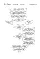
- FIG. 2 is flowchart which illustrates the general packet forwarding flow methodology of the invention.
- the hardware elements constituting the link aggregation packet datapath comprise address resolution unit 10 , MAC address look-up table 12 , embedded CPU 14 and queuing unit 18 .
- Address resolution unit 10 accepts Ethernet packets from multiple incoming packet streams, some of which may be logically grouped-to form aggregate links, and resolves the source and destination addresses in the-packets, as hereinafter explained.
- MAC address look-up table 12 which is typically implemented using random access memory (RAM), is used by address resolution unit 10 to translate Ethernet MAC addresses taken from packet headers into contexts which are used during the forwarding process, as hereinafter explained.
- Embedded CPU 14 accepts the contexts associated with the addresses contained within the incoming Ethernet packets, executes firmware routine 16 to update MAC address look-up table 12 with new information, and executes packet forwarding routine 20 by selecting one or more links on which to transfer individual packet streams.
- Queuing unit 18 accepts the incoming packet data and packet forwarding commands produced by embedded CPU 14 , and queues the packets on the selected link(s). The actual link aggregation collection and distribution processes are controlled via execution of packet forwarding firmware routine 20 by embedded CPU 14 , utilizing data in distribution table 22 .
- the general packet forwarding flow is shown in FIG. 2 and will now be described. It is assumed that external means exist for accepting and transmitting packets from and to the physical MAC links; such means are well known to and understood by persons skilled in the art, and need not be described here. The discussion will focus on the control operations required to transfer packets to and from these physical links, when some or all of these physical links are being aggregated into larger logical links.
- Address resolution unit 10 accepts multiple streams of packets (one stream from each physical link: FIG. 2, block 24 ) and performs an address look-up process on each packet using MAC address look-up table 12 (FIG. 2, block 26 ).
- Address lookup table 12 contains a set of MAC addresses known to the Ethernet switch as well as context information that must be associated with the MAC addresses for use in packet forwarding. (The contents of address look-up table 12 are generated by firmware running on embedded CPU 14 , as hereinafter explained.)
- Address resolution unit 10 thus extracts the source and destination MAC addresses from each Ethernet packet, looks up the addresses in MAC address look-up table 12 to determine if associated contexts exist for the source and destination MAC addresses, and also retrieves the contexts from table 12 if they exist. Address resolution unit 10 then presents the packet data along with the source and destination MAC address contexts (if found) to embedded CPU 14 for processing by packet forwarding firmware routine 20 (FIG. 2, block 28 ).
- Embedded CPU 14 implements packet forwarding firmware routine 20 to perform the actual control decisions required to forward the packet.
- Two different firmware routines 16 , 20 are executed.
- Address table creation (“learning function”) firmware routine 16 is invoked when address resolution unit 10 determines that a particular source MAC address found within a packet is not present in address look-up table 12 ; in which case table 12 is updated accordingly.
- Packet forwarding (“forwarding function”) firmware routine 20 is executed for every packet, to produce the actual forwarding command (i.e., the decision as to which physical port or ports the packet must be forwarded to) supplied to queuing unit 18 .
- Packet forwarding routine 20 utilizes distribution table 22 to select among ports that have been grouped into aggregates.
- the packet is passed to queuing unit 18 , along with the forwarding command generated by forwarding function 20 .
- Queuing unit 18 places the packet in one or more queues according to the forwarding command. Each queue corresponds to a specific physical port, with a one-to-one mapping between queues and ports.
- the packet is then stored within the queue(s) until it can be transmitted, after which it is read from the queue(s) and transmitted out the selected port(s). Note that the packet is transmitted out multiple ports if forwarding function 20 determines that the packet must be multicast to a set of destinations, rather than being unicast to a single specific destination.
- the learning function is responsible for creating and updating address look-up table 12 in response to incoming packets and in accordance with the basic requirements of standard Ethernet switches.
- address look-up table 12 need not be described.
- learning function 16 is invoked to update look-up table 12 with the new address (i.e. processing branches along the “No” exit from FIG. 2, block 36 ).
- Learning function 16 first computes a hash function on the source Ethernet MAC address, generating an N-bit hash key (“partial connection identifier”) from the 48-bit MAC address, where N is some small integer in the range of 3 to 8 (FIG. 2, block 38 ). The physical port on which the packet arrived is then determined.
- the logical identifier assigned to the aggregate group is also determined.
- the hash key is then stored into address look-up table 12 in conjunction with the actual Ethernet MAC address and the port identifier (FIG. 2, block 40 ).
- the physical port identifier is used if the port is not part of an aggregate group (i.e. if processing branched along the “No” exit from block 30 and through block 32 ), while the logical identifier is used for ports that have been aggregated (i.e. if processing branched along the “Yes” exit from block 30 and through block 34 ).
- the hash key and port identifier are considered to form the “context” for the given MAC address.
- the hash function should be selected to ensure an even distribution of hash key values over the range of MAC addresses that are expected to be seen by the Ethernet switch.
- the EXACTTM Ethernet switch system employs an exclusive-OR based hash function, wherein the 48-bit MAC address is divided into 16-bit blocks, which are then exclusive-ORed together to form a single 16-bit number; the 3 least significant bits (LSBs) of this number are taken to produce a 3-bit hash key.
- LSBs least significant bits
- Other schemes such as CRC-based or checksum-based hashes may also be used.
- the forwarding function is executed by embedded CPU 14 to accept the context information retrieved by address resolution unit 10 for the source and destination MAC addresses, and to convert this information into the actual forwarding command supplied to queuing unit 18 along with the packet to cause it to be transmitted out the desired port(s).
- the forwarding function utilizes distribution table 22 to aid in selecting among multiple ports that have been bound into a logical aggregate.
- the data structure of distribution table 22 is organized as a set of look-up tables that map between hash keys (stored with the source and destination MAC addresses by the learning function) and specific physical ports that are members of aggregate groups.
- One look-up table is associated with each aggregate group; there are thus as many look-up tables as there are aggregate groups.
- Each look-up table is bound to the logical identifier assigned to the given aggregate group.
- the look-up tables must be updated as physical ports are added to or removed from aggregate groups.
- Distribution table 22 is created and updated as aggregate groups are formed or modified during the operation of the Ethernet switch.
- the creation of an aggregate group, and the association of one or more physical MAC ports with that aggregate group, entails the creation and initialization of a new look-up table within the distribution table data structure.
- the look-up table should be set up with the various physical port indices distributed evenly across its entries. For instance, if the hash key width is 3 bits, and ports 6 , 17 , 23 and 39 are the constituents of a given aggregate group, then the look-up table (LUT) associated with that aggregate group is created as:
- the forwarding function will now be described in further detail, given the foregoing distribution table data structure background description. If the context information for the destination MAC address indicates that the target is a specific physical port (i.e., not part of an aggregate group), then the forwarding function extracts the physical port index from the context information and supplies it to queuing unit 18 along with the packet data (i.e. if processing branches along the “No” exit from FIG. 2, block 42 and through block 48 ). Queuing unit 18 then places the packet on the proper queue and subsequently causes it to be transmitted out the selected physical port.
- the logical identifier assigned to the aggregate group is retrieved and is used to select the proper look-up table contained within the distribution table data structure.
- the hash keys (partial connection identifiers) stored into the contexts for the source and destination MAC addresses are obtained from address resolution unit 10 and combined to generate a “connection identifier” with the same number of bits (FIG. 2, block 44 ).
- connection identifier is then used to index into the selected look-up table, and finally retrieve an actual physical port index on which the packet must be transmitted (FIG. 2, block 46 ).
- address resolution unit 10 If address resolution unit 10 is unable to find a match for the destination MAC address in address look-up table 12 , then a slightly different operation is performed. According to the rules of Ethernet frame switching, a packet received with an unknown destination MAC address must be forwarded to all of the possible destinations that are reachable from the logical or physical link on which the packet arrived, excepting the source link itself. To accomplish this, the forwarding function performs the following operations:
- An N-bit hash key is computed from the destination MAC address, in a manner similar to that described above in relation to the learning function. Note that this computation is necessary as the destination MAC address does not correspond to any valid context present in address look-up table 12 , and thus no hash key can be obtained for this address from the contexts.
- the hash keys for the source and destination MAC addresses are combined to generate a connection identifier, as previously explained.
- queuing unit 18 is directed to send copies of the packet to the remaining physical ports, i.e., the ports not present in any aggregate group and also reachable from the source link.
- connection identifier in conjunction with the computation of a connection identifier from the source and destination MAC addresses, permits the forwarding function to distribute transmitted frames in a reasonably even manner across the multiple physical links encompassed by a given aggregate group without violating the packet ordering restrictions imposed by the Ethernet protocol.
- a particular pair of MAC addresses will always produce the same connection identifier, and a particular connection identifier will always index to the same physical port within any given look-up table, it is guaranteed that all frames bearing the same combination of source and destination MAC addresses will always be sent down the same physical link, preventing frame misordering from occurring.
- the use of both the source and destination MAC addresses in generating connection identifiers permits the best possible distribution of traffic across the links in the aggregate groups subject to the ordering constraints.
- the process followed to deal with frames with unknown destination MAC addresses is intended to preserve the ordering of frames if the unknown destination MAC address may change to a known address during operation (by the action of the learning function).
- the forwarding function will compute the same hash key for the destination MAC address as the learning function, the value of the connection identifier will not change even if the MAC address becomes known. Therefore, the specific physical port selected within each aggregate group will remain the same, and frame ordering is preserved.
Abstract
Description
| Entry | LUT Contents | ||
| 0 | 6 | ||
| 1 | 17 | ||
| 2 | 23 | ||
| 3 | 39 | ||
| 4 | 6 | ||
| 5 | 17 | ||
| 6 | 23 | ||
| 7 | 39 | ||
Claims (24)
Priority Applications (1)
| Application Number | Priority Date | Filing Date | Title |
|---|---|---|---|
| US09/351,406 US6553029B1 (en) | 1999-07-09 | 1999-07-09 | Link aggregation in ethernet frame switches |
Applications Claiming Priority (1)
| Application Number | Priority Date | Filing Date | Title |
|---|---|---|---|
| US09/351,406 US6553029B1 (en) | 1999-07-09 | 1999-07-09 | Link aggregation in ethernet frame switches |
Publications (1)
| Publication Number | Publication Date |
|---|---|
| US6553029B1 true US6553029B1 (en) | 2003-04-22 |
Family
ID=23380787
Family Applications (1)
| Application Number | Title | Priority Date | Filing Date |
|---|---|---|---|
| US09/351,406 Expired - Lifetime US6553029B1 (en) | 1999-07-09 | 1999-07-09 | Link aggregation in ethernet frame switches |
Country Status (1)
| Country | Link |
|---|---|
| US (1) | US6553029B1 (en) |
Cited By (102)
| Publication number | Priority date | Publication date | Assignee | Title |
|---|---|---|---|---|
| US20020024964A1 (en) * | 2000-08-31 | 2002-02-28 | Verizon Communications Inc. | Simple peering in a transport network employing novel edge devices |
| US20020105949A1 (en) * | 2001-02-06 | 2002-08-08 | Daisuke Shinomiya | Band control device |
| US20030014637A1 (en) * | 2001-06-28 | 2003-01-16 | Ellison Carl M. | Time varying presentation of items based on a key hash |
| US20030046356A1 (en) * | 1999-11-08 | 2003-03-06 | Alvarez Manuel Joseph | Method and apparatus for transaction tag assignment and maintenance in a distributed symmetric multiprocessor system |
| US20030131128A1 (en) * | 2002-01-10 | 2003-07-10 | Stanton Kevin B. | Vlan mpls mapping: method to establish end-to-traffic path spanning local area network and a global network |
| US20030152074A1 (en) * | 2002-02-12 | 2003-08-14 | Hawkins Pete A. | Switched platform management architecture and related methods |
| US20030223424A1 (en) * | 2002-06-04 | 2003-12-04 | Eric Anderson | Method and apparatus for multipath processing |
| US20040015616A1 (en) * | 2002-07-18 | 2004-01-22 | Aphrodite Chen | Multiple ports ethernet switch chip and daisy chain test for multiple ports ethernet switch chip |
| US6731633B1 (en) * | 2000-03-01 | 2004-05-04 | 3Com Corporation | Network unit including address hashing |
| US20050025144A1 (en) * | 2003-07-31 | 2005-02-03 | O'mahony Barry A. | Discovery technique for physical media interface aggregation |
| US20050157664A1 (en) * | 2000-08-31 | 2005-07-21 | Baum Robert T. | Methods, apparatus and data structures for segmenting customers using at least a portion of a layer 2 address header or bits in the place of a layer 2 address header |
| US6944158B1 (en) * | 2000-02-18 | 2005-09-13 | Alcatel | Flow integrity for path transitioning data switch |
| US20050276263A1 (en) * | 2004-06-15 | 2005-12-15 | Takahiro Suetsugu | Traffic distribution control device |
| US6985503B1 (en) * | 1999-08-09 | 2006-01-10 | Zarlink Semiconductor Inc. | Inverse multiplexer |
| US6990102B1 (en) * | 2001-05-10 | 2006-01-24 | Advanced Micro Devices, Inc. | Parallel lookup tables for locating information in a packet switched network |
| US20060109802A1 (en) * | 2004-11-19 | 2006-05-25 | Corrigent Systems Ltd. | Virtual private LAN service over ring networks |
| US20060126659A1 (en) * | 2000-08-31 | 2006-06-15 | Verizon Communications Inc. | Methods, apparatus and data structures for preserving address and service level information in a virtual private network |
| US7099325B1 (en) | 2001-05-10 | 2006-08-29 | Advanced Micro Devices, Inc. | Alternately accessed parallel lookup tables for locating information in a packet switched network |
| US20060221930A1 (en) * | 2005-04-05 | 2006-10-05 | Cisco Technology, Inc. | Distributing a stream of packets across available output paths within a network |
| US20060251074A1 (en) * | 2005-05-06 | 2006-11-09 | Corrigent Systems Ltd. | Tunnel provisioning with link aggregation |
| US20070002826A1 (en) * | 2005-06-29 | 2007-01-04 | Bennett Matthew J | System implementing shared interface for network link aggregation and system management |
| US20070058602A1 (en) * | 2005-09-15 | 2007-03-15 | Katsumi Shimada | Transmission apparatus and frame transmission method |
| EP1798895A1 (en) † | 2005-06-08 | 2007-06-20 | Huawei Technologies Co., Ltd. | A method and network element for forwarding data |
| US7243231B2 (en) | 2002-07-31 | 2007-07-10 | Intel Corporation | Sensory verification of shared data |
| US20070171832A1 (en) * | 2006-01-24 | 2007-07-26 | Corrigent Systems Ltd. | Route selection with bandwidth sharing optimization over rings |
| US20070237172A1 (en) * | 2006-04-07 | 2007-10-11 | Corrigent Systems Ltd. | Two-way link aggregation |
| US20070248092A1 (en) * | 2006-04-24 | 2007-10-25 | Motorola, Inc. | System and method for efficient traffic distribution in a network |
| US20070268903A1 (en) * | 2006-05-22 | 2007-11-22 | Fujitsu Limited | System and Method for Assigning Packets to Output Queues |
| US20070268915A1 (en) * | 2006-05-19 | 2007-11-22 | Corrigent Systems Ltd. | Mac address learning in a distributed bridge |
| US20080075076A1 (en) * | 2006-09-21 | 2008-03-27 | Fujitsu Limited | Method and apparatus for forwarding packet |
| US20080205425A1 (en) * | 2007-02-27 | 2008-08-28 | Vuppula Stevens B | Methods and devices for generating and forwarding translated MAC addresses |
| US20080212587A1 (en) * | 2007-03-02 | 2008-09-04 | Fujitsu Limited | Relay apparatus and packet relay method |
| US20080298236A1 (en) * | 2007-06-01 | 2008-12-04 | Cisco Technology, Inc. | Dynamic link aggregation |
| US20090063689A1 (en) * | 2007-09-04 | 2009-03-05 | Camille Jean-Paul | Method and system for provisioning customer premises equipment |
| US20090180423A1 (en) * | 2005-07-13 | 2009-07-16 | Nokia Siemens Networks Gmbh & Co. Kg | Transmission of Ethernet Packets Via CPRI Interface |
| US7606230B1 (en) | 2004-05-10 | 2009-10-20 | Marvell International Ltd. | Link aggregation for routed ports |
| CN1859430B (en) * | 2005-08-09 | 2010-04-28 | 华为技术有限公司 | IP Transmission system and its method |
| US20100157830A1 (en) * | 2008-12-22 | 2010-06-24 | Alaxala Networks Corporation | Packet transfer method, packet transfer device, and packet transfer system |
| US20110044339A1 (en) * | 2009-08-21 | 2011-02-24 | Alcatel-Lucent Usa Inc. | Server-side load balancing using parent-child link aggregation groups |
| US20110085570A1 (en) * | 2009-10-12 | 2011-04-14 | Dell Products L.P. | System and Method for Hierarchical Link Aggregation |
| US20110110369A1 (en) * | 2009-11-11 | 2011-05-12 | Fujitsu Limited | Relay device |
| US20110149986A1 (en) * | 2009-12-17 | 2011-06-23 | Hitachi Cable, Ltd. | Switching hub, line card and frame relay method |
| US20110158113A1 (en) * | 2009-12-31 | 2011-06-30 | Nanda Avoy K | Driven multicast traffic distribution on link-aggregate-group |
| US7983278B1 (en) * | 2002-01-18 | 2011-07-19 | Juniper Networks, Inc. | Redirect checking in a network device |
| CN101552725B (en) * | 2009-05-13 | 2011-12-21 | 杭州华三通信技术有限公司 | Recovery processing method, system and apparatus of aggregation sublink |
| US8087064B1 (en) | 2000-08-31 | 2011-12-27 | Verizon Communications Inc. | Security extensions using at least a portion of layer 2 information or bits in the place of layer 2 information |
| US8155125B1 (en) * | 2004-09-17 | 2012-04-10 | Cisco Technology, Inc. | Apparatus and method for utilizing aggregate network links for multicast switching |
| US20120230335A1 (en) * | 2011-03-10 | 2012-09-13 | Cisco Technology, Inc. | Traffic distribution across a plurality of attachment circuits of a multihomed site |
| US20120254863A1 (en) * | 2011-03-31 | 2012-10-04 | International Business Machines Corporation | Aggregating shared ethernet adapters in a virtualized environment |
| US20130258835A1 (en) * | 2012-03-30 | 2013-10-03 | Fujitsu Limited | Load balancing across a link aggregation group |
| US20130315097A1 (en) * | 2012-05-22 | 2013-11-28 | Brocade Communications Systems, Inc. | Client auto-configuration in a multi-switch link aggregation |
| US8705551B2 (en) | 2011-07-27 | 2014-04-22 | Fujitsu Limited | Method and system for management of flood traffic over multiple 0:N link aggregation groups |
| US20140143854A1 (en) * | 2011-02-16 | 2014-05-22 | Fortinet, Inc. | Load balancing among a cluster of firewall security devices |
| US20140294010A1 (en) * | 2013-03-29 | 2014-10-02 | International Business Machines Corporation | Asymmetrical link aggregation |
| US20140325636A1 (en) * | 2011-02-16 | 2014-10-30 | Fortinet, Inc. | Load balancing in a network with session information |
| US9036629B2 (en) | 2012-04-27 | 2015-05-19 | Hewlett-Packard Development Company, L.P. | Switch module |
| US9049149B2 (en) | 2012-03-30 | 2015-06-02 | Fujitsu Limited | Minimal data loss load balancing on link aggregation groups |
| US9146949B1 (en) | 2003-06-24 | 2015-09-29 | Nvidia Corporation | Data structures and state tracking for network protocol processing |
| US20160006636A1 (en) * | 2013-02-17 | 2016-01-07 | Zte Corporation | Method and node for detecting subframe sequence error in inverse multiplexing |
| US20160006510A1 (en) * | 2013-02-22 | 2016-01-07 | Zte Corporation | Method for prolonging transmission distance of passive optical network system and optical line terminal |
| US9548873B2 (en) | 2014-02-10 | 2017-01-17 | Brocade Communications Systems, Inc. | Virtual extensible LAN tunnel keepalives |
| US9565099B2 (en) | 2013-03-01 | 2017-02-07 | Brocade Communications Systems, Inc. | Spanning tree in fabric switches |
| US20170063507A1 (en) * | 2014-05-16 | 2017-03-02 | Huawei Technologies Co., Ltd. | Aggregation frame design method and apparatus |
| US9608833B2 (en) | 2010-06-08 | 2017-03-28 | Brocade Communications Systems, Inc. | Supporting multiple multicast trees in trill networks |
| US9628336B2 (en) | 2010-05-03 | 2017-04-18 | Brocade Communications Systems, Inc. | Virtual cluster switching |
| US9626255B2 (en) | 2014-12-31 | 2017-04-18 | Brocade Communications Systems, Inc. | Online restoration of a switch snapshot |
| US9628293B2 (en) | 2010-06-08 | 2017-04-18 | Brocade Communications Systems, Inc. | Network layer multicasting in trill networks |
| US9628407B2 (en) | 2014-12-31 | 2017-04-18 | Brocade Communications Systems, Inc. | Multiple software versions in a switch group |
| US9699029B2 (en) | 2014-10-10 | 2017-07-04 | Brocade Communications Systems, Inc. | Distributed configuration management in a switch group |
| US9699117B2 (en) | 2011-11-08 | 2017-07-04 | Brocade Communications Systems, Inc. | Integrated fibre channel support in an ethernet fabric switch |
| US9716672B2 (en) | 2010-05-28 | 2017-07-25 | Brocade Communications Systems, Inc. | Distributed configuration management for virtual cluster switching |
| US9736085B2 (en) | 2011-08-29 | 2017-08-15 | Brocade Communications Systems, Inc. | End-to end lossless Ethernet in Ethernet fabric |
| US9742693B2 (en) | 2012-02-27 | 2017-08-22 | Brocade Communications Systems, Inc. | Dynamic service insertion in a fabric switch |
| US9769016B2 (en) | 2010-06-07 | 2017-09-19 | Brocade Communications Systems, Inc. | Advanced link tracking for virtual cluster switching |
| US9774543B2 (en) | 2013-01-11 | 2017-09-26 | Brocade Communications Systems, Inc. | MAC address synchronization in a fabric switch |
| US9800471B2 (en) | 2014-05-13 | 2017-10-24 | Brocade Communications Systems, Inc. | Network extension groups of global VLANs in a fabric switch |
| US9807005B2 (en) | 2015-03-17 | 2017-10-31 | Brocade Communications Systems, Inc. | Multi-fabric manager |
| US9806906B2 (en) | 2010-06-08 | 2017-10-31 | Brocade Communications Systems, Inc. | Flooding packets on a per-virtual-network basis |
| US9807017B2 (en) | 2013-01-11 | 2017-10-31 | Brocade Communications Systems, Inc. | Multicast traffic load balancing over virtual link aggregation |
| US9807031B2 (en) | 2010-07-16 | 2017-10-31 | Brocade Communications Systems, Inc. | System and method for network configuration |
| US9807007B2 (en) | 2014-08-11 | 2017-10-31 | Brocade Communications Systems, Inc. | Progressive MAC address learning |
| US9848040B2 (en) | 2010-06-07 | 2017-12-19 | Brocade Communications Systems, Inc. | Name services for virtual cluster switching |
| US9871676B2 (en) | 2013-03-15 | 2018-01-16 | Brocade Communications Systems LLC | Scalable gateways for a fabric switch |
| US9887916B2 (en) | 2012-03-22 | 2018-02-06 | Brocade Communications Systems LLC | Overlay tunnel in a fabric switch |
| US9912612B2 (en) | 2013-10-28 | 2018-03-06 | Brocade Communications Systems LLC | Extended ethernet fabric switches |
| US9912614B2 (en) | 2015-12-07 | 2018-03-06 | Brocade Communications Systems LLC | Interconnection of switches based on hierarchical overlay tunneling |
| US9942097B2 (en) | 2015-01-05 | 2018-04-10 | Brocade Communications Systems LLC | Power management in a network of interconnected switches |
| US10003552B2 (en) | 2015-01-05 | 2018-06-19 | Brocade Communications Systems, Llc. | Distributed bidirectional forwarding detection protocol (D-BFD) for cluster of interconnected switches |
| US10038592B2 (en) | 2015-03-17 | 2018-07-31 | Brocade Communications Systems LLC | Identifier assignment to a new switch in a switch group |
| US10063473B2 (en) | 2014-04-30 | 2018-08-28 | Brocade Communications Systems LLC | Method and system for facilitating switch virtualization in a network of interconnected switches |
| US10075394B2 (en) | 2012-11-16 | 2018-09-11 | Brocade Communications Systems LLC | Virtual link aggregations across multiple fabric switches |
| US10164883B2 (en) | 2011-11-10 | 2018-12-25 | Avago Technologies International Sales Pte. Limited | System and method for flow management in software-defined networks |
| US10171303B2 (en) | 2015-09-16 | 2019-01-01 | Avago Technologies International Sales Pte. Limited | IP-based interconnection of switches with a logical chassis |
| US10237090B2 (en) | 2016-10-28 | 2019-03-19 | Avago Technologies International Sales Pte. Limited | Rule-based network identifier mapping |
| US10439929B2 (en) | 2015-07-31 | 2019-10-08 | Avago Technologies International Sales Pte. Limited | Graceful recovery of a multicast-enabled switch |
| US10476698B2 (en) | 2014-03-20 | 2019-11-12 | Avago Technologies International Sales Pte. Limited | Redundent virtual link aggregation group |
| US10581758B2 (en) | 2014-03-19 | 2020-03-03 | Avago Technologies International Sales Pte. Limited | Distributed hot standby links for vLAG |
| US10579406B2 (en) | 2015-04-08 | 2020-03-03 | Avago Technologies International Sales Pte. Limited | Dynamic orchestration of overlay tunnels |
| US10616108B2 (en) | 2014-07-29 | 2020-04-07 | Avago Technologies International Sales Pte. Limited | Scalable MAC address virtualization |
| EP3748916A1 (en) | 2006-12-21 | 2020-12-09 | Orckit Ip, Llc | Forwarding multicast traffic over link aggregation ports |
| US10868815B2 (en) * | 2017-07-21 | 2020-12-15 | Schlage Lock Company Llc | Leveraging flexible distributed tokens in an access control system |
| US11115316B2 (en) * | 2019-07-09 | 2021-09-07 | Arista Networks, Inc. | Learning orphan ports in a multi-chassis link aggregation group |
Citations (5)
| Publication number | Priority date | Publication date | Assignee | Title |
|---|---|---|---|---|
| US5559883A (en) * | 1993-08-19 | 1996-09-24 | Chipcom Corporation | Method and apparatus for secure data packet bus communication |
| US5917821A (en) * | 1993-12-24 | 1999-06-29 | Newbridge Networks Corporation | Look-up engine for packet-based network |
| US6081511A (en) | 1996-08-14 | 2000-06-27 | Cabletron Systems, Inc. | Load sharing for redundant networks |
| US6111880A (en) * | 1997-12-05 | 2000-08-29 | Whittaker Corporation | Hybrid packet/cell switching, linking, and control system and methodology for sharing a common internal cell format |
| US6208644B1 (en) * | 1998-03-12 | 2001-03-27 | I-Cube, Inc. | Network switch providing dynamic load balancing |
-
1999
- 1999-07-09 US US09/351,406 patent/US6553029B1/en not_active Expired - Lifetime
Patent Citations (5)
| Publication number | Priority date | Publication date | Assignee | Title |
|---|---|---|---|---|
| US5559883A (en) * | 1993-08-19 | 1996-09-24 | Chipcom Corporation | Method and apparatus for secure data packet bus communication |
| US5917821A (en) * | 1993-12-24 | 1999-06-29 | Newbridge Networks Corporation | Look-up engine for packet-based network |
| US6081511A (en) | 1996-08-14 | 2000-06-27 | Cabletron Systems, Inc. | Load sharing for redundant networks |
| US6111880A (en) * | 1997-12-05 | 2000-08-29 | Whittaker Corporation | Hybrid packet/cell switching, linking, and control system and methodology for sharing a common internal cell format |
| US6208644B1 (en) * | 1998-03-12 | 2001-03-27 | I-Cube, Inc. | Network switch providing dynamic load balancing |
Non-Patent Citations (1)
| Title |
|---|
| IEEE Draft P802.3ad, "Supplemental to Carrier Sense Multiple Access with Collision Detection (CSMA/CD) Access Method & Physical Layer Specifications: Link Aggregation". |
Cited By (177)
| Publication number | Priority date | Publication date | Assignee | Title |
|---|---|---|---|---|
| US6985503B1 (en) * | 1999-08-09 | 2006-01-10 | Zarlink Semiconductor Inc. | Inverse multiplexer |
| US20030046356A1 (en) * | 1999-11-08 | 2003-03-06 | Alvarez Manuel Joseph | Method and apparatus for transaction tag assignment and maintenance in a distributed symmetric multiprocessor system |
| US7529799B2 (en) * | 1999-11-08 | 2009-05-05 | International Business Machines Corporation | Method and apparatus for transaction tag assignment and maintenance in a distributed symmetric multiprocessor system |
| US6944158B1 (en) * | 2000-02-18 | 2005-09-13 | Alcatel | Flow integrity for path transitioning data switch |
| US6731633B1 (en) * | 2000-03-01 | 2004-05-04 | 3Com Corporation | Network unit including address hashing |
| US20090225675A1 (en) * | 2000-08-31 | 2009-09-10 | Verizon Communications Inc. | Methods, apparatus and data structures for segmenting customers using at least a portion of a layer 2 address header or bits in the place of a layer 2 address header |
| US20090168776A1 (en) * | 2000-08-31 | 2009-07-02 | Verizon Communications Inc. | Methods, apparatus and data structures for preserving address and service level information in a virtual private network |
| US8243627B2 (en) | 2000-08-31 | 2012-08-14 | Verizon Communications Inc. | Methods, apparatus and data structures for preserving address and service level information in a virtual private network |
| US8087064B1 (en) | 2000-08-31 | 2011-12-27 | Verizon Communications Inc. | Security extensions using at least a portion of layer 2 information or bits in the place of layer 2 information |
| US20020024964A1 (en) * | 2000-08-31 | 2002-02-28 | Verizon Communications Inc. | Simple peering in a transport network employing novel edge devices |
| US20050157664A1 (en) * | 2000-08-31 | 2005-07-21 | Baum Robert T. | Methods, apparatus and data structures for segmenting customers using at least a portion of a layer 2 address header or bits in the place of a layer 2 address header |
| US7839802B2 (en) | 2000-08-31 | 2010-11-23 | Verizon Communications Inc. | Methods, apparatus and data structures for segmenting customers using at least a portion of a layer 2 address header or bits in the place of a layer 2 address header |
| US8264987B2 (en) | 2000-08-31 | 2012-09-11 | Verizon Communications Inc. | Methods, apparatus and data structures for segmenting customers using at least a portion of a layer 2 address header or bits in the place of a layer 2 address header |
| US7315554B2 (en) * | 2000-08-31 | 2008-01-01 | Verizon Communications Inc. | Simple peering in a transport network employing novel edge devices |
| US8793764B2 (en) | 2000-08-31 | 2014-07-29 | Verizon Patent And Licensing Inc. | Security extensions using at least a portion of layer 2 information or bits in the place of layer 2 information |
| US20060126659A1 (en) * | 2000-08-31 | 2006-06-15 | Verizon Communications Inc. | Methods, apparatus and data structures for preserving address and service level information in a virtual private network |
| US20020105949A1 (en) * | 2001-02-06 | 2002-08-08 | Daisuke Shinomiya | Band control device |
| US6990102B1 (en) * | 2001-05-10 | 2006-01-24 | Advanced Micro Devices, Inc. | Parallel lookup tables for locating information in a packet switched network |
| US7099325B1 (en) | 2001-05-10 | 2006-08-29 | Advanced Micro Devices, Inc. | Alternately accessed parallel lookup tables for locating information in a packet switched network |
| US20030014637A1 (en) * | 2001-06-28 | 2003-01-16 | Ellison Carl M. | Time varying presentation of items based on a key hash |
| US7246235B2 (en) * | 2001-06-28 | 2007-07-17 | Intel Corporation | Time varying presentation of items based on a key hash |
| US20030131128A1 (en) * | 2002-01-10 | 2003-07-10 | Stanton Kevin B. | Vlan mpls mapping: method to establish end-to-traffic path spanning local area network and a global network |
| US7983278B1 (en) * | 2002-01-18 | 2011-07-19 | Juniper Networks, Inc. | Redirect checking in a network device |
| US20110235643A1 (en) * | 2002-01-18 | 2011-09-29 | Juniper Networks, Inc. | Redirect checking in a network device |
| US7065078B2 (en) * | 2002-02-12 | 2006-06-20 | Intel Corporation | Switched platform management architecture and related methods |
| US20030152074A1 (en) * | 2002-02-12 | 2003-08-14 | Hawkins Pete A. | Switched platform management architecture and related methods |
| US20030223424A1 (en) * | 2002-06-04 | 2003-12-04 | Eric Anderson | Method and apparatus for multipath processing |
| US7366100B2 (en) * | 2002-06-04 | 2008-04-29 | Lucent Technologies Inc. | Method and apparatus for multipath processing |
| US20040015616A1 (en) * | 2002-07-18 | 2004-01-22 | Aphrodite Chen | Multiple ports ethernet switch chip and daisy chain test for multiple ports ethernet switch chip |
| US7243231B2 (en) | 2002-07-31 | 2007-07-10 | Intel Corporation | Sensory verification of shared data |
| US9146949B1 (en) | 2003-06-24 | 2015-09-29 | Nvidia Corporation | Data structures and state tracking for network protocol processing |
| US20110013540A1 (en) * | 2003-07-31 | 2011-01-20 | O'mahony Barry A | Discovery technique for physical media interface aggregation |
| US9294387B2 (en) | 2003-07-31 | 2016-03-22 | Intel Corporation | Discovery technique for physical media interface aggregation |
| US8477656B2 (en) | 2003-07-31 | 2013-07-02 | Intel Corporation | Discovery technique for physical media interface aggregation |
| US20050025144A1 (en) * | 2003-07-31 | 2005-02-03 | O'mahony Barry A. | Discovery technique for physical media interface aggregation |
| US7804851B2 (en) * | 2003-07-31 | 2010-09-28 | Intel Corporation | Discovery technique for physical media interface aggregation |
| US8085778B1 (en) | 2004-05-10 | 2011-12-27 | Marvell International Ltd. | Voltage regulator |
| US7606230B1 (en) | 2004-05-10 | 2009-10-20 | Marvell International Ltd. | Link aggregation for routed ports |
| US20050276263A1 (en) * | 2004-06-15 | 2005-12-15 | Takahiro Suetsugu | Traffic distribution control device |
| US8155125B1 (en) * | 2004-09-17 | 2012-04-10 | Cisco Technology, Inc. | Apparatus and method for utilizing aggregate network links for multicast switching |
| US20060109802A1 (en) * | 2004-11-19 | 2006-05-25 | Corrigent Systems Ltd. | Virtual private LAN service over ring networks |
| US7974223B2 (en) | 2004-11-19 | 2011-07-05 | Corrigent Systems Ltd. | Virtual private LAN service over ring networks |
| US7424016B2 (en) * | 2005-04-05 | 2008-09-09 | Cisco Technology, Inc. | Distributing a stream of packets across available output paths within a network |
| US20060221930A1 (en) * | 2005-04-05 | 2006-10-05 | Cisco Technology, Inc. | Distributing a stream of packets across available output paths within a network |
| US11838205B2 (en) | 2005-05-06 | 2023-12-05 | Corrigent Corporation | Tunnel provisioning with link aggregation |
| US9590899B2 (en) | 2005-05-06 | 2017-03-07 | Orckit Ip, Llc | Tunnel provisioning with link aggregation |
| US11418437B2 (en) | 2005-05-06 | 2022-08-16 | Orckit Ip, Llc | Tunnel provisioning with link aggregation |
| US10911350B2 (en) | 2005-05-06 | 2021-02-02 | Orckit Ip, Llc | Tunnel provisioning with link aggregation |
| US10523561B2 (en) | 2005-05-06 | 2019-12-31 | Orckit Ip, Llc | Tunnel provisioning with link aggregation |
| US10250495B2 (en) | 2005-05-06 | 2019-04-02 | Orckit Ip, Llc | Tunnel provisioning with link aggregation |
| US9967180B2 (en) | 2005-05-06 | 2018-05-08 | Orckit Ip, Llc | Tunnel provisioning with link aggregation |
| US9749228B2 (en) | 2005-05-06 | 2017-08-29 | Orckit Ip, Llc | Tunnel provisioning with link aggregation |
| US7974202B2 (en) * | 2005-05-06 | 2011-07-05 | Corrigent Systems, Ltd. | Tunnel provisioning with link aggregation |
| US20060251074A1 (en) * | 2005-05-06 | 2006-11-09 | Corrigent Systems Ltd. | Tunnel provisioning with link aggregation |
| EP1798895B2 (en) † | 2005-06-08 | 2013-11-06 | Huawei Technologies Co., Ltd. | A method and network element for forwarding data |
| EP1798895A1 (en) † | 2005-06-08 | 2007-06-20 | Huawei Technologies Co., Ltd. | A method and network element for forwarding data |
| US20070002826A1 (en) * | 2005-06-29 | 2007-01-04 | Bennett Matthew J | System implementing shared interface for network link aggregation and system management |
| US20090180423A1 (en) * | 2005-07-13 | 2009-07-16 | Nokia Siemens Networks Gmbh & Co. Kg | Transmission of Ethernet Packets Via CPRI Interface |
| CN1859430B (en) * | 2005-08-09 | 2010-04-28 | 华为技术有限公司 | IP Transmission system and its method |
| US20070058602A1 (en) * | 2005-09-15 | 2007-03-15 | Katsumi Shimada | Transmission apparatus and frame transmission method |
| US7693169B2 (en) * | 2005-09-15 | 2010-04-06 | Fujitsu Limited | Transmission apparatus and frame transmission method |
| US20070171832A1 (en) * | 2006-01-24 | 2007-07-26 | Corrigent Systems Ltd. | Route selection with bandwidth sharing optimization over rings |
| US7596088B2 (en) | 2006-01-24 | 2009-09-29 | Corrigent Systems Ltd. | Route selection with bandwidth sharing optimization over rings |
| US20070237172A1 (en) * | 2006-04-07 | 2007-10-11 | Corrigent Systems Ltd. | Two-way link aggregation |
| WO2007116391A3 (en) * | 2006-04-07 | 2009-04-09 | Corrigent Systems Ltd | Two-way link aggregation |
| US7545740B2 (en) | 2006-04-07 | 2009-06-09 | Corrigent Systems Ltd. | Two-way link aggregation |
| US20070248092A1 (en) * | 2006-04-24 | 2007-10-25 | Motorola, Inc. | System and method for efficient traffic distribution in a network |
| US20070268915A1 (en) * | 2006-05-19 | 2007-11-22 | Corrigent Systems Ltd. | Mac address learning in a distributed bridge |
| US7593400B2 (en) | 2006-05-19 | 2009-09-22 | Corrigent Systems Ltd. | MAC address learning in a distributed bridge |
| US20070268903A1 (en) * | 2006-05-22 | 2007-11-22 | Fujitsu Limited | System and Method for Assigning Packets to Output Queues |
| US7580407B2 (en) * | 2006-09-21 | 2009-08-25 | Fujitsu Limited | Method and apparatus for forwarding packet |
| US20080075076A1 (en) * | 2006-09-21 | 2008-03-27 | Fujitsu Limited | Method and apparatus for forwarding packet |
| EP3748916A1 (en) | 2006-12-21 | 2020-12-09 | Orckit Ip, Llc | Forwarding multicast traffic over link aggregation ports |
| US20080205425A1 (en) * | 2007-02-27 | 2008-08-28 | Vuppula Stevens B | Methods and devices for generating and forwarding translated MAC addresses |
| US8077720B2 (en) * | 2007-02-27 | 2011-12-13 | Alcatel-Lucent Usa Inc. | Methods and devices for generating and forwarding translated MAC addresses |
| US20080212587A1 (en) * | 2007-03-02 | 2008-09-04 | Fujitsu Limited | Relay apparatus and packet relay method |
| US7940661B2 (en) * | 2007-06-01 | 2011-05-10 | Cisco Technology, Inc. | Dynamic link aggregation |
| US20080298236A1 (en) * | 2007-06-01 | 2008-12-04 | Cisco Technology, Inc. | Dynamic link aggregation |
| US20090063689A1 (en) * | 2007-09-04 | 2009-03-05 | Camille Jean-Paul | Method and system for provisioning customer premises equipment |
| US8346940B2 (en) * | 2007-09-04 | 2013-01-01 | Bce Inc. | Method and system for provisioning customer premises equipment |
| US20100157830A1 (en) * | 2008-12-22 | 2010-06-24 | Alaxala Networks Corporation | Packet transfer method, packet transfer device, and packet transfer system |
| US8848714B2 (en) * | 2008-12-22 | 2014-09-30 | Alaxala Networks Corporation | Packet transfer method, packet transfer device, and packet transfer system |
| CN101552725B (en) * | 2009-05-13 | 2011-12-21 | 杭州华三通信技术有限公司 | Recovery processing method, system and apparatus of aggregation sublink |
| CN102474467B (en) * | 2009-08-21 | 2015-02-25 | 阿尔卡特朗讯公司 | Server-side load balancing using parent-child link aggregation groups |
| CN102474467A (en) * | 2009-08-21 | 2012-05-23 | 阿尔卡特朗讯公司 | Server-side load balancing using parent-child link aggregation groups |
| US8369332B2 (en) * | 2009-08-21 | 2013-02-05 | Alcatel Lucent | Server-side load balancing using parent-child link aggregation groups |
| US20110044339A1 (en) * | 2009-08-21 | 2011-02-24 | Alcatel-Lucent Usa Inc. | Server-side load balancing using parent-child link aggregation groups |
| US8942217B2 (en) | 2009-10-12 | 2015-01-27 | Dell Products L.P. | System and method for hierarchical link aggregation |
| US20110085570A1 (en) * | 2009-10-12 | 2011-04-14 | Dell Products L.P. | System and Method for Hierarchical Link Aggregation |
| US9231860B2 (en) | 2009-10-12 | 2016-01-05 | Dell Products L.P. | System and method for hierarchical link aggregation |
| US20110110369A1 (en) * | 2009-11-11 | 2011-05-12 | Fujitsu Limited | Relay device |
| US20110149986A1 (en) * | 2009-12-17 | 2011-06-23 | Hitachi Cable, Ltd. | Switching hub, line card and frame relay method |
| US8611361B2 (en) * | 2009-12-17 | 2013-12-17 | Hitachi Cable, Ltd. | Switching hub, line card and frame relay method |
| US20110158113A1 (en) * | 2009-12-31 | 2011-06-30 | Nanda Avoy K | Driven multicast traffic distribution on link-aggregate-group |
| US8223767B2 (en) * | 2009-12-31 | 2012-07-17 | Telefonaktiebolaget L M Ericsson (Publ) | Driven multicast traffic distribution on link-aggregate-group |
| US9628336B2 (en) | 2010-05-03 | 2017-04-18 | Brocade Communications Systems, Inc. | Virtual cluster switching |
| US10673703B2 (en) | 2010-05-03 | 2020-06-02 | Avago Technologies International Sales Pte. Limited | Fabric switching |
| US9942173B2 (en) | 2010-05-28 | 2018-04-10 | Brocade Communications System Llc | Distributed configuration management for virtual cluster switching |
| US9716672B2 (en) | 2010-05-28 | 2017-07-25 | Brocade Communications Systems, Inc. | Distributed configuration management for virtual cluster switching |
| US10924333B2 (en) | 2010-06-07 | 2021-02-16 | Avago Technologies International Sales Pte. Limited | Advanced link tracking for virtual cluster switching |
| US9848040B2 (en) | 2010-06-07 | 2017-12-19 | Brocade Communications Systems, Inc. | Name services for virtual cluster switching |
| US9769016B2 (en) | 2010-06-07 | 2017-09-19 | Brocade Communications Systems, Inc. | Advanced link tracking for virtual cluster switching |
| US11757705B2 (en) | 2010-06-07 | 2023-09-12 | Avago Technologies International Sales Pte. Limited | Advanced link tracking for virtual cluster switching |
| US11438219B2 (en) | 2010-06-07 | 2022-09-06 | Avago Technologies International Sales Pte. Limited | Advanced link tracking for virtual cluster switching |
| US10419276B2 (en) | 2010-06-07 | 2019-09-17 | Avago Technologies International Sales Pte. Limited | Advanced link tracking for virtual cluster switching |
| US9806906B2 (en) | 2010-06-08 | 2017-10-31 | Brocade Communications Systems, Inc. | Flooding packets on a per-virtual-network basis |
| US9628293B2 (en) | 2010-06-08 | 2017-04-18 | Brocade Communications Systems, Inc. | Network layer multicasting in trill networks |
| US9608833B2 (en) | 2010-06-08 | 2017-03-28 | Brocade Communications Systems, Inc. | Supporting multiple multicast trees in trill networks |
| US9807031B2 (en) | 2010-07-16 | 2017-10-31 | Brocade Communications Systems, Inc. | System and method for network configuration |
| US10348643B2 (en) | 2010-07-16 | 2019-07-09 | Avago Technologies International Sales Pte. Limited | System and method for network configuration |
| US20140325636A1 (en) * | 2011-02-16 | 2014-10-30 | Fortinet, Inc. | Load balancing in a network with session information |
| US9237132B2 (en) * | 2011-02-16 | 2016-01-12 | Fortinet, Inc. | Load balancing in a network with session information |
| US10084751B2 (en) | 2011-02-16 | 2018-09-25 | Fortinet, Inc. | Load balancing among a cluster of firewall security devices |
| US9853942B2 (en) | 2011-02-16 | 2017-12-26 | Fortinet, Inc. | Load balancing among a cluster of firewall security devices |
| US9825912B2 (en) | 2011-02-16 | 2017-11-21 | Fortinet, Inc. | Load balancing among a cluster of firewall security devices |
| US9270639B2 (en) * | 2011-02-16 | 2016-02-23 | Fortinet, Inc. | Load balancing among a cluster of firewall security devices |
| US9276907B1 (en) | 2011-02-16 | 2016-03-01 | Fortinet, Inc. | Load balancing in a network with session information |
| US9455956B2 (en) | 2011-02-16 | 2016-09-27 | Fortinet, Inc. | Load balancing in a network with session information |
| US9288183B2 (en) | 2011-02-16 | 2016-03-15 | Fortinet, Inc. | Load balancing among a cluster of firewall security devices |
| US20140143854A1 (en) * | 2011-02-16 | 2014-05-22 | Fortinet, Inc. | Load balancing among a cluster of firewall security devices |
| US9306907B1 (en) | 2011-02-16 | 2016-04-05 | Fortinet, Inc. | Load balancing among a cluster of firewall security devices |
| US9413718B1 (en) | 2011-02-16 | 2016-08-09 | Fortinet, Inc. | Load balancing among a cluster of firewall security devices |
| US8908517B2 (en) * | 2011-03-10 | 2014-12-09 | Cisco Technology, Inc. | Traffic distribution across a plurality of attachment circuits of a multihome site with a computer network using hashing algorithm |
| US20120230335A1 (en) * | 2011-03-10 | 2012-09-13 | Cisco Technology, Inc. | Traffic distribution across a plurality of attachment circuits of a multihomed site |
| US8677024B2 (en) * | 2011-03-31 | 2014-03-18 | International Business Machines Corporation | Aggregating shared Ethernet adapters in a virtualized environment |
| US20120254863A1 (en) * | 2011-03-31 | 2012-10-04 | International Business Machines Corporation | Aggregating shared ethernet adapters in a virtualized environment |
| US8705551B2 (en) | 2011-07-27 | 2014-04-22 | Fujitsu Limited | Method and system for management of flood traffic over multiple 0:N link aggregation groups |
| US9736085B2 (en) | 2011-08-29 | 2017-08-15 | Brocade Communications Systems, Inc. | End-to end lossless Ethernet in Ethernet fabric |
| US9699117B2 (en) | 2011-11-08 | 2017-07-04 | Brocade Communications Systems, Inc. | Integrated fibre channel support in an ethernet fabric switch |
| US10164883B2 (en) | 2011-11-10 | 2018-12-25 | Avago Technologies International Sales Pte. Limited | System and method for flow management in software-defined networks |
| US9742693B2 (en) | 2012-02-27 | 2017-08-22 | Brocade Communications Systems, Inc. | Dynamic service insertion in a fabric switch |
| US9887916B2 (en) | 2012-03-22 | 2018-02-06 | Brocade Communications Systems LLC | Overlay tunnel in a fabric switch |
| US9007910B2 (en) * | 2012-03-30 | 2015-04-14 | Fujitsu Limited | Load balancing across a link aggregation group |
| US20130258835A1 (en) * | 2012-03-30 | 2013-10-03 | Fujitsu Limited | Load balancing across a link aggregation group |
| US9049149B2 (en) | 2012-03-30 | 2015-06-02 | Fujitsu Limited | Minimal data loss load balancing on link aggregation groups |
| US9036629B2 (en) | 2012-04-27 | 2015-05-19 | Hewlett-Packard Development Company, L.P. | Switch module |
| US20130315097A1 (en) * | 2012-05-22 | 2013-11-28 | Brocade Communications Systems, Inc. | Client auto-configuration in a multi-switch link aggregation |
| US10277464B2 (en) * | 2012-05-22 | 2019-04-30 | Arris Enterprises Llc | Client auto-configuration in a multi-switch link aggregation |
| US10075394B2 (en) | 2012-11-16 | 2018-09-11 | Brocade Communications Systems LLC | Virtual link aggregations across multiple fabric switches |
| US9807017B2 (en) | 2013-01-11 | 2017-10-31 | Brocade Communications Systems, Inc. | Multicast traffic load balancing over virtual link aggregation |
| US9774543B2 (en) | 2013-01-11 | 2017-09-26 | Brocade Communications Systems, Inc. | MAC address synchronization in a fabric switch |
| US9571375B2 (en) * | 2013-02-17 | 2017-02-14 | Zte Corporation | Method and node for detecting subframe sequence error in inverse multiplexing |
| US20160006636A1 (en) * | 2013-02-17 | 2016-01-07 | Zte Corporation | Method and node for detecting subframe sequence error in inverse multiplexing |
| US20160006510A1 (en) * | 2013-02-22 | 2016-01-07 | Zte Corporation | Method for prolonging transmission distance of passive optical network system and optical line terminal |
| US10462049B2 (en) | 2013-03-01 | 2019-10-29 | Avago Technologies International Sales Pte. Limited | Spanning tree in fabric switches |
| US9565099B2 (en) | 2013-03-01 | 2017-02-07 | Brocade Communications Systems, Inc. | Spanning tree in fabric switches |
| US9871676B2 (en) | 2013-03-15 | 2018-01-16 | Brocade Communications Systems LLC | Scalable gateways for a fabric switch |
| US9513750B2 (en) * | 2013-03-29 | 2016-12-06 | International Business Machines Corporation | Asymmetrical link aggregation |
| US9654384B2 (en) | 2013-03-29 | 2017-05-16 | International Business Machines Corporation | Asymmetrical link aggregation |
| US20140294010A1 (en) * | 2013-03-29 | 2014-10-02 | International Business Machines Corporation | Asymmetrical link aggregation |
| US9912612B2 (en) | 2013-10-28 | 2018-03-06 | Brocade Communications Systems LLC | Extended ethernet fabric switches |
| US10355879B2 (en) | 2014-02-10 | 2019-07-16 | Avago Technologies International Sales Pte. Limited | Virtual extensible LAN tunnel keepalives |
| US9548873B2 (en) | 2014-02-10 | 2017-01-17 | Brocade Communications Systems, Inc. | Virtual extensible LAN tunnel keepalives |
| US10581758B2 (en) | 2014-03-19 | 2020-03-03 | Avago Technologies International Sales Pte. Limited | Distributed hot standby links for vLAG |
| US10476698B2 (en) | 2014-03-20 | 2019-11-12 | Avago Technologies International Sales Pte. Limited | Redundent virtual link aggregation group |
| US10063473B2 (en) | 2014-04-30 | 2018-08-28 | Brocade Communications Systems LLC | Method and system for facilitating switch virtualization in a network of interconnected switches |
| US10044568B2 (en) | 2014-05-13 | 2018-08-07 | Brocade Communications Systems LLC | Network extension groups of global VLANs in a fabric switch |
| US9800471B2 (en) | 2014-05-13 | 2017-10-24 | Brocade Communications Systems, Inc. | Network extension groups of global VLANs in a fabric switch |
| US20170063507A1 (en) * | 2014-05-16 | 2017-03-02 | Huawei Technologies Co., Ltd. | Aggregation frame design method and apparatus |
| US9893862B2 (en) * | 2014-05-16 | 2018-02-13 | Huawei Technologies Co., Ltd. | Aggregation frame design method and apparatus |
| US10616108B2 (en) | 2014-07-29 | 2020-04-07 | Avago Technologies International Sales Pte. Limited | Scalable MAC address virtualization |
| US10284469B2 (en) | 2014-08-11 | 2019-05-07 | Avago Technologies International Sales Pte. Limited | Progressive MAC address learning |
| US9807007B2 (en) | 2014-08-11 | 2017-10-31 | Brocade Communications Systems, Inc. | Progressive MAC address learning |
| US9699029B2 (en) | 2014-10-10 | 2017-07-04 | Brocade Communications Systems, Inc. | Distributed configuration management in a switch group |
| US9626255B2 (en) | 2014-12-31 | 2017-04-18 | Brocade Communications Systems, Inc. | Online restoration of a switch snapshot |
| US9628407B2 (en) | 2014-12-31 | 2017-04-18 | Brocade Communications Systems, Inc. | Multiple software versions in a switch group |
| US9942097B2 (en) | 2015-01-05 | 2018-04-10 | Brocade Communications Systems LLC | Power management in a network of interconnected switches |
| US10003552B2 (en) | 2015-01-05 | 2018-06-19 | Brocade Communications Systems, Llc. | Distributed bidirectional forwarding detection protocol (D-BFD) for cluster of interconnected switches |
| US9807005B2 (en) | 2015-03-17 | 2017-10-31 | Brocade Communications Systems, Inc. | Multi-fabric manager |
| US10038592B2 (en) | 2015-03-17 | 2018-07-31 | Brocade Communications Systems LLC | Identifier assignment to a new switch in a switch group |
| US10579406B2 (en) | 2015-04-08 | 2020-03-03 | Avago Technologies International Sales Pte. Limited | Dynamic orchestration of overlay tunnels |
| US10439929B2 (en) | 2015-07-31 | 2019-10-08 | Avago Technologies International Sales Pte. Limited | Graceful recovery of a multicast-enabled switch |
| US10171303B2 (en) | 2015-09-16 | 2019-01-01 | Avago Technologies International Sales Pte. Limited | IP-based interconnection of switches with a logical chassis |
| US9912614B2 (en) | 2015-12-07 | 2018-03-06 | Brocade Communications Systems LLC | Interconnection of switches based on hierarchical overlay tunneling |
| US10237090B2 (en) | 2016-10-28 | 2019-03-19 | Avago Technologies International Sales Pte. Limited | Rule-based network identifier mapping |
| US10868815B2 (en) * | 2017-07-21 | 2020-12-15 | Schlage Lock Company Llc | Leveraging flexible distributed tokens in an access control system |
| US11115316B2 (en) * | 2019-07-09 | 2021-09-07 | Arista Networks, Inc. | Learning orphan ports in a multi-chassis link aggregation group |
Similar Documents
| Publication | Publication Date | Title |
|---|---|---|
| US6553029B1 (en) | Link aggregation in ethernet frame switches | |
| US7352760B2 (en) | Link aggregation | |
| US8792497B2 (en) | Method and apparatus for performing link aggregation | |
| US6947419B2 (en) | Apparatus for multicast forwarding in a virtual local area network environment | |
| US7957388B2 (en) | VLAN protocol | |
| US6973082B2 (en) | Forwarding packets to aggregated links using distributed ingress card processing | |
| US7239641B1 (en) | Quality of service using virtual channel translation | |
| US6909713B2 (en) | Hash-based data frame distribution for web switches | |
| US6192051B1 (en) | Network router search engine using compressed tree forwarding table | |
| US6697361B2 (en) | Method and apparatus for stream aggregation in a multiprotocol label switching network environment | |
| US5852607A (en) | Addressing mechanism for multiple look-up tables | |
| US10791046B2 (en) | Weighted-cost multi-pathing using range lookups | |
| US6532229B1 (en) | Low cost link aggregation method and system | |
| US7430208B1 (en) | Efficient method for packet switching on asynchronous transfer mode switch based platforms | |
| US7020153B2 (en) | Method and system for processing data packets | |
| US8699485B2 (en) | Multicast over lag and IRB in a routing device | |
| US7693075B2 (en) | Updating address tables | |
| CA2277265C (en) | Link aggregation in ethernet frame switches | |
| US8594087B2 (en) | Encoding-based multicast packet duplication control suitable for VLAN systems | |
| US6201809B1 (en) | Port redundancy and backpressure translation table apparatus | |
| US7613200B1 (en) | Method and apparatus using a random indication to map items to paths and to recirculate or delay the sending of a particular item when a destination over its mapped path is unreachable | |
| Venkatesh et al. | A high performance, parallel IP lookup technique using distributed memory organization | |
| Stewart | Data structures for virtual-circuit implementation |
Legal Events
| Date | Code | Title | Description |
|---|---|---|---|
| AS | Assignment |
Owner name: PMC-SIERRA, INC., CANADA Free format text: ASSIGNMENT OF ASSIGNORS INTEREST;ASSIGNOR:ALEXANDER, THOMAS;REEL/FRAME:010198/0175 Effective date: 19990809 |
|
| AS | Assignment |
Owner name: PMC-SIERRA, INC., CANADA Free format text: CORRECTIVE ASSIGNMENT TO CORRECT THE ASSIGNEE ADDRESS, FILED ON 8-27-1999 RECORDED ON REEL 10198 FRAME 0175;ASSIGNOR:ALEXANDER, THOMAS;REEL/FRAME:011071/0748 Effective date: 19990809 |
|
| STCF | Information on status: patent grant |
Free format text: PATENTED CASE |
|
| FEPP | Fee payment procedure |
Free format text: PAYOR NUMBER ASSIGNED (ORIGINAL EVENT CODE: ASPN); ENTITY STATUS OF PATENT OWNER: LARGE ENTITY |
|
| FPAY | Fee payment |
Year of fee payment: 4 |
|
| FPAY | Fee payment |
Year of fee payment: 8 |
|
| AS | Assignment |
Owner name: BANK OF AMERICA, N.A., NORTH CAROLINA Free format text: SECURITY INTEREST IN PATENTS;ASSIGNORS:PMC-SIERRA, INC.;PMC-SIERRA US, INC.;WINTEGRA, INC.;REEL/FRAME:030947/0710 Effective date: 20130802 |
|
| FPAY | Fee payment |
Year of fee payment: 12 |
|
| AS | Assignment |
Owner name: WINTEGRA, INC., CALIFORNIA Free format text: RELEASE BY SECURED PARTY;ASSIGNOR:BANK OF AMERICA, N.A.;REEL/FRAME:037675/0129 Effective date: 20160115 Owner name: PMC-SIERRA, INC., CALIFORNIA Free format text: RELEASE BY SECURED PARTY;ASSIGNOR:BANK OF AMERICA, N.A.;REEL/FRAME:037675/0129 Effective date: 20160115 Owner name: PMC-SIERRA US, INC., CALIFORNIA Free format text: RELEASE BY SECURED PARTY;ASSIGNOR:BANK OF AMERICA, N.A.;REEL/FRAME:037675/0129 Effective date: 20160115 |
|
| AS | Assignment |
Owner name: MORGAN STANLEY SENIOR FUNDING, INC., NEW YORK Free format text: PATENT SECURITY AGREEMENT;ASSIGNORS:MICROSEMI STORAGE SOLUTIONS, INC. (F/K/A PMC-SIERRA, INC.);MICROSEMI STORAGE SOLUTIONS (U.S.), INC. (F/K/A PMC-SIERRA US, INC.);REEL/FRAME:037689/0719 Effective date: 20160115 |
|
| AS | Assignment |
Owner name: MICROSEMI STORAGE SOLUTIONS (U.S.), INC., CALIFORN Free format text: RELEASE BY SECURED PARTY;ASSIGNOR:MORGAN STANLEY SENIOR FUNDING, INC.;REEL/FRAME:046251/0271 Effective date: 20180529 Owner name: MICROSEMI STORAGE SOLUTIONS, INC., CALIFORNIA Free format text: RELEASE BY SECURED PARTY;ASSIGNOR:MORGAN STANLEY SENIOR FUNDING, INC.;REEL/FRAME:046251/0271 Effective date: 20180529 |
|
| AS | Assignment |
Owner name: JPMORGAN CHASE BANK, N.A., AS ADMINISTRATIVE AGENT, ILLINOIS Free format text: SECURITY INTEREST;ASSIGNORS:MICROCHIP TECHNOLOGY INCORPORATED;SILICON STORAGE TECHNOLOGY, INC.;ATMEL CORPORATION;AND OTHERS;REEL/FRAME:046426/0001 Effective date: 20180529 Owner name: JPMORGAN CHASE BANK, N.A., AS ADMINISTRATIVE AGENT Free format text: SECURITY INTEREST;ASSIGNORS:MICROCHIP TECHNOLOGY INCORPORATED;SILICON STORAGE TECHNOLOGY, INC.;ATMEL CORPORATION;AND OTHERS;REEL/FRAME:046426/0001 Effective date: 20180529 |
|
| AS | Assignment |
Owner name: WELLS FARGO BANK, NATIONAL ASSOCIATION, AS NOTES COLLATERAL AGENT, CALIFORNIA Free format text: SECURITY INTEREST;ASSIGNORS:MICROCHIP TECHNOLOGY INCORPORATED;SILICON STORAGE TECHNOLOGY, INC.;ATMEL CORPORATION;AND OTHERS;REEL/FRAME:047103/0206 Effective date: 20180914 Owner name: WELLS FARGO BANK, NATIONAL ASSOCIATION, AS NOTES C Free format text: SECURITY INTEREST;ASSIGNORS:MICROCHIP TECHNOLOGY INCORPORATED;SILICON STORAGE TECHNOLOGY, INC.;ATMEL CORPORATION;AND OTHERS;REEL/FRAME:047103/0206 Effective date: 20180914 |
|
| AS | Assignment |
Owner name: MICROSEMI STORAGE SOLUTIONS, INC., ARIZONA Free format text: RELEASE BY SECURED PARTY;ASSIGNOR:JPMORGAN CHASE BANK, N.A., AS ADMINISTRATIVE AGENT;REEL/FRAME:059333/0222 Effective date: 20220218 Owner name: MICROSEMI CORPORATION, ARIZONA Free format text: RELEASE BY SECURED PARTY;ASSIGNOR:JPMORGAN CHASE BANK, N.A., AS ADMINISTRATIVE AGENT;REEL/FRAME:059333/0222 Effective date: 20220218 Owner name: ATMEL CORPORATION, ARIZONA Free format text: RELEASE BY SECURED PARTY;ASSIGNOR:JPMORGAN CHASE BANK, N.A., AS ADMINISTRATIVE AGENT;REEL/FRAME:059333/0222 Effective date: 20220218 Owner name: SILICON STORAGE TECHNOLOGY, INC., ARIZONA Free format text: RELEASE BY SECURED PARTY;ASSIGNOR:JPMORGAN CHASE BANK, N.A., AS ADMINISTRATIVE AGENT;REEL/FRAME:059333/0222 Effective date: 20220218 Owner name: MICROCHIP TECHNOLOGY INCORPORATED, ARIZONA Free format text: RELEASE BY SECURED PARTY;ASSIGNOR:JPMORGAN CHASE BANK, N.A., AS ADMINISTRATIVE AGENT;REEL/FRAME:059333/0222 Effective date: 20220218 |
|
| AS | Assignment |
Owner name: MICROSEMI STORAGE SOLUTIONS, INC., ARIZONA Free format text: RELEASE BY SECURED PARTY;ASSIGNOR:WELLS FARGO BANK, NATIONAL ASSOCIATION, AS NOTES COLLATERAL AGENT;REEL/FRAME:059358/0001 Effective date: 20220228 Owner name: MICROSEMI CORPORATION, ARIZONA Free format text: RELEASE BY SECURED PARTY;ASSIGNOR:WELLS FARGO BANK, NATIONAL ASSOCIATION, AS NOTES COLLATERAL AGENT;REEL/FRAME:059358/0001 Effective date: 20220228 Owner name: ATMEL CORPORATION, ARIZONA Free format text: RELEASE BY SECURED PARTY;ASSIGNOR:WELLS FARGO BANK, NATIONAL ASSOCIATION, AS NOTES COLLATERAL AGENT;REEL/FRAME:059358/0001 Effective date: 20220228 Owner name: SILICON STORAGE TECHNOLOGY, INC., ARIZONA Free format text: RELEASE BY SECURED PARTY;ASSIGNOR:WELLS FARGO BANK, NATIONAL ASSOCIATION, AS NOTES COLLATERAL AGENT;REEL/FRAME:059358/0001 Effective date: 20220228 Owner name: MICROCHIP TECHNOLOGY INCORPORATED, ARIZONA Free format text: RELEASE BY SECURED PARTY;ASSIGNOR:WELLS FARGO BANK, NATIONAL ASSOCIATION, AS NOTES COLLATERAL AGENT;REEL/FRAME:059358/0001 Effective date: 20220228 |