EP0735367A2 - Ultraschallprüfvorrichtung mit verbesserter Impulsgeber- und Empfangsschaltung - Google Patents
Ultraschallprüfvorrichtung mit verbesserter Impulsgeber- und Empfangsschaltung Download PDFInfo
- Publication number
- EP0735367A2 EP0735367A2 EP96109156A EP96109156A EP0735367A2 EP 0735367 A2 EP0735367 A2 EP 0735367A2 EP 96109156 A EP96109156 A EP 96109156A EP 96109156 A EP96109156 A EP 96109156A EP 0735367 A2 EP0735367 A2 EP 0735367A2
- Authority
- EP
- European Patent Office
- Prior art keywords
- transducer
- circuit
- pulser
- inductive
- transducer circuit
- Prior art date
- Legal status (The legal status is an assumption and is not a legal conclusion. Google has not performed a legal analysis and makes no representation as to the accuracy of the status listed.)
- Withdrawn
Links
- 238000007689 inspection Methods 0.000 title abstract description 19
- 230000001939 inductive effect Effects 0.000 claims abstract description 24
- 238000004804 winding Methods 0.000 claims description 43
- 230000004044 response Effects 0.000 claims description 18
- 230000000903 blocking effect Effects 0.000 claims description 5
- 230000005284 excitation Effects 0.000 abstract description 22
- 230000008878 coupling Effects 0.000 abstract description 10
- 238000010168 coupling process Methods 0.000 abstract description 10
- 238000005859 coupling reaction Methods 0.000 abstract description 10
- 230000003321 amplification Effects 0.000 abstract description 7
- 238000003199 nucleic acid amplification method Methods 0.000 abstract description 7
- 239000003990 capacitor Substances 0.000 description 18
- 238000004891 communication Methods 0.000 description 9
- 230000005855 radiation Effects 0.000 description 9
- XLYOFNOQVPJJNP-UHFFFAOYSA-N water Substances O XLYOFNOQVPJJNP-UHFFFAOYSA-N 0.000 description 9
- 238000000034 method Methods 0.000 description 8
- 230000000694 effects Effects 0.000 description 7
- 230000002441 reversible effect Effects 0.000 description 6
- 230000008901 benefit Effects 0.000 description 4
- 238000002955 isolation Methods 0.000 description 4
- 230000007246 mechanism Effects 0.000 description 4
- 230000002411 adverse Effects 0.000 description 2
- 238000013459 approach Methods 0.000 description 2
- 238000009835 boiling Methods 0.000 description 2
- 238000006243 chemical reaction Methods 0.000 description 2
- 238000010276 construction Methods 0.000 description 2
- 239000013078 crystal Substances 0.000 description 2
- 238000011161 development Methods 0.000 description 2
- 238000010586 diagram Methods 0.000 description 2
- 238000011156 evaluation Methods 0.000 description 2
- 235000003642 hunger Nutrition 0.000 description 2
- 230000003993 interaction Effects 0.000 description 2
- 230000000670 limiting effect Effects 0.000 description 2
- 230000001105 regulatory effect Effects 0.000 description 2
- 229910052710 silicon Inorganic materials 0.000 description 2
- 239000010703 silicon Substances 0.000 description 2
- 230000037351 starvation Effects 0.000 description 2
- 238000012360 testing method Methods 0.000 description 2
- XUIMIQQOPSSXEZ-UHFFFAOYSA-N Silicon Chemical compound [Si] XUIMIQQOPSSXEZ-UHFFFAOYSA-N 0.000 description 1
- 230000002238 attenuated effect Effects 0.000 description 1
- 230000005540 biological transmission Effects 0.000 description 1
- 230000015556 catabolic process Effects 0.000 description 1
- 230000001276 controlling effect Effects 0.000 description 1
- 238000013016 damping Methods 0.000 description 1
- 238000006731 degradation reaction Methods 0.000 description 1
- 230000002939 deleterious effect Effects 0.000 description 1
- 230000001066 destructive effect Effects 0.000 description 1
- 230000001747 exhibiting effect Effects 0.000 description 1
- 230000005669 field effect Effects 0.000 description 1
- 238000001914 filtration Methods 0.000 description 1
- 239000000446 fuel Substances 0.000 description 1
- 238000009434 installation Methods 0.000 description 1
- 230000002452 interceptive effect Effects 0.000 description 1
- 238000012423 maintenance Methods 0.000 description 1
- 238000004519 manufacturing process Methods 0.000 description 1
- 239000002184 metal Substances 0.000 description 1
- 239000003758 nuclear fuel Substances 0.000 description 1
- 230000003287 optical effect Effects 0.000 description 1
- 230000036961 partial effect Effects 0.000 description 1
- 230000008569 process Effects 0.000 description 1
- 238000011084 recovery Methods 0.000 description 1
- 230000000717 retained effect Effects 0.000 description 1
- 150000003376 silicon Chemical class 0.000 description 1
- 238000012546 transfer Methods 0.000 description 1
Images
Classifications
-
- G—PHYSICS
- G01—MEASURING; TESTING
- G01N—INVESTIGATING OR ANALYSING MATERIALS BY DETERMINING THEIR CHEMICAL OR PHYSICAL PROPERTIES
- G01N29/00—Investigating or analysing materials by the use of ultrasonic, sonic or infrasonic waves; Visualisation of the interior of objects by transmitting ultrasonic or sonic waves through the object
- G01N29/36—Detecting the response signal, e.g. electronic circuits specially adapted therefor
-
- B—PERFORMING OPERATIONS; TRANSPORTING
- B06—GENERATING OR TRANSMITTING MECHANICAL VIBRATIONS IN GENERAL
- B06B—METHODS OR APPARATUS FOR GENERATING OR TRANSMITTING MECHANICAL VIBRATIONS OF INFRASONIC, SONIC, OR ULTRASONIC FREQUENCY, e.g. FOR PERFORMING MECHANICAL WORK IN GENERAL
- B06B1/00—Methods or apparatus for generating mechanical vibrations of infrasonic, sonic, or ultrasonic frequency
- B06B1/02—Methods or apparatus for generating mechanical vibrations of infrasonic, sonic, or ultrasonic frequency making use of electrical energy
- B06B1/0207—Driving circuits
- B06B1/0215—Driving circuits for generating pulses, e.g. bursts of oscillations, envelopes
-
- G—PHYSICS
- G01—MEASURING; TESTING
- G01N—INVESTIGATING OR ANALYSING MATERIALS BY DETERMINING THEIR CHEMICAL OR PHYSICAL PROPERTIES
- G01N29/00—Investigating or analysing materials by the use of ultrasonic, sonic or infrasonic waves; Visualisation of the interior of objects by transmitting ultrasonic or sonic waves through the object
- G01N29/04—Analysing solids
- G01N29/06—Visualisation of the interior, e.g. acoustic microscopy
- G01N29/0609—Display arrangements, e.g. colour displays
-
- G—PHYSICS
- G01—MEASURING; TESTING
- G01N—INVESTIGATING OR ANALYSING MATERIALS BY DETERMINING THEIR CHEMICAL OR PHYSICAL PROPERTIES
- G01N29/00—Investigating or analysing materials by the use of ultrasonic, sonic or infrasonic waves; Visualisation of the interior of objects by transmitting ultrasonic or sonic waves through the object
- G01N29/22—Details, e.g. general constructional or apparatus details
-
- G—PHYSICS
- G01—MEASURING; TESTING
- G01N—INVESTIGATING OR ANALYSING MATERIALS BY DETERMINING THEIR CHEMICAL OR PHYSICAL PROPERTIES
- G01N29/00—Investigating or analysing materials by the use of ultrasonic, sonic or infrasonic waves; Visualisation of the interior of objects by transmitting ultrasonic or sonic waves through the object
- G01N29/34—Generating the ultrasonic, sonic or infrasonic waves, e.g. electronic circuits specially adapted therefor
-
- B—PERFORMING OPERATIONS; TRANSPORTING
- B06—GENERATING OR TRANSMITTING MECHANICAL VIBRATIONS IN GENERAL
- B06B—METHODS OR APPARATUS FOR GENERATING OR TRANSMITTING MECHANICAL VIBRATIONS OF INFRASONIC, SONIC, OR ULTRASONIC FREQUENCY, e.g. FOR PERFORMING MECHANICAL WORK IN GENERAL
- B06B2201/00—Indexing scheme associated with B06B1/0207 for details covered by B06B1/0207 but not provided for in any of its subgroups
- B06B2201/70—Specific application
-
- G—PHYSICS
- G01—MEASURING; TESTING
- G01N—INVESTIGATING OR ANALYSING MATERIALS BY DETERMINING THEIR CHEMICAL OR PHYSICAL PROPERTIES
- G01N2291/00—Indexing codes associated with group G01N29/00
- G01N2291/26—Scanned objects
- G01N2291/267—Welds
- G01N2291/2675—Seam, butt welding
Definitions
- Reactor vessels employed in the nuclear power industry, as well as similar vessels used with large industrial facilities in general are fabricated as welded plate structures.
- reactor vessels will be formed with longitudinal and circumferential seam welds, as well as nozzle welds and the like at their cylindrical or main body portions and with corresponding weld at their top and bottom heads.
- regulatory agencies such as the Nuclear Regulatory Commission (NRC) require extensive examination of the welds within predetermined intervals.
- non-destructive examination and evaluation of the welded structures are carried out during scheduled shut-downs planned for such activities as refueling and the like.
- Ultrasonic test (UT) examination then is carried out under the control of remote stations which may be located as far as several hundred feet from the manipulator carried search units.
- piezoelectric crystal based transducers are excited, preferably at their resonant frequencies by a remotely generated pulse delivered from along long lengths of shielded cable.
- the same or another such transducer retained crystal then reacts to a received echo of much lower signal level to form an evaluating signal which is returned along a lengthy communications cable for data acquisition at the remote control station.
- d.c. power supplies for example switching supplies in the 300 Vdc to 1,000 Vdc range.
- Nuclear power reactor installations and other industrial facilities generally are constructed having a plant grounding system including a burried electrical base mat or grid to which various plant components are electrically coupled.
- the reactor pressure vessel will be coupled along one path to ground as will plant machinery.
- electrical control instrumentation will be grounded through a segregated linkage.
- components such as the reactor pressure vessel typically exhibit ground potentials varying several volts, for example, from instrumentation grounds.
- an opportunity for ground potential based noise generation is present. This has called for elaborate structuring and positioning procedures for the transducer-carrying search units to avoid development of any electrical communication between the transducer and its associated electronics with the reactor vessel wall and structuring connected thereto.
- the present invention is addressed to inspection apparatus and associated circuitry for carrying out ultrasonic examinations.
- the pulser, transducer, and receiver circuits of the apparatus are associated with unique isolation features to segregate the grounding paths in order to achieve electrical noise avoidance. Communication or operative interaction between these circuits is by transformers. Such transformer coupling prevents ground currents from circulating between the reactor component under inspection and the signal receiving networks.
- the pulser circuit of the apparatus employs a solid-state switch in the form of a silicon controlled rectifier (SCR) which performs in conjunction with an energy storing capacitor and the primary winding of an isolating transformer coupling the pulser function to the transducer to generate a signal for effecting its excitation.
- SCR silicon controlled rectifier
- a back EMF developed through this inductance is advantageously employed for commutating the SCR to an assured off-state following capacitor discharge generating the excitation signal.
- an apparent impedance matching may be developed between the input or tranducer circuit and the amplification stage of the receiver circuit. All of these advantageous characteristics are achieved with a significantly low number of circuit components. The low component count contributes not only to improved circuit reliability, but enhances circuit resistance to the deleterious effects of gamma radiation within which the circuits are called upon to perform.
- Another feature of the invention provides inspection apparatus of a variety employing a transducer mounted with a manipulator to carry out the examination of a metal component within a facility having a first grounding path coupled thereto, and second grounding paths for instrumentation.
- a transducer circuit is provided which is coupled with the transducer and is connectable with the first grounding path.
- the circuit has an input network for receiving an excitation drive signal to excite the transducer and an output network for providing a response signal.
- a pulser network is connectable with a second grounding path and is responsive to a trigger signal for generating an excitation signal.
- a first coupling arrangement having a first winding coupled with the pulser network and a second winding coupled within the transducer circuit input network and is responsive to the pulser network generated excitation signal for effecting the inductive conveyance thereof to the second winding to provide a corresponding excitation drive signal.
- a receiver circuit is provided which is responsive to the transducer circuit output network response signal for effecting the conveyance of a corresponding response output signal to a data acquisition facility.
- Another feature of the invention provides a circuit for operating an ultrasonic transducer which includes a d.c. power supply and a pulser network connected with the power supply having a capacitor connected in charging relationship therewith, a primary inductive winding coupled with the capacitor and a solid-state switch which is responsive to a trigger signal to assume a conductive state effecting discharge of the capacitor through the primary inductive winding.
- a transducer circuit is provided that is connectable with a transducer and has an input network including a secondary inductive winding operatively associated with the primary winding in the manner of a transformer for deriving an excitation drive signal to excite the transducer in response to the discharge of the capacitor.
- the transducer circuit further has an output network responsive to a transducer generated return signal for providing a response signal.
- a receiver circuit is included that is responsive to the transducer circuit response signal for effecting the conveyance of a corresponding response output signal to a data acquisition facility.
- Still another feature of the invention provides a circuit to excite a transducer and generate ultrasonic signals, which includes a pulser circuit responsive to a trigger signal.
- a transducer circuit is provided which is connectable with a transducer and has an input network including a unidirectional conducting arrangement and that functions to convey the excitation signal to effect the excitation of the transducer and for isolating a return signal from the pulser circuit.
- the transducer circuit has an output network exhibiting a predetermined impedance and including a primary inductive winding for receiving the return signal
- the circuit further includes a receiver circuit having a secondary inductive winding operatively associated in inductive transfer relationship with the primary inductive winding for receiving the return signal, and an amplifier stage which is responsive to the inductively received return signal to derive a corresponding response output signal for conveyance thereof to a data acquisition facility.
- the invention accordingly, comprises the apparatus and system possessing the construction, combination of elements, and arrangement of parts which are exemplified in the following detailed disclosure.
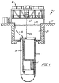
- FIG. 1 An important utilization of the apparatus and system of the invention is in conjunction with nuclear power facilities. During planned or scheduled shut-downs of these facilities wherein collateral activities such as refueling and the like are undertaken, weld seam inspection may be carried out. Preferably, this inspection is performed internally such that the water contained within the reactor vessel forms a shield serving to minimize radiation exposure to personnel.
- FIG. 1 an example of a boiling water reactor (BWR) component of a nuclear power facility is represented schematically at 10.
- the facility 10 is seen to include a reactor pressure vessel 12, the core of which at 14 is shown undergoing a refueling procedure during a planned shut-down. In thin regard, the top head or cap of the vessel 12 is removed and refueling access to the core is provided from a refueling bridge 16.
- BWR boiling water reactor
- Refueling bridge 16 is seen mounted at the refueling floor 18 of the facility 10 and extends over an upper, water-filled pool or refueling cavity 20.
- the water level within the cavity 20 is shown at 22.
- this cavity 20 may or may not be filled with water.
- the refueling activity is represented by a refueling manipulator 24 shown in the process of maneuvering a fuel assembly 26.
- a weld seam inspection manipulator assembly represented generally at 30, is seen to be in operation and under the control of control stations and the like. These control and data acquisition stations are located remotely from the vessel 12, for examplem at the refueling floor 18.
- a flexible control and communications cable 32 is seen extending from the manipulator 30 to sub-station cabinetry 34 at the refueling floor 18.
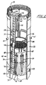
- the reactor vessel 12 is represented at a higher level of detail, particularly showing the structuring of manipulator assembly 30.
- the core again is represented at 14 and situated above the core are components typically encountered within such vessels 12, such as spargers 36 and 38, as well as a variety of nozzles as at 40-43.
- the core 14 is located at the belt-line region 46 of the vessel 12 and, also located at this general region, within a downcomer annulus are a sequence of elongated vertically oriented jet pumps as at 48-50.
- any manipulator such as at 30 must be configured to maneuver about these various components within the vessel 12.
- Manipulator 30 is configured having an upwardly disposed circumferential car 52 which partially spans and is driveably rotated about an upper guide ring 54, for example, by a position controlling motor 56.
- Supported from the circumferential car 52 is a vertically oriented mast 58 which extends to and is additionally movably supported upon a lower guide ring 60.
- Guide rings 54 and 60 are installed by inspection personnel in the course of preparing the vessel 12 for seam weld examination procedures.
- Vertically movable along the elongate edge of mast 58 is an upper search unit or head 62 carrying several of piezoelectric based ultrasonic testing transducers.
- the search unit 62 is manipulated by a vertical travel mechanism 64 and is in control and communication connection through a shielded cable 66 with circuitry developed in accordance with the instant invention within a protected enclosure (not shown) which may be mounted upon the mast 58 or circumferential car 52. From that circuitry, communication is further made via cabling as at 32 with the remote control and data acquisition facilities located, for example, on the refueling floor 18.
- Manipulator 30 further is capable of maneuvering an inspection assembly within the beltline region 46 of vessel 12 through the utilization of a linked belt 70 which is coupled to the lower portion of mast 58 through a swivel guide 72.
- a horizontal travel mechanism 74 which, in turn, supports a lower search unit or head 76 which is structured in the same manner as search unit 62.
- the horizontal travel mechanism is capable of moving vertically along one edge of the linked belt 70 and is further capable of maneuvering the search unit 76 horizontally.
- the linked belt assembly can be held against the vessel wall.
- Communication between the search unit 76 and circuitry employed with the instant invention is by shielded cable, such as a coaxial cable 78.
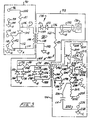
- a pulser and pre-amplifier circuit developed for the purpose of operating each of the piezoelectric transducers within search units 62 and 76 is revealed. These pulsers and pre-amplification circuits are located, as noted, in one of the linked belt 70 components or in the region of the mast 58.
- the circuit is generally configured having a pulser network or circuit represented at the boundary line 90; a transducer circuit represented within the boundary line 92; and a receiver circuit represented within the boundary line 94.
- Pulser network 90 functions to develop an excitation signal which is conveyed to transducer circuit 92. Rather than perform in conjunction with the relatively high level switching power supplies commonly encountered for such devices, network 90 performs in conjunction with a d.c. linear power supply which may be, for example, within about the 40 to 100 Vdc range. Such power supplies are readily available and exhibit lower electrical noise.
- the input to network 90 from this power supply is represented at terminals 96 and 98. Note that terminal 98 is seen coupled via line 100 to a ground designated A.
- Ground path A is a specific pulser circuit ground coupled with the instrumentation, for example, at the refueling floor 18 which also is associated with the noted linear power supply. This d.c.
- a power input of relatively lower level is applied via line 102 through a current limiting resistor R1 to the anode of a gated thyristor present as a silicon controlled rectifier (SCR) 104 and via line 106 in series to capacitor C1 and the primary winding 108 and thence via lines 110 and 112 to the noted ground path A.
- Line 112 additionally is seen to be connected with the cathode of SCR 104.
- the gate of SCR 104 at line 114 is seen directed to one terminal 116 of a control input which includes terminal 118 coupled, in turn, via line 120 to ground path A.
- a resistor R2 within line 110 extending to gate line 110 provides some load for the relatively low voltage level input trigger signal and also serves to prevent inadvertent gating on of the SCR 104 by shunting any spurious voltages (dv/dt) to ground.
- capacitor C1 is charged through resistor R1 in accordance with a predetermined time constant established by their parameter values.
- the charge level may reach, for example, a value of 100 volts.
- SCR 104 is gated into conduction and capacitor C1 discharges through the primary winding 108 of the uplser transformer 126 to ground A with a large negative pulse.
- Inductor winding 108 is the primary winding of a step-up transformer, the physically isolated secondary winding of which is shown Within transducer circuit 92 at 128.
- a typical turns ratio between winding 108 and winding 128 is 1:4 although the turns ratio may be any desired value suitable for the particular application.
- the negative going pulse asserted at primary winding 108 is inductively coupled and magnified into secondary winding 128. Accordingly, the more practical linear d.c. power supply becomes available for the requirement of transducer excitation.
- the transducer or input circuit as at 92 is operatively associated with a corresponding transducer of the search units.
- One such transducer is represented within the circuit 92 at 130.
- Communication between the transducer 130 and circuit 92 is by a shielded cable such as the schematically depicted coaxial cable 132.
- the shielding of cable 132 is connected to another distinct ground as depicted by line 134 and ground B.
- This ground tap is to an "input circuit and transducer" ground which is segregated from ground path A and may be the same ground path associated with reactor vessel 12.
- this transducer ground may be at the potential of reactor pressure vessel 12 and the manipulator 30 without adversely affecting the operation of the circuit.
- the output transducer 130 extends to the input network 138 of circuit 92 which incorporates blocking diodes D1 and D2, connected in and oppositely oriented, as represented at line 140 to secondary winding 128 and thence as represented at line 142 to the isolated transducer ground B.
- blocking diodes D1 and D2 permit conduction during the initial negative excursion of the pulse witnessed at winding 128 but block any interaction with the pulser network 90 thereafter.
- the transducer 130 be excited with a half sinewave or half cycle pulse to achieve its excitation at the center value of its resonant frequency. This permits its most efficient excitation.
- the length of the submerged coaxial cable 132 will not exceed about two meters, the variable distance from the submerged circuit of Fig. 3 and search units at 62 or 74.
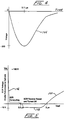
- Waveform 144 is that employed, for example for driving a 2.25 MHz transducer.
- the pulse shape 144 in general, is determined by the size of capacitor C1.
- the circuitry is tuned to the characteristics of the transducer as at 130 by adjusting the size of C1.
- the voltage on the circuit at the input terminals is adjusted to set the pulse height
- capacitor C1 will be selected in a range of about 1,000 picofarads to 20,000 picofarads.
- pulser network 90 in conventional transducer drive systems, where SCRs are employed for switching purposes, they are turned off by the precedure of current starvation.
- SCRs inductive coupling between network 90 and circuit 92
- Blocking diodes D1 and D2 promote this development of reverse EMF. That reverse EMF will occur across SCR 104 for an interval of time and thus positively turn it off or commutate it
- a typical waveform showing this activity is represented at 146, 148, and 150 in association with the earlier-noted exemplary power supply of 100 volts d.c.
- Waveform component 146 represents the conducting phase of SCR 104 in response to a gating or trigger signal input. At about 0.2 microseconds, there is seen to occur a current starvation whereupon, as represented at waveform component 148 extending substantially between 0.2 microseconds and 5 microseconds, the SCR 104 is reverse biased or commutated off. This commutation length, is of a relatively significant interval assuring the off-state condition. Following that interval, a recovery phase ensues wherein capacitor C1 is recharged substantially to supply voltage and the SCR 104 remains off in keeping with its conventional operational characteristics.
- the pulse repetition rate as developed by pulser network 90 is derived with to the time constant evolved between resistor R1 and capacitor C1. Generally, by adjusting the size or resistance value of resistor R1 an optimum desired performance may be evolved. Typically, a pulse repetition rate of 100 to 5,000 pulses per second is selected. With the arrangement shown, a variety of advantages accrue with the circuit Through the use of a step-up transformer 126 the demands for the power supply diminish to the extent that readily available low voltage llinear power supply with low noise characteristics may be used.
- the transformer coupling between the primary winding 108 and secondary winding 128 developed between network 90 and circuit 92 functions to, in turn, isolate the ground path A from ground path B.
- Transducer 130 when used in a pulse-echo mode, will respond to this received or reflected pulse and generate a response signal. Alternately, where a "pitch-catch" transducer arrangement is utilized, a separate transducer will be employed for the reception of the reflected or return pulse. Blocking diodes D1 and D2 function to isolate the output network 160 during this reception interval. As the faint return signal is received, it is transmitted from the transducer 130 to line 136.
- the signal will be in the 200 or 300 millivolt range or lower.
- This signal then is directed via line 162 and resistor R3 to line 164.
- Resistor R3 functions to provide a damping resistance to the excitation pulses asserted upon circuit 92, as well as to provide an impedance match with respect to the coaxial cable 132.
- Line 164 is seen directed to diode D3, the cathode of which is coupled via line 166 to ground path B.
- diode D4 Also associated with diode D3 in reversed fashion is diode D4 which is seen coupled to line 164 through line 168 and to line 166 through line 170.
- Also coupled to line 164 is line 172, resistor R4 and line 174.
- line 176 Coupled to line 174 is line 176 which, in turn, is directed to the cathode of diode D5, the anode of which at line 178 is coupled to the earlier-noted ground path B.
- a reverse oriented diode D6 also is coupled via line 180, line 176 and by line 182 to line 178.
- Back-to-back diodes D3, D4 and D5, D6 function to shunt the large excitation pulse initiated from pulsing network 90 to ground path B.
- Resistor R4 positioned between these diode pairs provides a second level of isolation protecting the receiver circuit 94.
- any diversion of such signal is blocked by the diode pairs D3, D4 and D5, D6, and the return signal is directed via line 174 to the primary winding 184 of a step-up transformer 186.
- the opposite side of winding 184 is directed via line 188 to ground path B.
- the secondary winding 190 of transformer 186 responds to the applied response signal, which now will be stepped up to a higher voltage value.
- the turns ratio between primary winding 184 and secondary winding 190 may be 1:4.
- This stepped-up voltage signal is applied via line 192 to the gate terminal of a field effect transistor (FET) 194 which serves as an amplification stage of the receiver circuit 94.
- FET field effect transistor
- the opposite side of secondary winding 190 is coupled via lines 196 and 198 to another, segregated "receiver" ground path, C.
- This path will extend, for example, to the instrumentation power supply associated with circuit 94.
- Line 198 is seen coupled to line 192 and incorporates a resistor R5 which will be selected having relatively higher value, for example in the range of about 100 Kiloohms. Resistor R5 functions to establish bandwidth, as well as participates in an impedance matching function. It may be observed that through the employment of magnetic isolation provided by transformer 186, the ground path C is isolated from ground path B as well as from ground path A. This serves to substantially abate noise and improve the signal generating capability of the entire inspection system.
- transformer 186 Of particular importance in the utilization of transformer 186 is the noise resistance characteristic of FET device 194. These devices are, in themselves, relatively quiet with respect to noise generation. However, the step-up performance of transformer 186 functions to provide an equivalent match of the noise resistance characteristics of the FET 194 with the impedance exhibited by transducer circuit 92, for example, as exhibited by the primary circuit of transformer 186 including resistors R3 and R4. That impedance essentially is magnified to a correspondence or equivalence with the noise resistance characteristic of device 194.
- Receiver circuit 94 is somewhat conventional in its construction, FET 190 performs in conjunction with a current amplification and filtering function including inductive windings or chokes 200 and 202 within respective lines 204 and 206.
- winding 200 extends via line 208 to a power supply input terminal 210.
- the corresponding grounding terminal 212 is coupled via line 214 to ground path C and a filter capacitor C3 coupled intermediate lines 216 and 218 also is directed to ground path C.
- the opposite electrode of FET 194 is coupled via line 206, resistor R6 and line 220 to one side of winding 202, the opposite side of which at line 222 extends to a power supply terminal 224 of opposite polarity to that at 210.
- the ground terminal corresponding to terminal 224 is shown at 226 coupled via line 228 to ground path C.
- a filter capacitor C4 is seen coupled to intermediate lines 230 and 232 extending, in turn, to respective lines 220 and 228.
- a power input of one polarity for example, +8Vdc
- a negative input power supply for example -8Vdc
- the resultant amplified signal is provided at lines 230 and 232 through coupling capacitor C2 to terminal 234, while the corresponding output ground is provided at terminal 236 which, in turn, is coupled to ground path C via line 238.
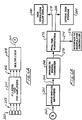
- a bock diagrammatic representation of the components of the apparatus at hand which are maintained under water in reasonably close adjacency with the search units 62 and 76 is revealed.
- the length of communication between the circuits and the circuitry thus far described will be about 2 meters.
- an array of transducers is represented at 250 having cable inputs represented by corresponding line array 252 to pulser and preamplifier functions represented at block 254.
- This function, as represented at block 254, corresponds with the circuit of Fig. 3, one such circuit being provided for each transducer.
- the resultant response output signals as well as triggering inputs for transducer selection are promulgated at lead array 256 from a multiplexing function represented at block 258.
- This multiplexing function then conveys the resultant signals to a data acquisition and control facility as represented by line 260 leading to node X.
- a data acquisition and control facility as represented by line 260 leading to node X.
- a data acquisition and control facility as represented by line 260 leading to node X.
- Several multiplexers may be used to achieve a configuration with as many transducers as may be desired.
- Block 264 provides a linear and logarithmic amplification function, whereupon resultant data signals are directed as represented by line 266 to an analog-to-digital conversion function represented at block 268. Following conversion, the resultant digital data then are directed, as represented by line 270 and block 272 to a real-time workstation for operator evaluation and appropriate treatment.
- the workstation represented at block 272 also is interfaced to the controller for manipulator 30 as represented by line 274 and block 276. Data also are displayed at a high resolution color display as represented by line 278 and block 280. Additionally, the substantial volume of data evolved during the examination procedures at hand are stored, through the utilization of optical disk media as represented by line 282 and block 284.
Landscapes
- Physics & Mathematics (AREA)
- General Health & Medical Sciences (AREA)
- Immunology (AREA)
- Chemical & Material Sciences (AREA)
- Analytical Chemistry (AREA)
- Biochemistry (AREA)
- Health & Medical Sciences (AREA)
- General Physics & Mathematics (AREA)
- Life Sciences & Earth Sciences (AREA)
- Pathology (AREA)
- Acoustics & Sound (AREA)
- Engineering & Computer Science (AREA)
- Mechanical Engineering (AREA)
- Monitoring And Testing Of Nuclear Reactors (AREA)
- Investigating Or Analyzing Materials By The Use Of Ultrasonic Waves (AREA)
Applications Claiming Priority (3)
| Application Number | Priority Date | Filing Date | Title |
|---|---|---|---|
| US694730 | 1991-05-02 | ||
| US07/694,730 US5303591A (en) | 1991-05-02 | 1991-05-02 | Ultrasonic inspection system with improved pulser and receiver circuits |
| EP92303955A EP0522685B1 (de) | 1991-05-02 | 1992-04-30 | Ultraschallprüfvorrichtung mit Impulsgeber- und Empfangsschaltung |
Related Parent Applications (2)
| Application Number | Title | Priority Date | Filing Date |
|---|---|---|---|
| EP92303955.6 Division | 1992-04-30 | ||
| EP92303955A Division EP0522685B1 (de) | 1991-05-02 | 1992-04-30 | Ultraschallprüfvorrichtung mit Impulsgeber- und Empfangsschaltung |
Publications (2)
| Publication Number | Publication Date |
|---|---|
| EP0735367A2 true EP0735367A2 (de) | 1996-10-02 |
| EP0735367A3 EP0735367A3 (de) | 1996-11-13 |
Family
ID=24790048
Family Applications (3)
| Application Number | Title | Priority Date | Filing Date |
|---|---|---|---|
| EP96109155A Withdrawn EP0741292A3 (de) | 1991-05-02 | 1992-04-30 | Ultraschallprüfvorrichtung mit verbesserter Impulsgeber- und Empfangsschaltung |
| EP96109156A Withdrawn EP0735367A3 (de) | 1991-05-02 | 1992-04-30 | Ultraschallprüfvorrichtung mit verbesserter Impulsgeber- und Empfangsschaltung |
| EP92303955A Expired - Lifetime EP0522685B1 (de) | 1991-05-02 | 1992-04-30 | Ultraschallprüfvorrichtung mit Impulsgeber- und Empfangsschaltung |
Family Applications Before (1)
| Application Number | Title | Priority Date | Filing Date |
|---|---|---|---|
| EP96109155A Withdrawn EP0741292A3 (de) | 1991-05-02 | 1992-04-30 | Ultraschallprüfvorrichtung mit verbesserter Impulsgeber- und Empfangsschaltung |
Family Applications After (1)
| Application Number | Title | Priority Date | Filing Date |
|---|---|---|---|
| EP92303955A Expired - Lifetime EP0522685B1 (de) | 1991-05-02 | 1992-04-30 | Ultraschallprüfvorrichtung mit Impulsgeber- und Empfangsschaltung |
Country Status (4)
| Country | Link |
|---|---|
| US (2) | US5303591A (de) |
| EP (3) | EP0741292A3 (de) |
| JP (1) | JPH05172797A (de) |
| DE (1) | DE69218055D1 (de) |
Families Citing this family (12)
| Publication number | Priority date | Publication date | Assignee | Title |
|---|---|---|---|---|
| US5511424A (en) * | 1994-02-15 | 1996-04-30 | The Babcock & Wilcox Company | Remote preamplifier and impedance matching circuit for electromagnetic acoustic transducer |
| DE4431625C1 (de) * | 1994-09-07 | 1996-03-07 | Siemens Ag | Vorrichtung zur zerstörungsfreien Prüfung des Kernmantels von Siedewasser-Kernreaktoranlagen |
| US5460180A (en) * | 1994-09-30 | 1995-10-24 | Siemens Medical Systems, Inc. | Connection arrangement and method of operation of a 2D array for phase aberration correction |
| JPH10123235A (ja) * | 1996-10-15 | 1998-05-15 | Denso Corp | 超音波センサ及び車両用障害物検出装置 |
| EP1042653A1 (de) | 1997-12-23 | 2000-10-11 | Simmonds Precision Products Inc. | Ultraschall-flüssigkeitsmesssystem |
| RU2224247C1 (ru) * | 2003-03-27 | 2004-02-20 | ЗАО "Нефтегазкомплектсервис" | Ультразвуковой дефектоскоп (варианты) |
| US7104131B2 (en) * | 2004-03-17 | 2006-09-12 | Battelle Energy Alliance, Llc | Ultrasonic pulser-receiver |
| CN103226207B (zh) * | 2012-01-25 | 2017-11-10 | 英洛瓦(天津)物探装备有限责任公司 | 电源模块中的模拟 |
| US9232933B2 (en) * | 2013-02-01 | 2016-01-12 | Kabushiki Kaisha Toshiba | Transformer-based multiplexer for ultrasound imaging system and method |
| US9322720B2 (en) * | 2013-02-25 | 2016-04-26 | U.S. Department Of Energy | Use of aluminum nitride to obtain temperature measurements in a high temperature and high radiation environment |
| US9461709B2 (en) | 2014-06-30 | 2016-10-04 | Intel Corporation | Methods and systems for server power line communication |
| CN109888935B (zh) * | 2019-03-11 | 2023-10-24 | 南华大学 | 一种电网隔离取电方法及电路 |
Family Cites Families (12)
| Publication number | Priority date | Publication date | Assignee | Title |
|---|---|---|---|---|
| US3817089A (en) * | 1971-06-30 | 1974-06-18 | Interscience Res Inst | Rotating probe high data acquistion rate apparatus |
| US3982425A (en) * | 1974-01-14 | 1976-09-28 | Rockwell International Corporation | Ultrasonic inspection system |
| FR2278217A1 (fr) * | 1974-07-10 | 1976-02-06 | Schlumberger Prospection | Transducteur acoustique |
| US4052887A (en) * | 1976-04-05 | 1977-10-11 | Standard Oil Company | Ultrasonic testing device and method |
| DE2629562C2 (de) * | 1976-07-01 | 1982-06-24 | Danfoss A/S, 6430 Nordborg | Gerät zur Ultraschallmessung |
| US4281404A (en) * | 1979-08-27 | 1981-07-28 | Morrow Electronics, Inc. | Depth finding apparatus |
| JPS58187916A (ja) * | 1982-04-28 | 1983-11-02 | West Electric Co Ltd | 超音波測距装置 |
| GB8727070D0 (en) * | 1987-11-19 | 1987-12-23 | Nat Res Dev | Electrical drive circuits |
| US4995010A (en) * | 1989-07-21 | 1991-02-19 | Johnson Fishing, Inc. | Depth finding-trolling system |
| DE69019289T2 (de) * | 1989-10-27 | 1996-02-01 | Storz Instr Co | Verfahren zum Antreiben eines Ultraschallwandlers. |
| US5145637A (en) * | 1990-05-24 | 1992-09-08 | General Electric Company | Incore housing examination system |
| US5449958A (en) * | 1994-07-08 | 1995-09-12 | The Babcock & Wilcox Company | Diode expander for electromagnetic acoustic transducer electronics |
-
1991
- 1991-05-02 US US07/694,730 patent/US5303591A/en not_active Expired - Fee Related
-
1992
- 1992-04-27 JP JP4107148A patent/JPH05172797A/ja not_active Withdrawn
- 1992-04-30 EP EP96109155A patent/EP0741292A3/de not_active Withdrawn
- 1992-04-30 DE DE69218055T patent/DE69218055D1/de not_active Expired - Lifetime
- 1992-04-30 EP EP96109156A patent/EP0735367A3/de not_active Withdrawn
- 1992-04-30 EP EP92303955A patent/EP0522685B1/de not_active Expired - Lifetime
-
1993
- 1993-06-22 US US08/080,794 patent/US5495765A/en not_active Expired - Fee Related
Also Published As
| Publication number | Publication date |
|---|---|
| EP0522685A3 (de) | 1993-04-14 |
| US5495765A (en) | 1996-03-05 |
| US5303591A (en) | 1994-04-19 |
| EP0735367A3 (de) | 1996-11-13 |
| JPH05172797A (ja) | 1993-07-09 |
| EP0741292A3 (de) | 1996-11-13 |
| EP0522685B1 (de) | 1997-03-12 |
| EP0522685A2 (de) | 1993-01-13 |
| DE69218055D1 (de) | 1997-04-17 |
| EP0741292A2 (de) | 1996-11-06 |
Similar Documents
| Publication | Publication Date | Title |
|---|---|---|
| US5495765A (en) | Ultrasonic inspection system with improved electrical isolation scheme using step-up transformers | |
| US6282106B2 (en) | Power supply for an electrostatic precipitator | |
| EP0104928B1 (de) | Ultraschallsichtgerät zur Diagnostik mit variabler Tiefenschärfe | |
| JPS5819061B2 (ja) | チヨウオンパケンサソウチ | |
| CA2078524A1 (en) | Nuclear reactor vessel inspection system and method with remote transducer positioning | |
| WO1996018112A1 (en) | Method and device for locating partial discharges in an electric high-voltage apparatus | |
| ES8401634A1 (es) | "aparato para detectar grietas en el balancin de bomba de chorro de un sistema de bombas de chorro de reactor nuclear". | |
| US6748803B1 (en) | Liquid measurement system and shared interface apparatus for use therein | |
| US5144592A (en) | Ultrasonic transmission-reception system | |
| JP4455685B2 (ja) | 受信信号から所定の周波数の信号を除去するシステム | |
| US4391144A (en) | Ultrasonic test probe | |
| US4745359A (en) | Method and apparatus for determining polarity of a capacitor | |
| RU2224247C1 (ru) | Ультразвуковой дефектоскоп (варианты) | |
| SU1490626A1 (ru) | Электромагнитно-акустическое устройство дл дефектоскопии изделий из ферромагнитных материалов | |
| RU31281U1 (ru) | Ультразвуковое сканирующее устройство (варианты) | |
| Filus | An efficient driver for electromagneto-acoustic transducers with a switch-mode high voltage supply | |
| SU1555663A1 (ru) | Приемо-передающее устройство ультразвукового дефектоскопа | |
| Bohn et al. | Apparative developments for inservice inspections of reactor pressure vessels | |
| SU410776A1 (de) | ||
| KR810000193B1 (ko) | 불완전한 핵연료체를 탐지하는 장치 | |
| SU1696994A1 (ru) | Электроакустический тракт ультразвукового дефектоскопа | |
| KR810000194B1 (ko) | 불완전한 핵연료체를 탐지하는 방법 | |
| Dykes | An advanced ultrasonic system for BWR vessel weld inspection | |
| Eylon et al. | Electron beam, 3.5 MV, 2 kA injector diode diagnostics for the DARHT facility | |
| SE500470C2 (sv) | Elstängselapparat med dämpning av frekvenser över en gränsfrekvens |
Legal Events
| Date | Code | Title | Description |
|---|---|---|---|
| PUAI | Public reference made under article 153(3) epc to a published international application that has entered the european phase |
Free format text: ORIGINAL CODE: 0009012 |
|
| PUAL | Search report despatched |
Free format text: ORIGINAL CODE: 0009013 |
|
| AC | Divisional application: reference to earlier application |
Ref document number: 522685 Country of ref document: EP |
|
| AK | Designated contracting states |
Kind code of ref document: A2 Designated state(s): CH DE ES LI SE |
|
| AK | Designated contracting states |
Kind code of ref document: A3 Designated state(s): CH DE ES LI SE |
|
| STAA | Information on the status of an ep patent application or granted ep patent |
Free format text: STATUS: THE APPLICATION IS DEEMED TO BE WITHDRAWN |
|
| 18D | Application deemed to be withdrawn |
Effective date: 19970515 |