EP0735318A2 - Kraftstoff-Einspritzdüse mit verstellbarer Geometrie - Google Patents
Kraftstoff-Einspritzdüse mit verstellbarer Geometrie Download PDFInfo
- Publication number
- EP0735318A2 EP0735318A2 EP96301783A EP96301783A EP0735318A2 EP 0735318 A2 EP0735318 A2 EP 0735318A2 EP 96301783 A EP96301783 A EP 96301783A EP 96301783 A EP96301783 A EP 96301783A EP 0735318 A2 EP0735318 A2 EP 0735318A2
- Authority
- EP
- European Patent Office
- Prior art keywords
- air
- fuel
- variable geometry
- mixing region
- combustion chamber
- Prior art date
- Legal status (The legal status is an assumption and is not a legal conclusion. Google has not performed a legal analysis and makes no representation as to the accuracy of the status listed.)
- Granted
Links
- 239000000446 fuel Substances 0.000 title claims abstract description 76
- 238000002485 combustion reaction Methods 0.000 claims abstract description 38
- 238000011144 upstream manufacturing Methods 0.000 claims abstract description 18
- 239000000203 mixture Substances 0.000 claims abstract description 12
- 239000007921 spray Substances 0.000 claims description 3
- 230000000694 effects Effects 0.000 description 7
- 239000007789 gas Substances 0.000 description 6
- 238000001816 cooling Methods 0.000 description 2
- 238000003491 array Methods 0.000 description 1
- 238000000889 atomisation Methods 0.000 description 1
- 230000008033 biological extinction Effects 0.000 description 1
- 239000000567 combustion gas Substances 0.000 description 1
- 238000010790 dilution Methods 0.000 description 1
- 239000012895 dilution Substances 0.000 description 1
- 238000002347 injection Methods 0.000 description 1
- 239000007924 injection Substances 0.000 description 1
- 238000005192 partition Methods 0.000 description 1
- 230000001681 protective effect Effects 0.000 description 1
- 239000000779 smoke Substances 0.000 description 1
Images


Classifications
-
- F—MECHANICAL ENGINEERING; LIGHTING; HEATING; WEAPONS; BLASTING
- F23—COMBUSTION APPARATUS; COMBUSTION PROCESSES
- F23R—GENERATING COMBUSTION PRODUCTS OF HIGH PRESSURE OR HIGH VELOCITY, e.g. GAS-TURBINE COMBUSTION CHAMBERS
- F23R3/00—Continuous combustion chambers using liquid or gaseous fuel
- F23R3/02—Continuous combustion chambers using liquid or gaseous fuel characterised by the air-flow or gas-flow configuration
- F23R3/26—Controlling the air flow
-
- F—MECHANICAL ENGINEERING; LIGHTING; HEATING; WEAPONS; BLASTING
- F23—COMBUSTION APPARATUS; COMBUSTION PROCESSES
- F23C—METHODS OR APPARATUS FOR COMBUSTION USING FLUID FUEL OR SOLID FUEL SUSPENDED IN A CARRIER GAS OR AIR
- F23C7/00—Combustion apparatus characterised by arrangements for air supply
- F23C7/008—Flow control devices
Definitions
- This invention relates to a combustion chamber head assembly with variable geometry fuel injector means for a gas turbine engine combustor.
- the invention concerns a fuel injector having airflow control means operative to vary combustor airflow in accordance with engine operating conditions.
- Fuel injectors used in the combustion systems of modern gas turbine engines are usually of the air-spray (or air-blast) atomiser type. These devices are designed to bring together controlled amounts of air and fuel to achieve a well distributed air-fuel mixture for engine combustor entry at a desired air-fuel ratio. Fuel atomisation is achieved by exposing the fuel to a high velocity airflow supplied from the engine compressor. It is generally preferred that the airflow is caused to swirl to increase the relative velocity between the air and the fuel prior to combustor entry. This provides for more efficient burning with the resultant effect of reduced combustor emissions.
- swirl vanes are provided to create the necessary swirl effect.
- the vanes are arranged in arrays disposed around a central fuel delivery nozzle and/or coaxially with a ring of fuel discharge apertures.
- the vanes may define radially inflowing air swirl devices or alternatively axial flow devices. In both arrangements the airflow through the injector is determined by the effective flow area of the airflow passages between the vanes.
- the selection of the portion of combustor air that is to enter the combustor through the swirl devices is often a compromise between desired combustor performance at full power conditions, where it is preferable to operate with a relatively weak air-fuel mixture to minimise smoke emissions, and desired combustor performance at low power conditions where there is a requirement to avoid weak extinction.
- With fixed geometry devices there is a limit to the operational range of the injectors, and in order to obtain satisfactory performance at low power conditions it has been the practice to limit injector air-fuel ratios at high power conditions.
- staged combustors typically include a dedicated pilot stage combustion zone which is optimised for low emission combustion at low power low temperature settings, and a main stage combustion zone which is optimised for low emission combustion at high power high temperature settings. Fuel is fed to dedicated pilot stage fuel injectors during low power operation, and additionally to dedicated main stage injectors during high power operation. During low power operation fuel to the main stage injectors is cut off and all fuel goes to the pilot resulting in improved combustor stability.
- staged combustors is that they add to the overall weight and mechanical complexity of the engine.
- variable geometry fuel injectors Another approach has been to control the airflow through the injectors by making the injectors variable geometry.
- a number of variable geometry fuel injectors have been proposed wherein the airflow through the injector is controlled by a movable control ring or sleeve disposed about the outer periphery of the vanes. Apertures formed in the control ring (or sleeve) cooperate with the airflow passages between the vanes in such a manner to regulate the airflow entering the injector through the vanes.
- An example of an injector of this type is disclosed in International Patent Application W092/17736.
- the injector disclosed in this reference comprises a pair of axially adjacent swirl devices, one of which is of the variable geometry type having an axially translatable sleeve element disposed about it's outer periphery, and one which is fixed.
- variable geometry devices A problem associated with this and other variable geometry devices is that as the airflow through the injector is restricted there is a resultant increase in combustion chamber pressure loss. The effect of this is to cause the engine compressor to operate closer to a surge condition and the airflow through engine compressor bleed systems to increase.
- injectors are provided with one or more fixed geometry swirl devices in addition to at least one variable geometry device, as in W092/17736 above, there is an additional problem of the airflow through the fixed geometry device increasing as the combustion pressure loss increases. This has this effect of negating, at least in part, the airflow reduction intended.
- variable geometry fuel injector which overcomes the problems of the prior art.
- the invention has for an objective a variable geometry fuel injector which has a combustion chamber pressure loss characteristic consistent with that of a fixed geometry device.
- a combustion chamber head assembly with variable geometry fuel injector means for a gas turbine engine comprising a combustor head defining an enclosed volume separated on its downstream side from a combustion region by an endwall which is pierced by a multiplicity of apertures including at least one fuel-air mixture aperture and a plurality of air-only apertures, and at least one fuel injector assembly including means defining a fuel-air mixing region opening through the fuel-air mixture aperture into the combustion region, a fuel nozzle which, in operation, sprays fuel into the fuel-air mixing region, and airflow control means having a first flow passage for admitting air into the fuel-air mixing region and a second passage including a movable diverter member for selectively diverting air entering the second passage to exit either into the mixing region or via the enclosed combustor head volume into the plurality of air-only apertures whereby airflow into the mixing region may be varied.
- the air passing through the vanes is directed into a cavity disposed on the upstream side of the combustion chamber.
- the cavity is divided from the combustion chamber by a combustion chamber endwall, and the endwall is apertured to provide the air-fuel and air-only outlets.
- the air-fuel and air-only outlets are spaced apart so that air entering the combustion chamber through the air-only outlet or outlets has substantially no effect on the combustion chamber air-fuel ratio immediately downstream of the air-fuel outlet.
- the flow control means may comprise an axially translatable sleeve which co-operates with a coaxial annular flange member to define an annular flow boundary between the air-fuel mixing region and the cavity.
- the sleeve comprises an inner annular wall member which forms part of the flow boundary, and an adjoining outer annular wall which forms part of a sleeve valve arrangement for directing air exiting the vanes to the alternative air-fuel and air-only flow outlets.
- the outer wall member may be provided with a plurality of circumferentially spaced apertures through which air exiting the vanes passes as the sleeve is progressively moved to restrict the air entering the mixing region.
- a variable geometry air-fuel injector 10 positioned at the upstream end of a gas turbine engine combustor 12.
- a plurality of such injectors are circumferentially spaced around the combustor 12 for delivery of an air-fuel mixture to a primary combustion zone 13.
- Figure 1 shows the sectional detail of one injector, all the injectors in the system being identical.
- the surrounding engine detail such as elements of the engine compressor and turbine which lie adjacent the combustor, is omitted for clarity.
- a portion of incoming air from the engine compressor (not shown, but to the left of the drawing in Figure 1) is directed to the injectors 10 where it is mixed with fuel to form a vaporised air-fuel mixture.
- This mixture enters the upstream primary combustion zone 13 where it is burnt.
- the combustion gases then enter a downstream dilution or secondary zone (not shown) where additional air from the engine compressor is added prior to expansion through the engine turbine (also not shown, but to the right of the drawing in Figure 1).
- the combustor shown is of a generally conventional configuration and includes a pair of radially spaced annular sidewall members 14 and 16 which are coaxially disposed about a main engine axis 18.
- the sidewalls are connected at their upstream end by means of an aerodynamically shaped combustor head portion 20 and an upstream combustor bulkhead 22.
- the bulkhead extends radially between the sidewalls to provide an annular partition between an upstream air cavity 24 and a downstream combustion chamber region 26.
- a protective heatshield 28 is mounted on the downstream face of the bulkhead 22 to provide thermal shielding from combustion temperatures.
- the heatshield has an annular configuration made up of a plurality of abutting heatshield segments which are bolted in abutting relationship to the bulkhead 22.
- the segments which are of substantially identical form, extend both radially towards the inner and outer walls 14 and 16 of the combustor, and circumferentially towards adjacent segments to provide a fully annular shield.
- the bulkhead is provided with a plurality of circumferentially spaced apertures 30 for air-fuel entry to the combustion chamber 26, and a like plurality of apertures 32 and 34 for air-only entry.
- the air-fuel apertures 30 are positioned mid-way between the inner and outer combustor walls 14 and 16 and align with a corresponding series of apertures 31 formed in the upstream head portion 20.
- the air-only apertures 32 and 34 lie adjacent the combustor walls at the radially inner and outer bulkhead extremities.
- the heatshield segments, which are each associated with an adjacent one of the air-fuel apertures 30, are similarly provided with air-fuel entry apertures 36 which align with the bulkhead apertures 30 in the combustor assembly.
- the segments are each spaced a short distance from the bulkhead to create a series of under-segment chambers 38.
- Each segment is spaced from the bulkhead by an annular flange 40 formed around the air-fuel aperture 36.
- the chambers 38 are each adapted to receive a supply of cooling air for tile cooling through a further series of bulkhead apertures 42 formed around the air-fuel entry apertures 30.
- the cavity 24 is vented at a number of positions 25 to receive a portion of the compressor airflow for supply to the under tile chambers 38.
- Each injector has a generally cylindrical configuration and comprises a pair of axially spaced air swirl devices 44 and 46 disposed about a main injector axis 48, a central fuel delivery nozzle 50 aligned substantially along that axis, and an axially extending downstream cylindrical flange portion 52 which locates the injector in a respective one of the combustor apertures 31.
- the fuel delivery nozzle 50 is positioned at the distal end of a fuel delivery arm 51 suspended from surrounding engine casing structure (not shown).
- the first of the swirl devices 44 comprises a plurality of circumferentially spaced swirl vanes 54 which define a first series of radially inflowing air-inlet passages 56.
- the second device 46 comprises a like plurality of swirl vanes 58 which define an adjacent series of inlet passages 60.
- the first and second swirl devices define first and second airflow inlets to a central air-fuel mixing region 68 downstream of the fuel nozzle 50.
- the first series of vanes 54 are disposed between an upstream injector end wall 62 and a profiled annular flow divider 64.
- the second set of vanes 58 are disposed in a similar manner between the flow divider 64 and the upstream extremity of the cylindrical flange 52.
- the end wall 62 and flow divider 64 define opposing sides of a common flow path 66 which extends from the vane inlet passages 56 to the air-fuel mixing region 68.
- the flow path 66 has an arcuate profile which is determined by the correspondingly shaped interior end wall and upstream flow divider surfaces 70 and 72.
- the shape of the flow path 66 is such that the air entering the injector through the vanes 56 is turned through 90 degrees before entering the air-fuel mixing region 68.
- An arcuate flow path 74 is similarly defined on the downstream side of the flow divider 64. This flow path extends in a similar manner between the vanes 58 and the air-fuel mixing region 68.
- the shape of the flow path 74 corresponds to that of the adjacent flow path 66 so that air entering the injector through the vanes 56 is caused to exit in the direction of the injector axis 48.
- downstream boundary of the injector flow path 74 is provided by an upstream portion of a axially moveable flow control ring 78.
- the flow control ring comprises a pair of radially spaced annular wall members 80 and 82 which are joined at their respective upstream ends along a common side edge 83.
- the inner wall member 80 defines an annular airflow boundary between the air-fuel mixing region 68 and the surrounding airflow cavity 24.
- the inner wall 80 includes a downstream cylindrical wall section 84 which has a stepped outer surface for cooperation with an overlapping portion of a cylindrical flange 86 extending from the bulkhead aperture 30, and a profiled upstream portion 88 which is shaped in accordance with the downstream surface of the flow divider 64.
- the outer wall 82 includes a main cylindrical portion 90 which lies adjacent the injector flange 52 and a radially spaced cylindrical flange 92.
- the flange 92 is positioned at the downstream end of the cylinder in coaxial spaced relation so as provide an annular recess 94 for receiving the injector flange 52.
- the recess 94 provides for location of the control ring with respect to the injector body and in addition provides a guide for the movable ring along the injector axis.
- a plurality of circumferentially spaced airflow apertures 96 are distributed around the cylinder 90 immediately downstream of the adjoining side edge 83. These apertures form the side openings of a sleeve valve arrangement which is operative to direct the flow exiting the vane passages 60 to selective alternative regions.
- the control ring 78 which forms the movable part of the sleeve valve arrangement is connected to a rotatable input shaft 98.
- the shaft extends radially outward from the injector 10 through a bush 100 located in the combustor head 20.
- the shaft extends in the radial direction of the engine and is connected at it's radially outermost end to a unison ring (not shown) linking all the injectors 10 for coordinated operation.
- the radially innermost end of the shaft 98 is attached to one end of a actuating lever 102.
- the lever has a elongate slot 104 which is adapted to receive an upstanding pin 106 secured to the cylindrical flange 92 at the 12 O'clock position of the ring.
- the shaft is offset from the pin so that as the shaft rotates the control ring is caused to translate.
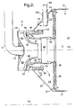
- the control ring is movable between the positions shown in Figures 1 and 2. In the position of Figure 1 the injector is configured for high power engine operation.
- the control ring 78 is positioned as far rearward as the arrangement will allow.
- the upstream edge of the ring is aligned with the downstream extremity of the downstream injector vane passages 60.
- the apertures 96 at the upstream end of the ring are disposed adjacent the cylindrical flange 52.
- the ring effectively seals the cavity 24 from the airflow through the vanes. In this position all the air passing through the vane passages 56 and 60 enters the mixing region 68 for discharge as an air-fuel mixture to the primary combustion region 13.
- the injector described provides for greater operational flexibility since there is little or no change in effective injector air inlet area during flow modulation.
- the inlet flow area presented to the incoming compressor airflow by the vane passages 56 and 60 remains constant regardless of control ring position. The only effect the control ring has is to alter the proportion of the incoming air which enters the air-fuel mixing region.
Landscapes
- Engineering & Computer Science (AREA)
- Chemical & Material Sciences (AREA)
- Combustion & Propulsion (AREA)
- Mechanical Engineering (AREA)
- General Engineering & Computer Science (AREA)
- Gas Burners (AREA)
Applications Claiming Priority (2)
| Application Number | Priority Date | Filing Date | Title |
|---|---|---|---|
| GB9506116A GB2299399A (en) | 1995-03-25 | 1995-03-25 | Variable geometry air-fuel injector |
| GB9506116 | 1995-03-25 |
Publications (3)
| Publication Number | Publication Date |
|---|---|
| EP0735318A2 true EP0735318A2 (de) | 1996-10-02 |
| EP0735318A3 EP0735318A3 (de) | 1998-10-28 |
| EP0735318B1 EP0735318B1 (de) | 2000-11-15 |
Family
ID=10771886
Family Applications (1)
| Application Number | Title | Priority Date | Filing Date |
|---|---|---|---|
| EP96301783A Expired - Lifetime EP0735318B1 (de) | 1995-03-25 | 1996-03-15 | Kraftstoff-Einspritzdüse mit verstellbarer Geometrie |
Country Status (5)
| Country | Link |
|---|---|
| US (1) | US5664412A (de) |
| EP (1) | EP0735318B1 (de) |
| CA (1) | CA2172444A1 (de) |
| DE (1) | DE69610938T2 (de) |
| GB (1) | GB2299399A (de) |
Cited By (3)
| Publication number | Priority date | Publication date | Assignee | Title |
|---|---|---|---|---|
| EP1375891A1 (de) * | 1997-07-15 | 2004-01-02 | New Power Concepts LLC | Sammelrohr für eine Stirlingmaschine |
| WO2007060216A1 (en) * | 2005-11-26 | 2007-05-31 | Siemens Aktiengesellschaft | A combustion apparatus |
| FR3011317A1 (fr) * | 2013-10-01 | 2015-04-03 | Snecma | Chambre de combustion pour turbomachine a admission d'air homogene au travers de systemes d'injection |
Families Citing this family (48)
| Publication number | Priority date | Publication date | Assignee | Title |
|---|---|---|---|---|
| DE4220060C2 (de) | 1992-06-19 | 1996-10-17 | Mtu Muenchen Gmbh | Einrichtung zur Betätigung einer den Durchsatz von Verbrennungsluft steuernden Dralleinrichtung eines Brenners für Gasturbinentriebwerke |
| US6199367B1 (en) * | 1996-04-26 | 2001-03-13 | General Electric Company | Air modulated carburetor with axially moveable fuel injector tip and swirler assembly responsive to fuel pressure |
| US6272842B1 (en) * | 1999-02-16 | 2001-08-14 | General Electric Company | Combustor tuning |
| US8055894B2 (en) * | 1999-11-09 | 2011-11-08 | Google Inc. | Process and streaming server for encrypting a data stream with bandwidth based variation |
| US6735950B1 (en) * | 2000-03-31 | 2004-05-18 | General Electric Company | Combustor dome plate and method of making the same |
| US6499993B2 (en) | 2000-05-25 | 2002-12-31 | General Electric Company | External dilution air tuning for dry low NOX combustors and methods therefor |
| US6331110B1 (en) * | 2000-05-25 | 2001-12-18 | General Electric Company | External dilution air tuning for dry low NOx combustors and methods therefor |
| US6691515B2 (en) | 2002-03-12 | 2004-02-17 | Rolls-Royce Corporation | Dry low combustion system with means for eliminating combustion noise |
| DE10214573A1 (de) * | 2002-04-02 | 2003-10-16 | Rolls Royce Deutschland | Brennkammer einer Gasturbine mit Starterfilmkühlung |
| DE10233161B4 (de) * | 2002-07-22 | 2012-01-05 | Alstom Technology Ltd. | Brenner und Pilotbrenner |
| US6792757B2 (en) * | 2002-11-05 | 2004-09-21 | Honeywell International Inc. | Gas turbine combustor heat shield impingement cooling baffle |
| US6871501B2 (en) * | 2002-12-03 | 2005-03-29 | General Electric Company | Method and apparatus to decrease gas turbine engine combustor emissions |
| GB0319329D0 (en) * | 2003-08-16 | 2003-09-17 | Rolls Royce Plc | Variable geometry combustor |
| US7065972B2 (en) * | 2004-05-21 | 2006-06-27 | Honeywell International, Inc. | Fuel-air mixing apparatus for reducing gas turbine combustor exhaust emissions |
| JP4626251B2 (ja) * | 2004-10-06 | 2011-02-02 | 株式会社日立製作所 | 燃焼器及び燃焼器の燃焼方法 |
| US7966832B1 (en) * | 2004-12-29 | 2011-06-28 | Solar Turbines Inc | Combustor |
| US7596949B2 (en) * | 2006-02-23 | 2009-10-06 | General Electric Company | Method and apparatus for heat shielding gas turbine engines |
| JP5023526B2 (ja) * | 2006-03-23 | 2012-09-12 | 株式会社Ihi | 燃焼器用バーナ及び燃焼方法 |
| GB0815761D0 (en) * | 2008-09-01 | 2008-10-08 | Rolls Royce Plc | Swirler for a fuel injector |
| US20100175380A1 (en) * | 2009-01-13 | 2010-07-15 | General Electric Company | Traversing fuel nozzles in cap-less combustor assembly |
| US8689563B2 (en) * | 2009-07-13 | 2014-04-08 | United Technologies Corporation | Fuel nozzle guide plate mistake proofing |
| US8966877B2 (en) * | 2010-01-29 | 2015-03-03 | United Technologies Corporation | Gas turbine combustor with variable airflow |
| US10317081B2 (en) * | 2011-01-26 | 2019-06-11 | United Technologies Corporation | Fuel injector assembly |
| US8893500B2 (en) | 2011-05-18 | 2014-11-25 | Solar Turbines Inc. | Lean direct fuel injector |
| US8919132B2 (en) | 2011-05-18 | 2014-12-30 | Solar Turbines Inc. | Method of operating a gas turbine engine |
| US9182124B2 (en) | 2011-12-15 | 2015-11-10 | Solar Turbines Incorporated | Gas turbine and fuel injector for the same |
| JP5775507B2 (ja) * | 2011-12-27 | 2015-09-09 | リンナイ株式会社 | 燃焼装置 |
| US9441543B2 (en) * | 2012-11-20 | 2016-09-13 | Niigata Power Systems Co., Ltd. | Gas turbine combustor including a premixing chamber having an inner diameter enlarging portion |
| US9562687B2 (en) | 2013-02-06 | 2017-02-07 | General Electric Company | Variable volume combustor with an air bypass system |
| US9441544B2 (en) | 2013-02-06 | 2016-09-13 | General Electric Company | Variable volume combustor with nested fuel manifold system |
| US9587562B2 (en) | 2013-02-06 | 2017-03-07 | General Electric Company | Variable volume combustor with aerodynamic support struts |
| US9435539B2 (en) | 2013-02-06 | 2016-09-06 | General Electric Company | Variable volume combustor with pre-nozzle fuel injection system |
| US9689572B2 (en) | 2013-02-06 | 2017-06-27 | General Electric Company | Variable volume combustor with a conical liner support |
| US9447975B2 (en) | 2013-02-06 | 2016-09-20 | General Electric Company | Variable volume combustor with aerodynamic fuel flanges for nozzle mounting |
| US9546598B2 (en) | 2013-02-06 | 2017-01-17 | General Electric Company | Variable volume combustor |
| US9422867B2 (en) | 2013-02-06 | 2016-08-23 | General Electric Company | Variable volume combustor with center hub fuel staging |
| WO2014204449A1 (en) * | 2013-06-18 | 2014-12-24 | Woodward, Inc. | Gas turbine engine flow regulating |
| US9482433B2 (en) | 2013-11-11 | 2016-11-01 | Woodward, Inc. | Multi-swirler fuel/air mixer with centralized fuel injection |
| US9587833B2 (en) | 2014-01-29 | 2017-03-07 | Woodward, Inc. | Combustor with staged, axially offset combustion |
| US10095218B2 (en) * | 2016-08-03 | 2018-10-09 | Siemens Aktiengesellschaft | Method and computer-readable model for additively manufacturing ducting arrangement with injector assemblies forming a shielding flow of air |
| DE102017120370B4 (de) * | 2017-09-05 | 2019-06-06 | Deutsches Zentrum für Luft- und Raumfahrt e.V. | Brennerkopf, Brennersystem und Verfahren zum Betreiben des Brennersystems |
| DE102018104543A1 (de) * | 2018-02-28 | 2019-08-29 | Deutsches Zentrum für Luft- und Raumfahrt e.V. | Brennkammersystem und Mikrogasturbinenanordnung |
| KR102126883B1 (ko) * | 2018-10-04 | 2020-06-25 | 두산중공업 주식회사 | 노즐 어셈블리, 연소기 및 이를 포함하는 가스터빈 |
| WO2022079523A1 (en) * | 2020-10-14 | 2022-04-21 | King Abdullah University Of Science And Technology | Adjustable fuel injector for flame dynamics control |
| CN115875691B (zh) * | 2021-08-02 | 2025-07-15 | 中国航发商用航空发动机有限责任公司 | 燃烧室头部、燃烧室及航空发动机 |
| GB202112641D0 (en) | 2021-09-06 | 2021-10-20 | Rolls Royce Plc | Controlling soot |
| GB202112642D0 (en) | 2021-09-06 | 2021-10-20 | Rolls Royce Plc | Controlling soot |
| US12338774B1 (en) | 2024-04-11 | 2025-06-24 | General Electric Company | Fuel injector manifold having a variable fuel flow system for a turbine engine |
Family Cites Families (9)
| Publication number | Priority date | Publication date | Assignee | Title |
|---|---|---|---|---|
| FR2572463B1 (fr) * | 1984-10-30 | 1989-01-20 | Snecma | Systeme d'injection a geometrie variable. |
| FR2585770B1 (fr) * | 1985-08-02 | 1989-07-13 | Snecma | Dispositif d'injection a bol elargi pour chambre de combustion de turbomachine |
| FR2588919B1 (fr) * | 1985-10-18 | 1987-12-04 | Snecma | Dispositif d'injection a bol sectorise |
| DE4110507C2 (de) * | 1991-03-30 | 1994-04-07 | Mtu Muenchen Gmbh | Brenner für Gasturbinentriebwerke mit mindestens einer für die Zufuhr von Verbrennungsluft lastabhängig regulierbaren Dralleinrichtung |
| DE4220060C2 (de) * | 1992-06-19 | 1996-10-17 | Mtu Muenchen Gmbh | Einrichtung zur Betätigung einer den Durchsatz von Verbrennungsluft steuernden Dralleinrichtung eines Brenners für Gasturbinentriebwerke |
| DE4228816C2 (de) * | 1992-08-29 | 1998-08-06 | Mtu Muenchen Gmbh | Brenner für Gasturbinentriebwerke |
| DE9217736U1 (de) * | 1992-12-28 | 1993-07-22 | Triumph International AG, 8000 München | Büstenhalter mit einem Versteifungsbügel |
| FR2704305B1 (fr) * | 1993-04-21 | 1995-06-02 | Snecma | Chambre de combustion comportant un système d'injection à géométrie variable. |
| FR2704628B1 (fr) * | 1993-04-29 | 1995-06-09 | Snecma | Chambre de combustion comportant un système d'injection de comburant à géométrie variable. |
-
1995
- 1995-03-25 GB GB9506116A patent/GB2299399A/en not_active Withdrawn
-
1996
- 1996-03-15 EP EP96301783A patent/EP0735318B1/de not_active Expired - Lifetime
- 1996-03-15 DE DE69610938T patent/DE69610938T2/de not_active Expired - Fee Related
- 1996-03-22 CA CA002172444A patent/CA2172444A1/en not_active Abandoned
- 1996-03-22 US US08/621,209 patent/US5664412A/en not_active Expired - Fee Related
Cited By (11)
| Publication number | Priority date | Publication date | Assignee | Title |
|---|---|---|---|---|
| EP1375891A1 (de) * | 1997-07-15 | 2004-01-02 | New Power Concepts LLC | Sammelrohr für eine Stirlingmaschine |
| WO2007060216A1 (en) * | 2005-11-26 | 2007-05-31 | Siemens Aktiengesellschaft | A combustion apparatus |
| JP2009517621A (ja) * | 2005-11-26 | 2009-04-30 | シーメンス アクチエンゲゼルシヤフト | 燃焼装置 |
| RU2419031C2 (ru) * | 2005-11-26 | 2011-05-20 | Сименс Акциенгезелльшафт | Аппарат для сжигания |
| JP4785932B2 (ja) * | 2005-11-26 | 2011-10-05 | シーメンス アクチエンゲゼルシヤフト | 燃焼装置 |
| FR3011317A1 (fr) * | 2013-10-01 | 2015-04-03 | Snecma | Chambre de combustion pour turbomachine a admission d'air homogene au travers de systemes d'injection |
| WO2015049446A1 (fr) * | 2013-10-01 | 2015-04-09 | Snecma | Chambre de combustion pour turbomachine a admission d'air homogene au travers de systemes d'injection de carburant |
| CN105593602A (zh) * | 2013-10-01 | 2016-05-18 | 斯奈克玛 | 通过燃料喷射系统均匀进气的涡轮发动机的燃烧室 |
| RU2660729C2 (ru) * | 2013-10-01 | 2018-07-09 | Снекма | Камера сгорания для турбинного двигателя с равномерным забором воздуха через систему впрыска топлива |
| CN105593602B (zh) * | 2013-10-01 | 2018-07-24 | 斯奈克玛 | 通过燃料喷射系统均匀进气的涡轮发动机的燃烧室 |
| US10180256B2 (en) | 2013-10-01 | 2019-01-15 | Safran Aircraft Engines | Combustion chamber for a turbine engine with homogeneous air intake through fuel injection system |
Also Published As
| Publication number | Publication date |
|---|---|
| GB9506116D0 (en) | 1995-06-14 |
| GB2299399A (en) | 1996-10-02 |
| CA2172444A1 (en) | 1996-09-26 |
| EP0735318B1 (de) | 2000-11-15 |
| EP0735318A3 (de) | 1998-10-28 |
| US5664412A (en) | 1997-09-09 |
| DE69610938D1 (de) | 2000-12-21 |
| DE69610938T2 (de) | 2001-04-05 |
Similar Documents
| Publication | Publication Date | Title |
|---|---|---|
| EP0735318B1 (de) | Kraftstoff-Einspritzdüse mit verstellbarer Geometrie | |
| US3958416A (en) | Combustion apparatus | |
| US3938324A (en) | Premix combustor with flow constricting baffle between combustion and dilution zones | |
| KR102334882B1 (ko) | 패널 연료 분사기를 갖는 연소 시스템 | |
| EP0548908B1 (de) | Kraftstoff-Einspritzdüsen-Anordnung zur Verwendung in einer Gasturbinen-Brennkammer | |
| JP5968329B2 (ja) | 一体型可変形状流量制限器および熱交換器 | |
| US7581396B2 (en) | Mixer assembly for combustor of a gas turbine engine having a plurality of counter-rotating swirlers | |
| EP0700499B1 (de) | Verbrennungskammer eines gasturbinenmotors | |
| US4567724A (en) | Variable geometry combustor apparatus and associated methods | |
| US7415826B2 (en) | Free floating mixer assembly for combustor of a gas turbine engine | |
| US8171735B2 (en) | Mixer assembly for gas turbine engine combustor | |
| US3643430A (en) | Smoke reduction combustion chamber | |
| US4534166A (en) | Flow modifying device | |
| US20070017224A1 (en) | Swirler arrangement for mixer assembly of a gas turbine engine combustor having shaped passages | |
| US20100251719A1 (en) | Centerbody for mixer assembly of a gas turbine engine combustor | |
| CA1108873A (en) | Burner for gas turbine engine | |
| US3631674A (en) | Folded flow combustion chamber for a gas turbine engine | |
| EP0732547B1 (de) | Ringbrennkammer | |
| JPS621485B2 (de) | ||
| US4185457A (en) | Turbofan-ramjet engine | |
| US5309710A (en) | Gas turbine combustor having poppet valves for air distribution control | |
| US20070028595A1 (en) | High pressure gas turbine engine having reduced emissions | |
| US4461146A (en) | Mixed flow swirl augmentor for turbofan engine | |
| GB2085147A (en) | Flow modifying device | |
| AU2004201209B2 (en) | Augmentor |
Legal Events
| Date | Code | Title | Description |
|---|---|---|---|
| PUAI | Public reference made under article 153(3) epc to a published international application that has entered the european phase |
Free format text: ORIGINAL CODE: 0009012 |
|
| AK | Designated contracting states |
Kind code of ref document: A2 Designated state(s): DE FR GB |
|
| 17P | Request for examination filed |
Effective date: 19970219 |
|
| R17P | Request for examination filed (corrected) |
Effective date: 19970219 |
|
| PUAL | Search report despatched |
Free format text: ORIGINAL CODE: 0009013 |
|
| AK | Designated contracting states |
Kind code of ref document: A3 Designated state(s): DE FR GB |
|
| GRAG | Despatch of communication of intention to grant |
Free format text: ORIGINAL CODE: EPIDOS AGRA |
|
| GRAG | Despatch of communication of intention to grant |
Free format text: ORIGINAL CODE: EPIDOS AGRA |
|
| GRAH | Despatch of communication of intention to grant a patent |
Free format text: ORIGINAL CODE: EPIDOS IGRA |
|
| 17Q | First examination report despatched |
Effective date: 20000502 |
|
| GRAH | Despatch of communication of intention to grant a patent |
Free format text: ORIGINAL CODE: EPIDOS IGRA |
|
| GRAH | Despatch of communication of intention to grant a patent |
Free format text: ORIGINAL CODE: EPIDOS IGRA |
|
| GRAA | (expected) grant |
Free format text: ORIGINAL CODE: 0009210 |
|
| AK | Designated contracting states |
Kind code of ref document: B1 Designated state(s): DE FR GB |
|
| REF | Corresponds to: |
Ref document number: 69610938 Country of ref document: DE Date of ref document: 20001221 |
|
| ET | Fr: translation filed | ||
| PLBE | No opposition filed within time limit |
Free format text: ORIGINAL CODE: 0009261 |
|
| STAA | Information on the status of an ep patent application or granted ep patent |
Free format text: STATUS: NO OPPOSITION FILED WITHIN TIME LIMIT |
|
| 26N | No opposition filed | ||
| REG | Reference to a national code |
Ref country code: GB Ref legal event code: IF02 |
|
| PGFP | Annual fee paid to national office [announced via postgrant information from national office to epo] |
Ref country code: FR Payment date: 20020211 Year of fee payment: 7 |
|
| PGFP | Annual fee paid to national office [announced via postgrant information from national office to epo] |
Ref country code: GB Payment date: 20020220 Year of fee payment: 7 |
|
| PGFP | Annual fee paid to national office [announced via postgrant information from national office to epo] |
Ref country code: DE Payment date: 20020221 Year of fee payment: 7 |
|
| PG25 | Lapsed in a contracting state [announced via postgrant information from national office to epo] |
Ref country code: GB Free format text: LAPSE BECAUSE OF NON-PAYMENT OF DUE FEES Effective date: 20030315 |
|
| PG25 | Lapsed in a contracting state [announced via postgrant information from national office to epo] |
Ref country code: DE Free format text: LAPSE BECAUSE OF NON-PAYMENT OF DUE FEES Effective date: 20031001 |
|
| GBPC | Gb: european patent ceased through non-payment of renewal fee |
Effective date: 20030315 |
|
| PG25 | Lapsed in a contracting state [announced via postgrant information from national office to epo] |
Ref country code: FR Free format text: LAPSE BECAUSE OF NON-PAYMENT OF DUE FEES Effective date: 20031127 |
|
| REG | Reference to a national code |
Ref country code: FR Ref legal event code: ST |