EP0735239A1 - Adaptation de la conception basique d'une turbine à gaz pour l'entraînement de générateurs électriques fonctionnant en fréquences différentes - Google Patents
Adaptation de la conception basique d'une turbine à gaz pour l'entraînement de générateurs électriques fonctionnant en fréquences différentes Download PDFInfo
- Publication number
- EP0735239A1 EP0735239A1 EP96300493A EP96300493A EP0735239A1 EP 0735239 A1 EP0735239 A1 EP 0735239A1 EP 96300493 A EP96300493 A EP 96300493A EP 96300493 A EP96300493 A EP 96300493A EP 0735239 A1 EP0735239 A1 EP 0735239A1
- Authority
- EP
- European Patent Office
- Prior art keywords
- turbine
- stage
- turbines
- stages
- power
- Prior art date
- Legal status (The legal status is an assumption and is not a legal conclusion. Google has not performed a legal analysis and makes no representation as to the accuracy of the status listed.)
- Granted
Links
- 238000010276 construction Methods 0.000 title 1
- 238000010248 power generation Methods 0.000 claims abstract description 5
- 238000005192 partition Methods 0.000 claims description 32
- 238000009434 installation Methods 0.000 claims description 7
- 238000004519 manufacturing process Methods 0.000 claims description 6
- 238000010304 firing Methods 0.000 claims description 5
- 238000000034 method Methods 0.000 claims description 3
- 239000007789 gas Substances 0.000 description 24
- 238000005452 bending Methods 0.000 description 3
- 238000001816 cooling Methods 0.000 description 3
- 125000006850 spacer group Chemical group 0.000 description 3
- 239000000956 alloy Substances 0.000 description 2
- 229910045601 alloy Inorganic materials 0.000 description 2
- 230000008901 benefit Effects 0.000 description 2
- 238000010586 diagram Methods 0.000 description 2
- 239000000446 fuel Substances 0.000 description 2
- VNWKTOKETHGBQD-UHFFFAOYSA-N methane Chemical compound C VNWKTOKETHGBQD-UHFFFAOYSA-N 0.000 description 2
- 238000011084 recovery Methods 0.000 description 2
- 239000000567 combustion gas Substances 0.000 description 1
- 238000002485 combustion reaction Methods 0.000 description 1
- 239000002826 coolant Substances 0.000 description 1
- 230000003247 decreasing effect Effects 0.000 description 1
- 230000005611 electricity Effects 0.000 description 1
- 239000002184 metal Substances 0.000 description 1
- 229910052751 metal Inorganic materials 0.000 description 1
- 239000003345 natural gas Substances 0.000 description 1
- 238000010926 purge Methods 0.000 description 1
- 230000009467 reduction Effects 0.000 description 1
- XLYOFNOQVPJJNP-UHFFFAOYSA-N water Substances O XLYOFNOQVPJJNP-UHFFFAOYSA-N 0.000 description 1
Images

Classifications
-
- F—MECHANICAL ENGINEERING; LIGHTING; HEATING; WEAPONS; BLASTING
- F01—MACHINES OR ENGINES IN GENERAL; ENGINE PLANTS IN GENERAL; STEAM ENGINES
- F01D—NON-POSITIVE DISPLACEMENT MACHINES OR ENGINES, e.g. STEAM TURBINES
- F01D5/00—Blades; Blade-carrying members; Heating, heat-insulating, cooling or antivibration means on the blades or the members
- F01D5/12—Blades
- F01D5/14—Form or construction
- F01D5/141—Shape, i.e. outer, aerodynamic form
- F01D5/142—Shape, i.e. outer, aerodynamic form of the blades of successive rotor or stator blade-rows
- F01D5/143—Contour of the outer or inner working fluid flow path wall, i.e. shroud or hub contour
-
- F—MECHANICAL ENGINEERING; LIGHTING; HEATING; WEAPONS; BLASTING
- F01—MACHINES OR ENGINES IN GENERAL; ENGINE PLANTS IN GENERAL; STEAM ENGINES
- F01D—NON-POSITIVE DISPLACEMENT MACHINES OR ENGINES, e.g. STEAM TURBINES
- F01D1/00—Non-positive-displacement machines or engines, e.g. steam turbines
- F01D1/02—Non-positive-displacement machines or engines, e.g. steam turbines with stationary working-fluid guiding means and bladed or like rotor, e.g. multi-bladed impulse steam turbines
- F01D1/04—Non-positive-displacement machines or engines, e.g. steam turbines with stationary working-fluid guiding means and bladed or like rotor, e.g. multi-bladed impulse steam turbines traversed by the working-fluid substantially axially
-
- F—MECHANICAL ENGINEERING; LIGHTING; HEATING; WEAPONS; BLASTING
- F05—INDEXING SCHEMES RELATING TO ENGINES OR PUMPS IN VARIOUS SUBCLASSES OF CLASSES F01-F04
- F05D—INDEXING SCHEME FOR ASPECTS RELATING TO NON-POSITIVE-DISPLACEMENT MACHINES OR ENGINES, GAS-TURBINES OR JET-PROPULSION PLANTS
- F05D2230/00—Manufacture
- F05D2230/60—Assembly methods
- F05D2230/61—Assembly methods using limited numbers of standard modules which can be adapted by machining
-
- Y—GENERAL TAGGING OF NEW TECHNOLOGICAL DEVELOPMENTS; GENERAL TAGGING OF CROSS-SECTIONAL TECHNOLOGIES SPANNING OVER SEVERAL SECTIONS OF THE IPC; TECHNICAL SUBJECTS COVERED BY FORMER USPC CROSS-REFERENCE ART COLLECTIONS [XRACs] AND DIGESTS
- Y10—TECHNICAL SUBJECTS COVERED BY FORMER USPC
- Y10S—TECHNICAL SUBJECTS COVERED BY FORMER USPC CROSS-REFERENCE ART COLLECTIONS [XRACs] AND DIGESTS
- Y10S415/00—Rotary kinetic fluid motors or pumps
- Y10S415/912—Interchangeable parts to vary pumping capacity or size of pump
-
- Y—GENERAL TAGGING OF NEW TECHNOLOGICAL DEVELOPMENTS; GENERAL TAGGING OF CROSS-SECTIONAL TECHNOLOGIES SPANNING OVER SEVERAL SECTIONS OF THE IPC; TECHNICAL SUBJECTS COVERED BY FORMER USPC CROSS-REFERENCE ART COLLECTIONS [XRACs] AND DIGESTS
- Y10—TECHNICAL SUBJECTS COVERED BY FORMER USPC
- Y10T—TECHNICAL SUBJECTS COVERED BY FORMER US CLASSIFICATION
- Y10T29/00—Metal working
- Y10T29/49—Method of mechanical manufacture
- Y10T29/49229—Prime mover or fluid pump making
- Y10T29/49236—Fluid pump or compressor making
- Y10T29/49238—Repairing, converting, servicing or salvaging
-
- Y—GENERAL TAGGING OF NEW TECHNOLOGICAL DEVELOPMENTS; GENERAL TAGGING OF CROSS-SECTIONAL TECHNOLOGIES SPANNING OVER SEVERAL SECTIONS OF THE IPC; TECHNICAL SUBJECTS COVERED BY FORMER USPC CROSS-REFERENCE ART COLLECTIONS [XRACs] AND DIGESTS
- Y10—TECHNICAL SUBJECTS COVERED BY FORMER USPC
- Y10T—TECHNICAL SUBJECTS COVERED BY FORMER US CLASSIFICATION
- Y10T29/00—Metal working
- Y10T29/49—Method of mechanical manufacture
- Y10T29/49316—Impeller making
- Y10T29/4932—Turbomachine making
- Y10T29/49321—Assembling individual fluid flow interacting members, e.g., blades, vanes, buckets, on rotary support member
-
- Y—GENERAL TAGGING OF NEW TECHNOLOGICAL DEVELOPMENTS; GENERAL TAGGING OF CROSS-SECTIONAL TECHNOLOGIES SPANNING OVER SEVERAL SECTIONS OF THE IPC; TECHNICAL SUBJECTS COVERED BY FORMER USPC CROSS-REFERENCE ART COLLECTIONS [XRACs] AND DIGESTS
- Y10—TECHNICAL SUBJECTS COVERED BY FORMER USPC
- Y10T—TECHNICAL SUBJECTS COVERED BY FORMER US CLASSIFICATION
- Y10T29/00—Metal working
- Y10T29/49—Method of mechanical manufacture
- Y10T29/49316—Impeller making
- Y10T29/4932—Turbomachine making
- Y10T29/49323—Assembling fluid flow directing devices, e.g., stators, diaphragms, nozzles
Definitions
- the present invention relates to gas turbines for operation at different frequency applications more especially having a high degree of hardware commonality and particularly relates to gas turbines for land use operation at 50Hz and 60Hz power grid frequencies using common modular components.
- Gas turbines when used for land use electrical power generation, are typically required for both 50Hz and 60Hz applications, depending upon power grid frequency.
- the costs involved in developing and producing machines for both frequencies are quite significant.
- components for a turbine designed for each different frequency application are typically unique to that turbine. This resuits in higher investment costs for tooling and virtually no commonality of hardware as between the two turbines, which would beneficially impact turbine costs.
- Scaling is based on the principal that one can reduce or increase the physical size of a machine while simultaneously increasing or decreasing rotational speed to produce aerodynamically and mechanically similar compressors and turbines for the different frequency applications.
- gas turbines which can be used for 50Hz and 60Hz applications, respectively, with substantial and significant commonality of hardware with minimum or negligible loss in turbine performance for each application whereby substantial reductions in costs are realized by a commonality of design, hardware and tooling. Additional economic benefits may be realized in terms of reduced design cycle times and resources necessary to design and manufacture the turbines for use at different power outputs and frequencies.
- the present invention breaks the relationship between geometric scaling and power output whereby the output of the 50Hz and 60Hz machines can be set independently of the turbine by setting compressor mass flow and adjusting the turbine accordingly. In short, the design of turbines with different power outputs at different frequencies, according to this invention, is no longer constrained by the geometric scaling factor.
- a turbine exit mach number is initially set such that the pressure loss in the diffuser downstream of the turbine and its mechanical performance are acceptable.
- the turbine pressure ratio and quantity of cooling air introduced into the turbine airfoils and ancillary parts such as shrouds and into the gas path determine the metal temperature of the last-stage bucket.
- the maximum allowable centrifugal stress can be determined, for example, for the 60Hz machine. This centrifugal stress is directly proportional to AN 2 where A is the annulus area formed by the last-stage buckets and N is the speed of rotation.
- the hub (inner) radii of the flowpath can be set considering turbine performance, rotor length and weight, leakages and the like. With the hub radii and last-stage annulus area set, bucket tip radii can be set. Because of the N 2 term in the centrifugal stress calculation, the bucket lengths are limited by the higher speed 60Hz turbine. To provide the additional turbine power output necessary for a 50Hz machine, given the constraints for the design of the 60Hz machine, and assuming identical firing temperature and the same gas flow properties, as well as substantially similar pressure ratios, the mass flow through the constant area flowpath of the turbine must be increased.
- the height of the exit annulus is increased to afford increased exit area.
- This increase in height of the last-stage nozzles and buckets for a 50Hz turbine is accommodated in the tip area, while maintaining a common hub radius with the 60Hz turbine. Consequently, the last-stage, e.g., the fourth stage in a four-stage turbine, has increased nozzle and bucket tip radii.
- the first-stage nozzles and buckets are changed to increase their throat areas, i.e., the area available for passage of flow.
- the cross-sectional area of the annulus forming the first-stage flowpath remains the same, although its flow area increases due, e.g., to the change in the orientation of its buckets and partitions.
- the intermediate stages e.g., the geometry of tne second and third stages in a four-stage turbine, according to the present invention, remain unchanged as between the turbines of different power outputs at different frequencies. While the speed and mass flow change between the 50Hz and 60Hz turbines causes the incidence angle of gas flowing onto the airfoils of the second and third stages to change slightly, those changes in incidence angle can be accepted by the airfoil design for those stages. Further, while the gas pressure within the flowpath changes with turbines of different outputs, cooling flow and purge flow source pressures can be selected to ensure adequate backflow margin is maintained in both machines to preclude hot gas in the flowpath from entering the rotor cavities and damaging the rotor structure, or entering coolant passages within the gas path components.
- bucket airfoils are normally oriented so that centrifugally generated bending loads counteract those generated by gas pressure.
- the airfoils are required to operate at both power outputs and frequencies, resulting in centrifugal bending loads which differ at the two speeds. It has been found, however, that the airfoils can be leaned circumferentially and axially at an intermediate position to reduce net resultant bending stress to acceptable levels at both speeds.
- the resulting turbines of different power outputs at different frequencies share a high degree of hardware commonality.
- the rotor, rotor wheels for the buckets for all four stages, the spacers between the stages, the impeller plate, the aft shaft, the forward shaft, seal plates, the buckets for the second and third stages, the second and third-stage nozzles, the diaphragms, the shrouds for the second and third-stage buckets, as well as for the first-stage buckets, the inner shell and the outer shell are common hardware components for both the 50 and 60Hz turbines.
- the items unique to the individual 50 and 60Hz machines are principally the nozzles and buckets of the first and last stages, the shrouds for the last stage and the diffuser fairing at the exit annulus.
- the invention can therefore be characterized as having a high degree of modularity among the component turbine parts for use with turbines at different frequency applications, e.g., 50Hz and 60Hz applications.
- each turbine stage component comprising stationary partitions (nozzles) and rotatable buckets.
- a turbine having a first power output and including first, intermediate and final stages, each stage comprising a fixed diaphragm having stationary partitions and a rotatable turbine wheel having buckets, at least one intermediate stage of the turbine having an identical geometry to a corresponding intermediate stage of a second turbine having a second power output different from the first power output where the power outputs are not achievable by geometric scaling of the first and second turbines according to speed.
- power generating apparatus comprising a first turbine having a first power output for connection with a power grid of a first frequency, a second turbine having a second power output different from the first power output for connection with a power grid of a second frequency, each of the first and second turbines having a plurality of stages, with each stage including partitions and buckets, at least one stage in the first turbine and one stage of the second turbine being geometrically identical.
- power generating apparatus comprising a first turbine operable at a first rated speed, a second turbine operable at a second rated speed different from the first speed, each of the first and second turbines having a plurality of stages, with each stage including partitions and buckets, at least one stage in the first turbine and one stage of the second turbine having identically sized and configured partitions and buckets, the first and second turbines having sizes not geometrically scaled according to speed.
- a method of manufacturing turbines for use at different power outputs comprising the steps of selecting a desired power output for a first turbine having first, intermediate and final stages, each stage having partitions and buckets, establishing the geometry for the partitions and buckets of each stage for the first turbine, selecting a desired power output for a second turbine having first, intermediate and final stages, each stage of the second turbine having partitions and buckets and the selected power outputs being unobtainable by geometric scaling of the first and second turbines according to speed, establishing the geometry for the partitions and buckets of each stage for the second turbine including providing an intermediate stage of the second turbine with a geometry identical to the geometry of an intermediate stage of the first turbine.
- first and second turbines having substantially identical firing temperatures and pressure ratios for use with gas flows having substantially identical properties wherein each turbine has first, intermediate and final stages with each stage including partitions and buckets, comprising the steps of forming a pair of first stages for installation in the first and second turbines, respectively, wherein the first stages have geometries different from one another, forming a pair of last stages for installation in the first and second turbines, respectively, wherein the last stages have geometries different from one another, forming a pair of intermediate stages having geometric characteristics identical to one another for installation in the first and second turbines, respectively, and installing the stages in the first and second turbines, respectively.
- FIG. 1 is a schematic diagram for a simple cycle, single-shaft heavy-duty gas turbine 10 incorporating the present invention.
- the gas turbine may be considered as comprising a multi-stage axial flow compressor 12 having a rotor shaft 14. Air enters the inlet of the compressor at 16, is compressed by the axial flow compressor 12 and then is discharged to a combustor 18 where fuel such as natural gas is burned to provide high-energy combustion gases which drive the turbine 20. In the turbine 20, the energy of the hot gases is converted into work, some of which is used to drive the compressor 12 through shaft 14, with the remainder being available for useful work to drive a load such as a generator 22 by means of rotor shaft 24 for producing electricity.
- a typical simple cycle gas turbine will convert 30 to 35% of the fuel input into shaft output. All but 1 to 2% of the remainder is in the form of exhaust heat which exits turbine 20 at 26. Higher efficiencies can be obtained by utilizing the gas turbine 10 in a combined cycle configuration in which the energy in the turbine exhaust stream is converted into additional useful work.
- Figure 2 represents a combined cycle in its simplest form, in which the exhaust gases exiting turbine 20 at 26 enter a heat recovery steam generator 28 in which water is converted to steam in the manner of a boiler. Steam thus produced drives a steam turbine 30 in which additional work is extracted to drive through shaft 32 an additional load such as a second generator 34 which, in turn, produces additional electric power.
- turbines 20 and 30 drive a common generator. Combined cycles producing only electrical power are in the 50 to 60% thermal efficiency range using the more advanced gas turbines.
- the generator is typically supplying power to an electrical power grid.
- the power grid is conventionally either 50Hz or 60Hz, although the scope of the present invention may include turbine power applications at frequencies other than 50Hz and 60Hz.
- conventional practice in supplying turbines for land-based power generation require a unique turbine for each frequency application and rated power output resulting in a lack of commonality of hardware as between the various turbines.
- geometric scaling has been applied to design various turbines for use in applications at different frequencies, thus reducing costs, still each turbine is unique.
- the present invention affords turbines which break the relationship between power output at the different frequencies and the scaling 5 factor, thereby enabling maximization of common turbine hardware for different power and speed or frequency combinations than presently allowed by pure geometric scaling.
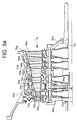
- Turbine T a for example, illustrated in Figure 3a, may be for use with 60Hz applications, whereas turbine T b , illustrated in Figure 3b, may be for use with 50Hz applications. Suffice it to say that the two turbines T a and T b are designed for different power outputs for the 60Hz and 50Hz applications.
- turbine T a includes an outer shell 40a forming the structural outer shell or housing of the turbine, an inner shell 42a and a rotor Ra.
- Rotor Ra mounts a plurality of bucket wheels 44a, as well as spacer wheels 46a between adjoining bucket wheels 44a, all bolted together between forward and aft shafts 48a and 50a, respectively, by a plurality of bolts 52a arranged about the longitudinal axis of the rotor Ra.
- the turbine T a includes a first stage, at least one intermediate stage (preferably two) and a last stage, each stage comprising a diaphragm mounting a plurality of circumferentially spaced partitions or nozzle vanes between inner and outer rings and a plurality of buckets mounted on the turbine wheels.
- a four-stage turbine is provided, with first-stage nozzles 54a, buckets 56a; second-stage nozzles 58a and buckets 60a; third-stage nozzles 62a and buckets 64a; and fourth-stage nozzles 66a and buckets 68a.
- the nozzles 54a, 58a, 62a and 66a form part of diaphragms mounting the partitions extending between the inner and outer diaphragm rings in the usual manner.
- the inner shell 42a carries shrouds 70a and 72a about the outer tips of buckets 56a and 60a of the first and second stages, respectively.
- Shrouds 74a and 76a are carried directly by the outer shell 40a about the tips of the third and fourth-stage buckets 64a and 68a.
- the nozzles, the shrouds and the outer surfaces of the bucket wheels define an annular flowpath through the turbine which receives the hot gases of combustion for expansion through the various stages, thereby imparting work to the buckets and rotor.
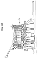
- the turbine T b illustrated in Figure 3b has like parts similarly arranged and designated by like reference numerals, followed by the letter "b."
- the turbine T a illustrated in Figure 3a is designed for a specified power output at a certain rotational speed and power grid frequency, e.g., 3600 rpm for 60Hz applications
- the turbine of Figure 3b is designed for a specified power output at a different rotational speed and power grid frequency, e.g., 3000 rpm for 50Hz applications.
- the turbines have a high degree of hardware commonality whereby the common hardware parts can be interchangeably used in either of the two turbines having the different power outputs at the different frequencies.
- the cross-sectional area of the annulus defining the flowpath through the first, second and third stages is identical through the two turbines.
- the flowpath inner radius is set to be common in the two turbines.
- the last-stage annulus can likewise be set for a given firing temperature, turbine pressure ratio and quantity of cooling air introduced, thus determining the bucket tip radius of the last stage.
- the bucket length is limited by the higher frequency machine, e.g., a 60Hz turbine.
- the height of the exit annulus of the final stage is increased to afford an increased exit area.
- the inner radius of the last-stage diaphragm and buckets remains the same and consequently, the radius of the last-stage partitions and buckets are enlarged at the outer radius of the flowpath to meet the increased mass flow and slower speed requirements of the 50Hz turbine as compared with the 60Hz turbine.
- the first-stage nozzles and buckets are restaggered to increase their throat areas while maintaining the annulus area constant as between the two turbines.
- the orientation of the buckets and partitions in the first stage of the 60Hz turbine is changed when a 50Hz turbine is undergoing fabrication.
- the profiles of the airfoils of the first stage are also changed to accommodate this increase in mass flow. It has been found, however, that the speed and mass flow changes as between the 60 and 50Hz turbines can be accommodated by a particular (and common) airfoil design in the second and third stages without substantial performance loss. Consequently, the second and third stages, including the partitions, buckets, wheels and shrouds, are sized and dimensioned identically to permit interchangeability of the second and third stages in either one of the two turbines of different power outputs and frequency applications.
- the intermediate stages of the turbine design can be modularized for installation in either one of the two machines of different power outputs at the different frequencies.
- the partitions and buckets of the second and third stages of the two machines are identical.
- the rotor wheels for all buckets e.g., the first, second, third and fourth-stage buckets, the spacers between the stages, the impeller plate, the aft and forward shafts, and seal plates constitute common hardware as between the 60Hz and 50Hz machines.
- the shrouds for the first, second and third-stage buckets, as well as the inner and outer shells are common between the 60 and 50Hz turbines.
- the rotors Ra and Rb are also common.
- the uniqueness of the 50 and 60Hz turbines is manifested primarily in the first and last stages. Particularly in the first stage, the throat area between the partitions for the 50Hz turbine is opened to accommodate the greater mass flow as compared with the 60Hz turbine. With respect to the last or fourth stage, the buckets and partitions are increased in radius at their tip ends to accommodate the increased mass flow for the 50Hz machine.
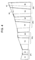
- the first, second, third and fourth stages ST1, ST2, ST3 and ST4 are illustrated with each having nozzles and buckets designated by the letter N and B, respectively, followed by a number indicating the turbine stage.
- the cross-sectional area of the annulus for both the 50Hz and 60Hz turbines is identical for the first, second and third stages and that the flowpath through the second and third stages is identical.
- the lower mass flow, higher speed 60Hz machine has an outer annulus wall 80, illustrated by the dashed line, while the larger mass flow, lower speed 50Hz machine has an outer wall 82.
- the increase in the radius of the nozzles N4 and buckets B4 of the fourth stage at their tips is thus indicated by the solid line 82 for the larger mass flow lower speed 50Hz machine.
Landscapes
- Engineering & Computer Science (AREA)
- Physics & Mathematics (AREA)
- Fluid Mechanics (AREA)
- Mechanical Engineering (AREA)
- General Engineering & Computer Science (AREA)
- Turbine Rotor Nozzle Sealing (AREA)
Applications Claiming Priority (2)
| Application Number | Priority Date | Filing Date | Title |
|---|---|---|---|
| US08/414,701 US5520512A (en) | 1995-03-31 | 1995-03-31 | Gas turbines having different frequency applications with hardware commonality |
| US414701 | 1995-03-31 |
Publications (2)
| Publication Number | Publication Date |
|---|---|
| EP0735239A1 true EP0735239A1 (fr) | 1996-10-02 |
| EP0735239B1 EP0735239B1 (fr) | 2005-10-26 |
Family
ID=23642580
Family Applications (1)
| Application Number | Title | Priority Date | Filing Date |
|---|---|---|---|
| EP96300493A Expired - Lifetime EP0735239B1 (fr) | 1995-03-31 | 1996-01-24 | Système de turbine à gaz et procédé de fabrication |
Country Status (4)
| Country | Link |
|---|---|
| US (1) | US5520512A (fr) |
| EP (1) | EP0735239B1 (fr) |
| JP (1) | JP3835849B2 (fr) |
| DE (1) | DE69635324T2 (fr) |
Families Citing this family (27)
| Publication number | Priority date | Publication date | Assignee | Title |
|---|---|---|---|---|
| US5839267A (en) * | 1995-03-31 | 1998-11-24 | General Electric Co. | Cycle for steam cooled gas turbines |
| JP3898785B2 (ja) * | 1996-09-24 | 2007-03-28 | 株式会社日立製作所 | 高低圧一体型蒸気タービン用動翼と高低圧一体型蒸気タービン及びコンバインド発電システム並びに複合発電プラント |
| EP1010857B1 (fr) | 1998-12-16 | 2003-06-04 | ALSTOM (Switzerland) Ltd | Turbine à vapeur modulaire avec aubage standard |
| US6393825B1 (en) * | 2000-01-25 | 2002-05-28 | General Electric Company | System for pressure modulation of turbine sidewall cavities |
| US6691519B2 (en) | 2000-02-18 | 2004-02-17 | Siemens Westinghouse Power Corporation | Adaptable modular gas turbine power plant |
| DE10221348B4 (de) * | 2002-05-08 | 2004-08-26 | Nordex Energy Gmbh | Verfahren zur Auslegung einer Windkraftanlage und danach ausgelegter Satz von Windkraftanlagen mit unterschiedlichen Nennleistungen |
| EP1918547B1 (fr) * | 2002-06-25 | 2017-05-03 | Mitsubishi Hitachi Power Systems, Ltd. | Procédé de fabrication des turbines à gaz |
| AU2009210402A1 (en) * | 2002-07-24 | 2009-09-10 | Timi 3 Systems, Inc. | Systems and methods for monitoring and enabling use of a medical instrument |
| DE102004036238A1 (de) | 2004-07-26 | 2006-02-16 | Alstom Technology Ltd | Verfahren zur Modifikation eines Turbokompressors |
| EP1790826A1 (fr) * | 2005-11-24 | 2007-05-30 | Siemens Aktiengesellschaft | Aube statorique pour une turbine d'une centrale thermique |
| US7681401B2 (en) * | 2006-08-24 | 2010-03-23 | General Electric Company | Methods and systems for operating a gas turbine |
| EP2122129B1 (fr) * | 2007-02-14 | 2018-04-11 | General Electric Technology GmbH | Centrale électrique et procédé de fonctionnement |
| JP5091256B2 (ja) * | 2007-02-14 | 2012-12-05 | アルストム テクノロジー リミテッド | 発電設備の作動方法 |
| DE102007007913A1 (de) * | 2007-02-14 | 2008-08-21 | Alstom Technology Ltd. | Verfahren zum Betrieb einer Kraftwerksanlage |
| JP5091255B2 (ja) * | 2007-02-14 | 2012-12-05 | アルストム テクノロジー リミテッド | 負荷を備える発電設備ならびにその作動方法 |
| US20090193783A1 (en) * | 2008-01-31 | 2009-08-06 | General Electric Company | Power generating turbine systems |
| DE112009000663B4 (de) | 2008-03-25 | 2022-11-03 | General Electric Technology Gmbh | Verfahren zum betrieb einer kraftwerksanlage |
| US9062554B2 (en) * | 2012-01-03 | 2015-06-23 | General Electric Company | Gas turbine nozzle with a flow groove |
| US10240526B2 (en) | 2012-01-31 | 2019-03-26 | United Technologies Corporation | Gas turbine engine with high speed low pressure turbine section |
| US20130192191A1 (en) | 2012-01-31 | 2013-08-01 | Frederick M. Schwarz | Gas turbine engine with high speed low pressure turbine section and bearing support features |
| US20130192263A1 (en) * | 2012-01-31 | 2013-08-01 | Gabriel L. Suciu | Gas turbine engine with high speed low pressure turbine section |
| US10287914B2 (en) | 2012-01-31 | 2019-05-14 | United Technologies Corporation | Gas turbine engine with high speed low pressure turbine section and bearing support features |
| US9845726B2 (en) | 2012-01-31 | 2017-12-19 | United Technologies Corporation | Gas turbine engine with high speed low pressure turbine section |
| US10125693B2 (en) | 2012-04-02 | 2018-11-13 | United Technologies Corporation | Geared turbofan engine with power density range |
| US20140130479A1 (en) * | 2012-11-14 | 2014-05-15 | United Technologies Corporation | Gas Turbine Engine With Mount for Low Pressure Turbine Section |
| CN104420887B (zh) * | 2013-08-30 | 2016-06-15 | 哈尔滨汽轮机厂有限责任公司 | 一种燃气轮机的透平机 |
| US11401835B2 (en) * | 2017-06-12 | 2022-08-02 | General Electric Company | Turbine center frame |
Citations (3)
| Publication number | Priority date | Publication date | Assignee | Title |
|---|---|---|---|---|
| CH85282A (de) * | 1919-01-20 | 1920-06-01 | Spiess Paul | Verfahren zur Herstellung mehrstufiger, axialer Freistrahl-Dampf- oder Gasturbinen verschiedener Leistungen in Gruppen. |
| FR1483743A (fr) * | 1965-12-02 | 1967-06-09 | Snecma | Turbomachine à compresseur contrarotatif |
| DE2408641A1 (de) * | 1974-02-21 | 1975-08-28 | Aeg Kanis Turbinen | Beschaufelung von stroemungsmaschinen |
Family Cites Families (1)
| Publication number | Priority date | Publication date | Assignee | Title |
|---|---|---|---|---|
| US5110256A (en) * | 1991-02-11 | 1992-05-05 | Westinghouse Electric Corp. | Methods and apparatus for attaching a flow guide to a steam turbine for retrofit of longer rotational blades |
-
1995
- 1995-03-31 US US08/414,701 patent/US5520512A/en not_active Expired - Lifetime
-
1996
- 1996-01-24 EP EP96300493A patent/EP0735239B1/fr not_active Expired - Lifetime
- 1996-01-24 DE DE69635324T patent/DE69635324T2/de not_active Expired - Lifetime
- 1996-04-01 JP JP07861096A patent/JP3835849B2/ja not_active Expired - Lifetime
Patent Citations (3)
| Publication number | Priority date | Publication date | Assignee | Title |
|---|---|---|---|---|
| CH85282A (de) * | 1919-01-20 | 1920-06-01 | Spiess Paul | Verfahren zur Herstellung mehrstufiger, axialer Freistrahl-Dampf- oder Gasturbinen verschiedener Leistungen in Gruppen. |
| FR1483743A (fr) * | 1965-12-02 | 1967-06-09 | Snecma | Turbomachine à compresseur contrarotatif |
| DE2408641A1 (de) * | 1974-02-21 | 1975-08-28 | Aeg Kanis Turbinen | Beschaufelung von stroemungsmaschinen |
Non-Patent Citations (1)
| Title |
|---|
| D.KALDERON: "Design of large steam turbines.", GEC TURBINE GENERATORS LTD., RUGBY, ENGLAND, XP002007571 * |
Also Published As
| Publication number | Publication date |
|---|---|
| DE69635324D1 (de) | 2005-12-01 |
| DE69635324T2 (de) | 2006-07-13 |
| JPH094465A (ja) | 1997-01-07 |
| JP3835849B2 (ja) | 2006-10-18 |
| US5520512A (en) | 1996-05-28 |
| EP0735239B1 (fr) | 2005-10-26 |
Similar Documents
| Publication | Publication Date | Title |
|---|---|---|
| US5520512A (en) | Gas turbines having different frequency applications with hardware commonality | |
| US4889470A (en) | Compressor diaphragm assembly | |
| AU603136B2 (en) | Axial flow turbine | |
| EP1331360B1 (fr) | Disposition des aubes statoriques et rotoriques au niveau de l'échappement d'une turbine | |
| EP1835147B1 (fr) | Groupe de soufflante et moteur à turbine à gaz associé | |
| US6905303B2 (en) | Methods and apparatus for assembling gas turbine engines | |
| JP4644465B2 (ja) | 分割流式タービンノズル | |
| US7670109B2 (en) | Turbine | |
| EP0384166B1 (fr) | Construction de diaphragme de compresseur | |
| US4719747A (en) | Apparatus for optimizing the blade and sealing slots of a compressor of a gas turbine | |
| EP0578639B1 (fr) | Carter de turbine | |
| EP1033476B1 (fr) | Circuit d'échange thermique pour un rotor de turbine | |
| EP2589751B1 (fr) | Chemin d'écoulement de dernier étage de turbine | |
| EP2166194A2 (fr) | Virole de turbine à double étage | |
| EP0735254B1 (fr) | Cycle pour turbines à gaz refroidi par vapeur | |
| GB2043794A (en) | Turbine shrouding | |
| US12071889B2 (en) | Counter-rotating turbine | |
| EP3812560A1 (fr) | Arbre de turbine | |
| US20050120719A1 (en) | Internally insulated turbine assembly | |
| EP3812563A1 (fr) | Moteur à turbine à gaz | |
| Sugimoto et al. | Development of a 20MW-class high-efficiency gas turbine L20A | |
| US20240271542A1 (en) | Low-pressure turbine | |
| US20080127630A1 (en) | Turbine for application to pulse detonation combustion system and engine containing the turbine | |
| KR100470771B1 (ko) | 복합사이클식가스터빈의운전방법 | |
| SAUNDERS | Advanced component technologies for energy-efficient turbofan engines |
Legal Events
| Date | Code | Title | Description |
|---|---|---|---|
| PUAI | Public reference made under article 153(3) epc to a published international application that has entered the european phase |
Free format text: ORIGINAL CODE: 0009012 |
|
| AK | Designated contracting states |
Kind code of ref document: A1 Designated state(s): CH DE FR GB IT LI |
|
| 17P | Request for examination filed |
Effective date: 19970402 |
|
| 17Q | First examination report despatched |
Effective date: 19990825 |
|
| APBN | Date of receipt of notice of appeal recorded |
Free format text: ORIGINAL CODE: EPIDOSNNOA2E |
|
| APBR | Date of receipt of statement of grounds of appeal recorded |
Free format text: ORIGINAL CODE: EPIDOSNNOA3E |
|
| APBV | Interlocutory revision of appeal recorded |
Free format text: ORIGINAL CODE: EPIDOSNIRAPE |
|
| GRAP | Despatch of communication of intention to grant a patent |
Free format text: ORIGINAL CODE: EPIDOSNIGR1 |
|
| RTI1 | Title (correction) |
Free format text: GAS TURBINE SYSTEM AND METHOD OF MANUFACTURING |
|
| GRAS | Grant fee paid |
Free format text: ORIGINAL CODE: EPIDOSNIGR3 |
|
| GRAA | (expected) grant |
Free format text: ORIGINAL CODE: 0009210 |
|
| AK | Designated contracting states |
Kind code of ref document: B1 Designated state(s): CH DE FR GB IT LI |
|
| REG | Reference to a national code |
Ref country code: GB Ref legal event code: FG4D |
|
| REG | Reference to a national code |
Ref country code: CH Ref legal event code: EP |
|
| REG | Reference to a national code |
Ref country code: CH Ref legal event code: NV Representative=s name: SERVOPATENT GMBH |
|
| REF | Corresponds to: |
Ref document number: 69635324 Country of ref document: DE Date of ref document: 20051201 Kind code of ref document: P |
|
| ET | Fr: translation filed | ||
| PLBE | No opposition filed within time limit |
Free format text: ORIGINAL CODE: 0009261 |
|
| STAA | Information on the status of an ep patent application or granted ep patent |
Free format text: STATUS: NO OPPOSITION FILED WITHIN TIME LIMIT |
|
| 26N | No opposition filed |
Effective date: 20060727 |
|
| REG | Reference to a national code |
Ref country code: CH Ref legal event code: PFA Owner name: GENERAL ELECTRIC COMPANY Free format text: GENERAL ELECTRIC COMPANY#1 RIVER ROAD#SCHENECTADY, NY 12345 (US) -TRANSFER TO- GENERAL ELECTRIC COMPANY#1 RIVER ROAD#SCHENECTADY, NY 12345 (US) |
|
| REG | Reference to a national code |
Ref country code: FR Ref legal event code: PLFP Year of fee payment: 20 |
|
| PGFP | Annual fee paid to national office [announced via postgrant information from national office to epo] |
Ref country code: CH Payment date: 20150126 Year of fee payment: 20 Ref country code: DE Payment date: 20150128 Year of fee payment: 20 Ref country code: IT Payment date: 20150126 Year of fee payment: 20 |
|
| PGFP | Annual fee paid to national office [announced via postgrant information from national office to epo] |
Ref country code: FR Payment date: 20150119 Year of fee payment: 20 Ref country code: GB Payment date: 20150127 Year of fee payment: 20 |
|
| REG | Reference to a national code |
Ref country code: DE Ref legal event code: R071 Ref document number: 69635324 Country of ref document: DE |
|
| REG | Reference to a national code |
Ref country code: CH Ref legal event code: PL |
|
| REG | Reference to a national code |
Ref country code: GB Ref legal event code: PE20 Expiry date: 20160123 |
|
| PG25 | Lapsed in a contracting state [announced via postgrant information from national office to epo] |
Ref country code: GB Free format text: LAPSE BECAUSE OF EXPIRATION OF PROTECTION Effective date: 20160123 |