EP0734579B1 - Contact block having convertible normally open or normally closed electrical contacts - Google Patents
Contact block having convertible normally open or normally closed electrical contacts Download PDFInfo
- Publication number
- EP0734579B1 EP0734579B1 EP95935726A EP95935726A EP0734579B1 EP 0734579 B1 EP0734579 B1 EP 0734579B1 EP 95935726 A EP95935726 A EP 95935726A EP 95935726 A EP95935726 A EP 95935726A EP 0734579 B1 EP0734579 B1 EP 0734579B1
- Authority
- EP
- European Patent Office
- Prior art keywords
- actuator
- contact
- pair
- housing
- control device
- Prior art date
- Legal status (The legal status is an assumption and is not a legal conclusion. Google has not performed a legal analysis and makes no representation as to the accuracy of the status listed.)
- Expired - Lifetime
Links
Images


Classifications
-
- H—ELECTRICITY
- H01—ELECTRIC ELEMENTS
- H01H—ELECTRIC SWITCHES; RELAYS; SELECTORS; EMERGENCY PROTECTIVE DEVICES
- H01H1/00—Contacts
- H01H1/12—Contacts characterised by the manner in which co-operating contacts engage
- H01H1/14—Contacts characterised by the manner in which co-operating contacts engage by abutting
- H01H1/20—Bridging contacts
- H01H1/2008—Facilitate mounting or replacing contact bridge and pressure spring on carrier
-
- H—ELECTRICITY
- H01—ELECTRIC ELEMENTS
- H01H—ELECTRIC SWITCHES; RELAYS; SELECTORS; EMERGENCY PROTECTIVE DEVICES
- H01H11/00—Apparatus or processes specially adapted for the manufacture of electric switches
- H01H11/0006—Apparatus or processes specially adapted for the manufacture of electric switches for converting electric switches
- H01H11/0012—Apparatus or processes specially adapted for the manufacture of electric switches for converting electric switches for converting normally open to normally closed switches and vice versa
Definitions
- the invention is related to electrical contacts for making or breaking an electrical circuit and more particularly to a contact block having a stationary set of contacts which can be selectively converted to either normally open or normally closed contacts.
- the contact block has either a normally closed or a normally open contact to control the current flowing in an electrical circuit.
- the contact block can typically be used in a limit switch, with a push button operator to form a push button switch, or in any other situation wherein an object can physically move an actuator thereby causing the normally closed or normally open contacts to change state.
- the contact block generally comprises a first pair of stationary contacts and a pair of movable contacts attached to the actuator. The actuator is biased such that the movable contacts are either in the closed or open position with relation to the first stationary contacts.
- auxiliary contact In other types of circuit control devices employing a stationary contact and a movable contact operated by an actuator to make or break the circuit it is sometimes required that an additional control circuit be operated by the same actuator. For these applications it is common to provide an auxiliary contact.
- the auxiliary contact is generally contained within an enclosure and includes a pair of stationary contacts, a pair of movable contacts mounted on an actuator, a biasing spring, and a pair of wire terminal connectors.
- the auxiliary contact enclosure is mounted on the outside of the circuit control device enclosure in a location that permits access to the primary contactor actuator such that the auxiliary contact can be operated simultaneously with the primary contactor.
- the trip mechanism of the primary contactor must be designed to overcome not only the biasing spring and latching friction of the primary contacts but also the biasing spring of the auxiliary contact.
- This increases the cost of the circuit control device regardless of whether or not an auxiliary contact is employed.
- the auxiliary contacts like the contact blocks, are available in either a normally open or a normally closed function and must be purchased separately as an accessory for the control device. This means that an inventory of both normally open and normally closed auxiliary contacts is required to insure that the desired auxiliary contact is available when required. It would therefore be desirable to have a circuit control device with an internal auxiliary contact that can be easily converted from a normally open to a normally closed contact and which does not have an additional biasing spring for the trip mechanism to overcome.
- US-A-2,649,514 discloses auxiliary electric switch contact units, for use in connection with magnetic motor-starters, limit switches and door switches, provided with a plurality of contacts arrangeable into various combinations of normally open or normally closed relatively moveable companion contacts.
- the present invention provides a convertible contact which can be selectively and easily changed between a normally open function and a normally closed function by the user.
- the convertible contact of the present invention can be used with any electrical control device capable of having two spaced apart movable contacts located on a common movable member.
- the convertible contact of the present invention can be used as the primary contact of a contact block or an auxiliary contact of other circuit control devices.
- a contact block as hereinafter defined in claim 1 and according to a further aspect of the invention there is provided an electrical control device as hereinafter defined in claim 17.
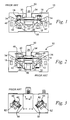
- Figure 1 is an interior view of a typical normally closed contact block of the prior art.
- Figure 2 is an interior view of a typical normally open contact block of the prior art.
- Figure 3 is an exterior view of a typical contact block of the prior art.
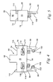
- Figure 4 is a front view of a convertible auxiliary contact constructed in accordance with the present invention.
- Figure 5 is an end view of a convertible auxiliary contact constructed in accordance with the present invention.
- Figure 6 is an interior view of a contact block constructed in accordance with the present invention.
- Figure 7 is an exterior view of a contact block constructed in accordance with the present invention.
- Figure 8 is exterior view of a contact block constructed in accordance with the present invention with a convertible stationary contact installed in the normally open position.
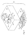
- Figure 9 is an exploded view of a circuit control device having a conventional dedicated contact and a convertible auxiliary contact in accordance with the present invention operated by a common actuator.
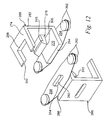
- Figure 10 is an isometric view of an alternate construction for a contact carrier/acturator for supporting two sets of movable contacts.
- Figure 11 is an end view of the assembled contact carrier/actuator of Figure 10.
- Figure 12 is an exploded view of the contact carrier/actuator of figure 10.
- FIG. 1 illustrates the inside of a contact block of the prior art generally and is indicated by reference numeral 10.
- the contact block 10 includes a housing 14 which defines a generally hollow interior for supporting and enclosing at least one pair of stationary contacts 18, at least one pair of bussing members 22, a portion of an actuator 26, at least one flexible member 30 supported by the actuator 26, at least one pair of movable contacts 34, and an actuator biasing spring 38.
- Each pair of stationary contacts 18 is positioned within the housing 14 such that one stationary contact 18 is spaced apart from the other stationary contact 18 a preselected distance and both lie in a common plane.
- Each stationary contact 18 is connected to one end of an associated bussing member 22.
- a terminal end 42 of each bussing member 18 extends outboard of the housing 14 through a passage 44 in the housing 14.
- Each flexible member 30 is generally rectangular in shape and is supported at its approximate midpoint by the actuator 26 such that it has two opposing ends 46 being spaced apart a preselected distance.
- Each flexible member 30 is positioned generally perpendicular to the longitudinal axis of the actuator 26 and parallel to the plane of the pairs of stationary contacts 18.
- At least one movable contact 34 is attached at each of the opposing ends 46 of the flexible member 30.
- the actuator 26 has a distal end 50 which extends outboard of the housing 14 through a passage 54 in the housing 14.
- the actuator 26 is slidably movable along its longitudinal axis between a first position and a second position.
- the biasing spring 38 is located between a portion of the housing 14 and the actuator 26 urging the actuator 26 to maintain its first position.
- An external force exerted on the distal end 50 of the actuator 26 is required to move the actuator 26 to its second position.
- the stationary contacts 18 are positioned within the housing 14 such that when the actuator 26 is biased by the spring 38 to its first position, the movable contacts 34 are in contact with the stationary contacts 18 thereby providing a contact block having normally closed contacts.
- the stationary contacts 18 are positioned within the housing 14 such that when the actuator 26 is biased by the spring 38 to its first position, the movable contacts 34 are spaced apart from the stationary contacts 18 thereby providing a contact block having normally open contacts.
- Figure 3 illustrates an assembled prior art contact block with a terminal clamp 58 and a screw 62 fitted to each of the extending terminal ends 42.
- FIGS 4 and 5 illustrate a convertible stationary contact module 66 constructed in accordance with the present invention.
- the contact module 66 includes a housing 70 which is generally rectangular in shape.
- the housing 70 has a generally flat top surface 74, a front surface 78 and a back surface 82.
- the front and back surfaces, 78 and 82 respectively, are generally parallel to one another and spaced apart by the top surface 74.
- a generally rectangular handle 86 extends upward from a middle portion of the top surface 74.
- Two generally flat bussing conductors 90 are supported by and partially enclosed by the contact module housing 70. A portion of each bussing conductor 90 extends outwardly from and generally perpendicular to a bottom surface 94 of the housing 70 to a distal end 98.
- the bussing conductors 90 pass through the housing 70 at a point between the longitudinal center line of the contact module 66 and the back surface 82 of the housing 70.
- the distal end 98 of each bussing conductor 90 has a contact pad 102.
- a stationary contact 106 is fixed to the side of the contact pad 102 facing toward the front surface 78 of the housing 70.
- a contact indicator 110 extends outwardly from and generally perpendicular to the top surface 74 at a point between the longitudinal center line of the contact module 66 and the back surface 82.
- the contact indicators 110 indicate the position of the bussing conductors 90 and the stationary contacts 106.
- Two passages 114 each communicating between the front and back surfaces, 78 and 82 respectively, and each located adjacent one of the bussing conductors 90, provide access to a wire terminal screw 118 for external wiring to the contact module 66.
- Figures 6 illustrates the interior of a contact block 122 constructed in accordance with the present invention.
- the contact block 122 of the present invention has a housing 126 which defines a generally hollow interior for supporting and enclosing an actuator 130, at least one flexible member 134 supported by the actuator 130, two pairs of movable contacts 138 and an actuator biasing spring 142.
- a generally rectangular contact cavity 146 is defined on each side of the actuator 130. The contact cavities 146 receive the stationary contacts 106 of the contact module 66 shown in Figures 4 and 5.
- Each flexible member 134 is generally rectangular in shape and is supported at its approximate midpoint by the actuator 130 such that it has two distal ends 150 being spaced apart a preselected distance. Each flexible member 134 lies in a plane generally perpendicularly to the longitudinal axis of the actuator 130. At least one movable contact 138 is attached to each side of the flexible member 134 at each of the distal ends 150.
- the actuator 130 has a distal end 154 which extended outboard of the housing 126 through a passage 158 in the housing 126.
- the actuator 130 is slidably movable along its longitudinal axis between a first position and a second position.
- the biasing spring 142 is located between a portion of the housing 126 and the actuator 130, thereby urging the actuator 130 to maintain its first position.
- An external force exerted on end 154 or the actuator 130 is required to move the actuator 130 to its second position.
- Figure 7 illustrates an assembled contact block 122 of the present invention.
- the housing 126 includes indicia indicating normally closed (NC) 162 and normally open (NO) 166.
- NC normally closed
- NO normally open
- Two generally rectangular apertures 170 generally adjacent to the NC indicia 162 provide access to the two contact cavities 146 at a location coinciding with the location of the movable contacts 138 when the actuator 130 is in the first position.
- Two generally rectangular apertures 174 generally adjacent to the NO indicia 166 provide access to the two contact cavities 146 at a location coinciding with the location of the movable contacts 138 when the actuator 130 is in the second position.
- the stationary contacts 106 and their associated bussing conductors 90 are received in apertures 170 when a normally closed contact block is desired and in apertures 174 when a normally open contact block is desired.
- An aperture 178 is provided for receiving a contact module mounting screw 178.
- Figure 8 illustrates a contact block 122 of the present invention with a contact module 66 of the present invention installed.
- the contact module 66 is in the normally closed position as indicated by the contact indicator 110 adjacent to the NC indicia 162.
- the contact module is attached to the contact block housing 126 by the mounting screw 178.
- the contact block is easily changed from normally closed to normally open by removing the mounting screw 178, removing the contact module 66 from the contact block 122, rotating the contact module 66 180° and reinstalling the contact module 66 on the contact block 122.
- Figure 9 illustrates a circuit control device generally indicated by reference numeral 182 having a pair of dedicated nonconvertible stationary contacts 186 supported by a base 190, a first pair of movable contacts 194 supported by a first flexible member 198 which is attached to an actuator 202, two pair of second movable contacts 206 supported by a second flexible member 210 which is also attached to the actuator 202 and a pair of contact cavities 214 defined by the base 190.
- the actuator 202 is biased to a first position by a spring 218 and slidably movable to a second position by a force exerted on an end 222 of the actuator 202.
- the base 190 and its associated components are enclosed within a housing 226.
- the housing 226 defines a pair of terminal apertures 230 for receiving the terminal ends 234 of the dedicated stationary contacts 186, a first pair of access apertures 238 and a second pair of access apertures 242 which provide access to the contact cavities 214.
- the first pair of access apertures 238 are associated with the second pairs of movable contacts 206 when the actuator 202 is in the first position and the second pair of access apertures 242 are associated with the second pair of movable contacts 206 when the actuator 202 is in the second position.
- the housing 226 also includes NC indicia 246 adjacent the first pair of access apertures 238 and NO indicia 250 adjacent the second pair of access apertures 242.
- the pairs of access apertures 238 and 242 receive the bussing conductors 98 and stationary contacts 106 of the convertible contact module 66, thereby providing the circuit control device 182 with a convertible auxiliary contact which is easily selectable between a normally closed contact and a normally open contact.
- a contact carrier/actuator assembly generally indicated as reference numeral 254 and illustrated in Figures 10, 11 and 12 provides a simple easily assembled method of supporting two flexible members 258 each of which has two movable contacts 262 attached to opposing sides of each of its opposing ends.
- the contact carrier/actuator assembly 254 consists of two identical opposing halves 266 which snap together and thereby captivate one flexible member 258 at each end of the assembly 254.
- Each half 266 has a generally E-shaped cross-section wherein a first outside leg 270, a second outside leg 274 and a center leg 278 each extending outwardly from and generally perpendicular to a base leg 282.
- the first outside legs 270 is shorter in length than the second outside leg 274 by an amount approximately equal to the thickness of the base leg 282.
- the center leg 278 is slightly shorter than the first and second outside legs, 270 and 274 respectively, and is not centered between the first and second outside legs, 270 and 274 respectively.
- the first outside leg 270 has a generally flat outside surface 286 from which a generally rectangular rib 290 extends outwardly and perpendicularly.
- the rib 290 is located approximately at the middle of the first outside leg 270 and runs generally parallel to a distal end 294 of the first outside leg 270.
- the outside second leg 274 defines a generally square slot 298 which extends inward from a distal end 302 of the second outside leg 274. The slot 298 is dimensioned to slidingly receive the rib 290 of said first outside leg 270.
- the center leg 278 includes a generally wedge-shaped distal end 306 which defines a hook 310.
- the center leg 278 is positioned such that when the two halves 266 are assembled together, the rib 290 of one half 266 is slidably received within the slot 298 of the opposing half 266 and the hooks 310 of the opposing center legs 278 interlock, thereby holding the contact carrier /actuator assembly 254 together.
- the flexible members 258 each have a slot 314 which is dimensioned to closely receive the rib 290 on the cooperating first outside leg 270.
- one flexible member 258 with its attached movable contacts 262 is placed on the generally flat outside surface 286 of the first outside leg 270 of each of the opposing halves 266 such that the rib 290 is received through the slot 314.
- the two opposing halves 266 are then aligned such that the ribs 290 of each first outside leg 270 are slidably received within the slots 298 of the second outside leg 274 of the opposing half 266.
- the hooks 310 of both center legs 278 become latched together.
- the flexible members 258 are capitivated between the generally flat surfaces 286 of the first outside legs 270 and the second outside legs 274 such that the ribs 290 prevent them from sliding out. Because the contact carrier/actuator assembly 254 is symmetrical, no special positioning is required during assembly.
Landscapes
- Engineering & Computer Science (AREA)
- Manufacturing & Machinery (AREA)
- Push-Button Switches (AREA)
- Coupling Device And Connection With Printed Circuit (AREA)
Description
Claims (35)
- A contact block (122) having at least.one set of electrical contacts (138) convertible between a normally open and normally closed state comprising:a housing (126) defining a generally hollow interior;an actuator (130) partially received within said housing (126) and being slidably movable between a first position and a second position;means (142) for biasing said actuator (130) to said first position;at least one pair of contact cavities (146) being defined by said housing (126) and being positioned immediately adjacent to and on opposite sides of said actuator (130);at least one pair of movable contacts (138), said movable contacts (138) being attached to said actuator (130) such that said movable contacts (138) are movable between a first position and a second position within said contact cavities (146);means (134) for attaching said movable contacts (138) to said actuator (130); characterised byat least two pair of access apertures (170, 174) providing access to said contact cavities (146) such that one pair of said access apertures (170) generally coincides with said first position of said movable contacts (138) and the other pair of said access apertures (174) generally coincides with said second position of said movable contacts (138); anda stationary contact module (66) having at least one pair of stationary contacts (106) which can be received through either of said pairs of access apertures (170, 174) for being selectively engaged with said movable contacts (138) in one of said first or second positions.
- A contact block (122) as claimed in claim 1 characterised in that said actuator (130) has a distal end (154) which extends outboard of said housing (126) through a passage (158).
- A contact block (122) as claimed in claim 2 characterised in that said actuator (130) is selectively movable from said first position to said second position in response to an external force exerted on said distal end (154) of said actuator (130).
- A contact block (122) as claimed in any preceding claim characterised in that said biasing means is a spring (142) positioned between a portion of said housing (126) and said actuator (130).
- A contact block (122) as claimed in any preceding claim characterised in that said actuator (130) is made from an electrically nonconductive material.
- A contact block as claimed in claim 5 characterised in that said means for attaching said movable contacts (138) to said actuator (130) is a flexible member (134), said flexible member (134) being generally flat and made from an electrically conductive material.
- A contact block (122) as claimed in claim 6 characterised in that said flexible member (134) is rigidly supported at its approximate midpoint by said actuator (130) such that flexible member (134) is generally perpendicular to said actuator (130), said flexible member (134) having two opposing ends (150) extending away from said actuator (130).
- A contact block (122) as claimed in claim 7 characterised in that one said movable contact (138) is attached to each of the opposing sides of said flexible member (134) at each of said opposing ends (150).
- A contact block (122) as claimed in any preceding claim characterised in that said housing (126) further includes an NC indicia (162) adjacent one said pair of access apertures (170) indicating a normally closed function and an NO indicia (166) adjacent the other said pair of access apertures (174) indicating a normally open function.
- A contact block (122) as claimed in any preceding claim characterised in that said stationary contact module (66) includes a housing (70) being generally rectangular in shape such that it is defined by a top surface (74) and a bottom surface (94) being generally parallel to and spaced apart from one another, and a front surface (78) and a back surface (82) being generally parallel to the spaced apart from one another, said front and back surfaces (78, 82) being intermediate said top and bottom surface (74, 94).
- A contact block (122) as claimed in claim 10 characterised in that said stationary contact module (66) further includes at least one pair of bussing conductors (90), said bussing conductors (90) being supported by and partially enclosed by said housing (70), a portion of each said bussing conductor (90) extending outwardly from and generally perpendicularly to said bottom surface (94) to a distal end (98), said bussing conductors (90) passing through said housing (70) at a point between a longitudinal centre line of said stationary contact module (66) and said back surface (82) of said housing (70).
- A contact block (122) as claimed in claim 11 characterised in that said distal end (98) of each said bussing conductor (90) further includes a contact pad (102) on which said stationary contacts (106) are fixedly mounted such that said stationary contacts (106) face said front surface (78).
- A contact block (122) as claimed in claim 10, 11 or 12 characterised in that said stationary contact module (66) further includes a pair of contact indicators (110), each extending outwardly from and generally perpendicularly to said top surface (74) at a point between said longitudinal centre line of said contact module (66) and said back surface (82) such that the position of said stationary contacts (106) is indicated by said contact indicators (110).
- A contact block (122) as claimed in claim 13 characterised in that said contact indicators (110) align with one of said NC indicia (162) or said NO indicia (166) depending on which pair of said access apertures (170, 174) said bussing conductors (90) pass through.
- A contact block (122) as claimed in claim 12, 13 or 14 characterised in that said contact module housing (70) defines two passages (114) communicating between said front and back surfaces (78, 82), each said passage (114) being adjacent one of said bussing conductors (90) such that access is provided to a wire terminal screw (118) associated with said adjacent bussing conductor (90).
- A contact block (122) as claimed in any preceding claim characterised in that said stationary contact module (66) is attached to said contact block housing (126) by a mounting screw (178).
- An electrical control device (182) having a set of auxiliary electrical contacts (206) convertible between a normally open and normally closed state, said control device (182) comprising:a housing (226) having a generally hollow interior and defining a pair of terminal apertures (230), a first pair of access apertures (238) and a second pair of access apertures (242), each of said apertures (238, 242) providing access to said generally hollow interior;a base (190) enclosed by said housing (226);an actuator (202) being supported by said base (190) such that said actuator (202) is slidably movable between a first position and a second position;means (218) for biasing said actuator (202) to said first position;a pair of stationary contacts (186) supported by said base (190);a first pair of movable contacts (194) being attached to said actuator (202) such that said first movable contacts (194) are movable between a first position and a second position relative to said pair of stationary contacts (186);means (198) for attaching said first pair of movable contacts (194) to said actuator (202); characterised in that at least one pair of contact cavities (214) being defined by said base (190), each said contact cavity (214) being immediately adjacent said actuator (202) such that said pair of contact cavities (214) is separated by said actuator (202), said base (190) being positioned within said housing (226) such that said access apertures (238, 242) provide an external access to said contact cavities (214);two second pairs of movable contacts (206), said movable contacts (206) being attached to said actuator (202) such that said second movable contacts (206) are movable between a first position and a second position within said contact cavities (214);means (202) for attaching said second pairs of movable contacts (206) to said actuator (202); anda stationary contact module (66) having at least one pair of stationary contacts (106) which can be received through either said first or second pairs of access apertures (238, 242) for being selectively engaged by one of said second pairs of movable contacts (206) in one of said first or second positions.
- An electrical control device (182) as claimed in claim 17 characterised in that said actuator (202) has a distal end (222).
- An electrical control device (182) as claimed in claim 18 wherein said actuator (202) is selectively movable from said first position to said second position in response to a force exerted on said distal end (222).
- An electrical control device (182) as claimed in claim 17, 18, or 19 characterised in that said biasing means is a spring (218) positioned between a portion of said base (190) and said actuator (202).
- An electrical control device (182) as claimed in claim 17, 18, 19 or 20 characterised in that said actuator (202) is made from an electrically nonconductive material.
- An electrical control device (182) as claimed in claim 21 characterised in that said means for attaching said first pair of movable contacts (19a) to said actuator (202) is a flexible member (198), said flexible member (198) being generally flat and made from an electrically conductive material.
- An electrical control device (182) as claimed in claim 22 characterised in that said flexible member (198) is rigidly supported at its approximate midpoint by said actuator (202) such that said flexible member (198) is generally perpendicular to said actuator (202), said flexible member (198) having two opposing ends extending away from said actuator (202).
- An electrical control device (182) as claimed in claim 23 characterised in that said movable contact (194) is attached to each said opposing end of said flexible member (198) such that said first movable contacts (194) face said stationary contacts (186).
- An electrical control device (182) as claimed in any one of claims 17 to 24 inclusive characterised in that said means for attaching said second pairs of movable contacts (206) to said actuator (202) is a flexible member (210),said flexible member (210) being generally flat and made from an electrically conductive material.
- An electrical control device (182) as claimed in claim 25 characterised in that said flexible member (210) is rigidly supported at its approximate midpoint by said actuator (202) such that said flexible member (210) is generally perpendicular to said actuator (202), said flexible member (210) having two opposing ends extending away from said actuator (202).
- An electrical control device (182) as claimed in claim 26 characterised in that one said movable contact (206) is attached to each side of said flexible member (210) at each of said opposing ends.
- An electrical control device (182) as claimed in any one of claims 17 to 27 inclusive characterised in that electrical control device housing (226) further includes an NC indicia (246) adjacent one said pair of access apertures (238) indicating a normally closed function and an NO indicia (250) adjacent the other said pair of access apertures (242) indicating a normally open function.
- An electrical control device (182) as claimed in any one of claims 17 to 28 inclusive characterised in that said stationary contact module (66) includes a housing (70) being generally rectangular in shape such that is defined by a top surface (74) and a bottom surface (94) being generally parallel to and spaced apart from one another, and a front surface (78) and a back surface (82) being generally parallel to and spaced apart from one another, said front and back surface (78, 82) being intermediate said top and bottom surfaces (74, 94).
- An electrical control device (182) as claimed in claim 29 characterised in that said stationary contact module (66) further includes at least one pair of bussing conductors (90), said bussing conductors (90) being supported by and partially enclosed by said housing (70), a portion of each said bussing conductor (90) extending outwardly from and generally perpendicularly to said bottom surface (94) to a distal end (98), said bussing conductors (90) passing through said housing (70) at a point between a longitudinal centre line of said stationary contact module (66) and said back surface (82) of said housing (70).
- An electrical control device (182) as claimed in claim 30 characterised in that said distal end (98) of each said bussing conductor (90) further includes a contact pad (102) on which said stationary contacts (106) are fixedly mounted such that said stationary contacts (106) face said front surface (78) of said stationary contact module (66).
- An electrical control device (182) as claimed in claim 29, 30 or 31 characterised in that said stationary contact module (66) further includes a pair of contact indicators (110), each extending outwardly from and generally perpendicularly to said top surface (74) at a point between said longitudinal centre line of said contact module (66) and said back surface (82) such that the position of said stationary contacts (106) is indicated by said contact indicators (110).
- An electrical control device (182) as claimed in claim 32 characterised in that said contact indicators (110) of said stationary contact module (66) align with one of said NC indicia (246) or said NO indicia (250) depending on which pair of said access apertures (238, 242) said bussing conductors (90) pass through.
- An electrical control device (182) as claimed in claim 30, 31, 32 or 33 characterised in that said stationary contact module housing (70) defines two passages (114) communicating between said front and back surfaces (78, 82), each said passage (114) being adjacent one of said bussing conductors (90) such that access is provided to a wire terminal screw (118) associated with said adjacent bussing conductor (90).
- An electrical control device (182) as claimed in any one of claims 17 to 34 inclusive characterised in that said stationary contact module (66) is attached to said electrical control device housing (226) by a mounting screw (178).
Applications Claiming Priority (3)
| Application Number | Priority Date | Filing Date | Title |
|---|---|---|---|
| US08/322,631 US5532441A (en) | 1994-10-13 | 1994-10-13 | Contact block having convertible normally open or normally closed electrical contact |
| US322631 | 1994-10-13 | ||
| PCT/US1995/012833 WO1996012290A1 (en) | 1994-10-13 | 1995-10-13 | Contact block having convertible normally open or normally closed electrical contacts |
Publications (2)
| Publication Number | Publication Date |
|---|---|
| EP0734579A1 EP0734579A1 (en) | 1996-10-02 |
| EP0734579B1 true EP0734579B1 (en) | 1999-06-02 |
Family
ID=23255719
Family Applications (1)
| Application Number | Title | Priority Date | Filing Date |
|---|---|---|---|
| EP95935726A Expired - Lifetime EP0734579B1 (en) | 1994-10-13 | 1995-10-13 | Contact block having convertible normally open or normally closed electrical contacts |
Country Status (6)
| Country | Link |
|---|---|
| US (1) | US5532441A (en) |
| EP (1) | EP0734579B1 (en) |
| AU (1) | AU698832B2 (en) |
| DE (1) | DE69510030T2 (en) |
| ES (1) | ES2135773T3 (en) |
| WO (1) | WO1996012290A1 (en) |
Families Citing this family (2)
| Publication number | Priority date | Publication date | Assignee | Title |
|---|---|---|---|---|
| US5347519A (en) * | 1991-12-03 | 1994-09-13 | Crosspoint Solutions Inc. | Preprogramming testing in a field programmable gate array |
| FR2821980B1 (en) * | 2001-03-09 | 2003-04-25 | Schneider Electric Ind Sa | MULTIPOLAR CONTACT BLOCK |
Family Cites Families (17)
| Publication number | Priority date | Publication date | Assignee | Title |
|---|---|---|---|---|
| US2649514A (en) * | 1949-08-17 | 1953-08-18 | Fed Electric Prod Co | Electric switch |
| US2532305A (en) * | 1949-08-17 | 1950-12-05 | Cutler Hammer Inc | Electric switch |
| US2562420A (en) * | 1949-10-21 | 1951-07-31 | Furnas Electric Co | Interchangeable electric switch |
| US2885516A (en) * | 1956-08-13 | 1959-05-05 | Square D Co | Contact holder |
| US3161751A (en) * | 1962-05-17 | 1964-12-15 | Gen Electric | Reversible electrical contact structure |
| US3328552A (en) * | 1966-04-04 | 1967-06-27 | Square D Co | Electric switching device |
| US3436497A (en) * | 1967-08-31 | 1969-04-01 | Cutler Hammer Inc | Electrical switch having a lost motion operator assembly |
| US3641287A (en) * | 1970-04-16 | 1972-02-08 | Gen Electric | Switching device for electromagnetic motor starters |
| US4052582A (en) * | 1976-03-08 | 1977-10-04 | Westinghouse Electric Corporation | Rotary selector switch |
| US4087770A (en) * | 1976-06-29 | 1978-05-02 | Allen-Bradley Company | Industrial relay |
| US4184134A (en) * | 1978-08-14 | 1980-01-15 | Clark Control, Inc. | Electrical switching apparatus having convertible contact structure |
| DE2848105A1 (en) * | 1978-11-06 | 1980-05-14 | Metzenauer & Jung Gmbh | SWITCH ARRANGEMENT WITH CHANGEABLE SWITCH CONTACTS TO OPEN OR OPEN |
| US4355216A (en) * | 1981-01-02 | 1982-10-19 | Gte Products Corporation | Electric switch |
| US4774484A (en) * | 1985-04-09 | 1988-09-27 | Square D Company | Auxiliary electrical contact for electromagnetic contactor |
| DE3579597D1 (en) * | 1985-10-24 | 1990-10-11 | Square D Deutschland | SWITCHGEAR. |
| US4663502A (en) * | 1986-01-10 | 1987-05-05 | Joslyn Corporation | Auxiliary contact |
| FR2675625A1 (en) * | 1991-04-22 | 1992-10-23 | Telemecanique | ELECTROMECHANICAL SWITCHING DEVICE WITH RETURNABLE ADDITIVE BLOCK. |
-
1994
- 1994-10-13 US US08/322,631 patent/US5532441A/en not_active Expired - Lifetime
-
1995
- 1995-10-13 AU AU37635/95A patent/AU698832B2/en not_active Expired
- 1995-10-13 EP EP95935726A patent/EP0734579B1/en not_active Expired - Lifetime
- 1995-10-13 DE DE69510030T patent/DE69510030T2/en not_active Expired - Lifetime
- 1995-10-13 WO PCT/US1995/012833 patent/WO1996012290A1/en not_active Ceased
- 1995-10-13 ES ES95935726T patent/ES2135773T3/en not_active Expired - Lifetime
Also Published As
| Publication number | Publication date |
|---|---|
| DE69510030D1 (en) | 1999-07-08 |
| EP0734579A1 (en) | 1996-10-02 |
| ES2135773T3 (en) | 1999-11-01 |
| DE69510030T2 (en) | 1999-11-25 |
| AU698832B2 (en) | 1998-11-12 |
| WO1996012290A1 (en) | 1996-04-25 |
| US5532441A (en) | 1996-07-02 |
| AU3763595A (en) | 1996-05-06 |
Similar Documents
| Publication | Publication Date | Title |
|---|---|---|
| US5218331A (en) | Molded case circuit breaker with interchangeable trip circuits | |
| US4467301A (en) | Electric switch having enhanced fault current capability | |
| US4316067A (en) | Slide switch | |
| US5831498A (en) | Molded case circuit breaker with adapter for use with ring lug terminations | |
| EP0138429A2 (en) | Circuit interrupter | |
| US3732516A (en) | Compact cartridge-type fuse holder | |
| CA2029196C (en) | Slide switch | |
| US4230917A (en) | Removable-key rocker type switch for two circuits | |
| EP1600993B1 (en) | Rotating display device and electrical apparatus employing the same | |
| KR880005640A (en) | Interchangeable electronic switchgear | |
| JP2006032319A (en) | Circuit breaker | |
| US4268728A (en) | Switch encoder | |
| EP1033733B1 (en) | Forward/reverse circuit for dpdt type switch | |
| US5684442A (en) | Electromagnet switching device, especially contactor | |
| US3142741A (en) | Snap acting trigger switch | |
| WO2002080328A1 (en) | An electrical circuit device with compact terminal configuration | |
| US6064018A (en) | Molded case circuit breaker molded pole assembly | |
| AU698832B2 (en) | Contact block having convertible normally open or normally closed electrical contacts | |
| US5684282A (en) | Drawout circuit breaker, position switch and reset arrangements | |
| CA1079336A (en) | Convertible switch | |
| US4675486A (en) | Push button switch with sliding contact member | |
| US4400685A (en) | Control system | |
| CA2178758C (en) | Contact block having convertible normally open or normally closed electrical contacts | |
| US4497983A (en) | Electrical hook switch | |
| US3673358A (en) | Electric rocker switch for controlling multiple circuits with magnetic coupling members |
Legal Events
| Date | Code | Title | Description |
|---|---|---|---|
| PUAI | Public reference made under article 153(3) epc to a published international application that has entered the european phase |
Free format text: ORIGINAL CODE: 0009012 |
|
| 17P | Request for examination filed |
Effective date: 19960706 |
|
| AK | Designated contracting states |
Kind code of ref document: A1 Designated state(s): CH DE ES FR GB IT LI |
|
| RIN1 | Information on inventor provided before grant (corrected) |
Inventor name: ROBBINS, TONY, RAY Inventor name: MARSHALL, RICHARD |
|
| 17Q | First examination report despatched |
Effective date: 19970423 |
|
| GRAG | Despatch of communication of intention to grant |
Free format text: ORIGINAL CODE: EPIDOS AGRA |
|
| GRAG | Despatch of communication of intention to grant |
Free format text: ORIGINAL CODE: EPIDOS AGRA |
|
| GRAH | Despatch of communication of intention to grant a patent |
Free format text: ORIGINAL CODE: EPIDOS IGRA |
|
| GRAH | Despatch of communication of intention to grant a patent |
Free format text: ORIGINAL CODE: EPIDOS IGRA |
|
| GRAA | (expected) grant |
Free format text: ORIGINAL CODE: 0009210 |
|
| AK | Designated contracting states |
Kind code of ref document: B1 Designated state(s): CH DE ES FR GB IT LI |
|
| REG | Reference to a national code |
Ref country code: CH Ref legal event code: EP |
|
| REF | Corresponds to: |
Ref document number: 69510030 Country of ref document: DE Date of ref document: 19990708 |
|
| ITF | It: translation for a ep patent filed | ||
| ET | Fr: translation filed | ||
| REG | Reference to a national code |
Ref country code: CH Ref legal event code: NV Representative=s name: BOVARD AG PATENTANWAELTE |
|
| REG | Reference to a national code |
Ref country code: ES Ref legal event code: FG2A Ref document number: 2135773 Country of ref document: ES Kind code of ref document: T3 |
|
| PLBE | No opposition filed within time limit |
Free format text: ORIGINAL CODE: 0009261 |
|
| STAA | Information on the status of an ep patent application or granted ep patent |
Free format text: STATUS: NO OPPOSITION FILED WITHIN TIME LIMIT |
|
| 26N | No opposition filed | ||
| REG | Reference to a national code |
Ref country code: GB Ref legal event code: IF02 |
|
| REG | Reference to a national code |
Ref country code: CH Ref legal event code: PFA Owner name: SQUARE D COMPANY Free format text: SQUARE D COMPANY#1415 SOUTH ROSELLE ROAD#PALATINE, IL 60067 (US) -TRANSFER TO- SQUARE D COMPANY#1415 SOUTH ROSELLE ROAD#PALATINE, IL 60067 (US) |
|
| PGFP | Annual fee paid to national office [announced via postgrant information from national office to epo] |
Ref country code: CH Payment date: 20141027 Year of fee payment: 20 Ref country code: GB Payment date: 20141027 Year of fee payment: 20 Ref country code: ES Payment date: 20141027 Year of fee payment: 20 Ref country code: DE Payment date: 20141029 Year of fee payment: 20 Ref country code: FR Payment date: 20141017 Year of fee payment: 20 |
|
| PGFP | Annual fee paid to national office [announced via postgrant information from national office to epo] |
Ref country code: IT Payment date: 20141027 Year of fee payment: 20 |
|
| REG | Reference to a national code |
Ref country code: DE Ref legal event code: R082 Ref document number: 69510030 Country of ref document: DE Representative=s name: WEICKMANN & WEICKMANN PATENTANWAELTE - RECHTSA, DE Ref country code: DE Ref legal event code: R082 Ref document number: 69510030 Country of ref document: DE Representative=s name: PATENTANWAELTE WEICKMANN & WEICKMANN, DE |
|
| REG | Reference to a national code |
Ref country code: DE Ref legal event code: R071 Ref document number: 69510030 Country of ref document: DE |
|
| REG | Reference to a national code |
Ref country code: CH Ref legal event code: PL |
|
| REG | Reference to a national code |
Ref country code: GB Ref legal event code: PE20 Expiry date: 20151012 |
|
| REG | Reference to a national code |
Ref country code: ES Ref legal event code: FD2A Effective date: 20160126 |
|
| PG25 | Lapsed in a contracting state [announced via postgrant information from national office to epo] |
Ref country code: GB Free format text: LAPSE BECAUSE OF EXPIRATION OF PROTECTION Effective date: 20151012 |
|
| PG25 | Lapsed in a contracting state [announced via postgrant information from national office to epo] |
Ref country code: ES Free format text: LAPSE BECAUSE OF EXPIRATION OF PROTECTION Effective date: 20151014 |