EP0734301B1 - Rounded cutting insert - Google Patents
Rounded cutting insert Download PDFInfo
- Publication number
- EP0734301B1 EP0734301B1 EP94917238A EP94917238A EP0734301B1 EP 0734301 B1 EP0734301 B1 EP 0734301B1 EP 94917238 A EP94917238 A EP 94917238A EP 94917238 A EP94917238 A EP 94917238A EP 0734301 B1 EP0734301 B1 EP 0734301B1
- Authority
- EP
- European Patent Office
- Prior art keywords
- cutting insert
- angle
- cutting
- parallel land
- side surfaces
- Prior art date
- Legal status (The legal status is an assumption and is not a legal conclusion. Google has not performed a legal analysis and makes no representation as to the accuracy of the status listed.)
- Expired - Lifetime
Links
Images


Classifications
-
- B—PERFORMING OPERATIONS; TRANSPORTING
- B23—MACHINE TOOLS; METAL-WORKING NOT OTHERWISE PROVIDED FOR
- B23C—MILLING
- B23C5/00—Milling-cutters
- B23C5/16—Milling-cutters characterised by physical features other than shape
- B23C5/20—Milling-cutters characterised by physical features other than shape with removable cutter bits or teeth or cutting inserts
-
- B—PERFORMING OPERATIONS; TRANSPORTING
- B23—MACHINE TOOLS; METAL-WORKING NOT OTHERWISE PROVIDED FOR
- B23B—TURNING; BORING
- B23B27/00—Tools for turning or boring machines; Tools of a similar kind in general; Accessories therefor
- B23B27/14—Cutting tools of which the bits or tips or cutting inserts are of special material
- B23B27/16—Cutting tools of which the bits or tips or cutting inserts are of special material with exchangeable cutting bits or cutting inserts, e.g. able to be clamped
- B23B27/1614—Cutting tools of which the bits or tips or cutting inserts are of special material with exchangeable cutting bits or cutting inserts, e.g. able to be clamped with plate-like cutting inserts of special shape clamped against the walls of the recess in the shank by a clamping member acting upon the wall of a hole in the insert
- B23B27/1622—Cutting tools of which the bits or tips or cutting inserts are of special material with exchangeable cutting bits or cutting inserts, e.g. able to be clamped with plate-like cutting inserts of special shape clamped against the walls of the recess in the shank by a clamping member acting upon the wall of a hole in the insert characterised by having a special shape
-
- B—PERFORMING OPERATIONS; TRANSPORTING
- B23—MACHINE TOOLS; METAL-WORKING NOT OTHERWISE PROVIDED FOR
- B23B—TURNING; BORING
- B23B2200/00—Details of cutting inserts
- B23B2200/12—Side or flank surfaces
- B23B2200/123—Side or flank surfaces curved
-
- B—PERFORMING OPERATIONS; TRANSPORTING
- B23—MACHINE TOOLS; METAL-WORKING NOT OTHERWISE PROVIDED FOR
- B23B—TURNING; BORING
- B23B2200/00—Details of cutting inserts
- B23B2200/12—Side or flank surfaces
- B23B2200/125—Side or flank surfaces discontinuous
-
- B—PERFORMING OPERATIONS; TRANSPORTING
- B23—MACHINE TOOLS; METAL-WORKING NOT OTHERWISE PROVIDED FOR
- B23B—TURNING; BORING
- B23B2200/00—Details of cutting inserts
- B23B2200/20—Top or side views of the cutting edge
- B23B2200/202—Top or side views of the cutting edge with curved cutting edge
-
- B—PERFORMING OPERATIONS; TRANSPORTING
- B23—MACHINE TOOLS; METAL-WORKING NOT OTHERWISE PROVIDED FOR
- B23B—TURNING; BORING
- B23B2200/00—Details of cutting inserts
- B23B2200/20—Top or side views of the cutting edge
- B23B2200/204—Top or side views of the cutting edge with discontinuous cutting edge
-
- B—PERFORMING OPERATIONS; TRANSPORTING
- B23—MACHINE TOOLS; METAL-WORKING NOT OTHERWISE PROVIDED FOR
- B23B—TURNING; BORING
- B23B2260/00—Details of constructional elements
- B23B2260/004—Adjustable elements
-
- Y—GENERAL TAGGING OF NEW TECHNOLOGICAL DEVELOPMENTS; GENERAL TAGGING OF CROSS-SECTIONAL TECHNOLOGIES SPANNING OVER SEVERAL SECTIONS OF THE IPC; TECHNICAL SUBJECTS COVERED BY FORMER USPC CROSS-REFERENCE ART COLLECTIONS [XRACs] AND DIGESTS
- Y10—TECHNICAL SUBJECTS COVERED BY FORMER USPC
- Y10T—TECHNICAL SUBJECTS COVERED BY FORMER US CLASSIFICATION
- Y10T407/00—Cutters, for shaping
- Y10T407/19—Rotary cutting tool
- Y10T407/1906—Rotary cutting tool including holder [i.e., head] having seat for inserted tool
- Y10T407/1908—Face or end mill
- Y10T407/1912—Tool adjustable relative to holder
-
- Y—GENERAL TAGGING OF NEW TECHNOLOGICAL DEVELOPMENTS; GENERAL TAGGING OF CROSS-SECTIONAL TECHNOLOGIES SPANNING OVER SEVERAL SECTIONS OF THE IPC; TECHNICAL SUBJECTS COVERED BY FORMER USPC CROSS-REFERENCE ART COLLECTIONS [XRACs] AND DIGESTS
- Y10—TECHNICAL SUBJECTS COVERED BY FORMER USPC
- Y10T—TECHNICAL SUBJECTS COVERED BY FORMER US CLASSIFICATION
- Y10T407/00—Cutters, for shaping
- Y10T407/19—Rotary cutting tool
- Y10T407/1906—Rotary cutting tool including holder [i.e., head] having seat for inserted tool
- Y10T407/1908—Face or end mill
- Y10T407/1924—Specified tool shape
-
- Y—GENERAL TAGGING OF NEW TECHNOLOGICAL DEVELOPMENTS; GENERAL TAGGING OF CROSS-SECTIONAL TECHNOLOGIES SPANNING OVER SEVERAL SECTIONS OF THE IPC; TECHNICAL SUBJECTS COVERED BY FORMER USPC CROSS-REFERENCE ART COLLECTIONS [XRACs] AND DIGESTS
- Y10—TECHNICAL SUBJECTS COVERED BY FORMER USPC
- Y10T—TECHNICAL SUBJECTS COVERED BY FORMER US CLASSIFICATION
- Y10T407/00—Cutters, for shaping
- Y10T407/22—Cutters, for shaping including holder having seat for inserted tool
- Y10T407/2222—Tool adjustable relative to holder
- Y10T407/2226—Plural provisions for adjustment
- Y10T407/223—Plural provisions for adjustment including pivotable seat or tool
- Y10T407/2232—Plural provisions for adjustment including pivotable seat or tool with detent
-
- Y—GENERAL TAGGING OF NEW TECHNOLOGICAL DEVELOPMENTS; GENERAL TAGGING OF CROSS-SECTIONAL TECHNOLOGIES SPANNING OVER SEVERAL SECTIONS OF THE IPC; TECHNICAL SUBJECTS COVERED BY FORMER USPC CROSS-REFERENCE ART COLLECTIONS [XRACs] AND DIGESTS
- Y10—TECHNICAL SUBJECTS COVERED BY FORMER USPC
- Y10T—TECHNICAL SUBJECTS COVERED BY FORMER US CLASSIFICATION
- Y10T407/00—Cutters, for shaping
- Y10T407/22—Cutters, for shaping including holder having seat for inserted tool
- Y10T407/2222—Tool adjustable relative to holder
- Y10T407/2252—Rectilinearly
-
- Y—GENERAL TAGGING OF NEW TECHNOLOGICAL DEVELOPMENTS; GENERAL TAGGING OF CROSS-SECTIONAL TECHNOLOGIES SPANNING OVER SEVERAL SECTIONS OF THE IPC; TECHNICAL SUBJECTS COVERED BY FORMER USPC CROSS-REFERENCE ART COLLECTIONS [XRACs] AND DIGESTS
- Y10—TECHNICAL SUBJECTS COVERED BY FORMER USPC
- Y10T—TECHNICAL SUBJECTS COVERED BY FORMER US CLASSIFICATION
- Y10T407/00—Cutters, for shaping
- Y10T407/23—Cutters, for shaping including tool having plural alternatively usable cutting edges
Landscapes
- Engineering & Computer Science (AREA)
- Mechanical Engineering (AREA)
- Milling Processes (AREA)
- Cutting Tools, Boring Holders, And Turrets (AREA)
- Earth Drilling (AREA)
- Food-Manufacturing Devices (AREA)
- Joining Of Corner Units Of Frames Or Wings (AREA)
Abstract
Description
Claims (3)
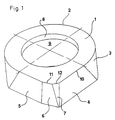
- Cutting insert comprising an upper chip surface (1), a bottom surface being substantially plane-parallel with the chip surface, and side surfaces (3, 4, 5, 6, 7) extending between those surfaces, the periphery of the cutting insert comprises two mutually substantially perpendicular side surfaces (4, 5), whereby a part of one of the two side surfaces adjacent the corner between them, forms a parallel land (6) and is inclined so that it forms an obtuse angle with both said side surfaces,
characterized in that about 3/4 of the periphery of the cutting insert is substantially circle round. - Cutting insert according to claim 1,
characterized in that the corner between the parallel land (6) and one of the side surfaces (4) is formed with a reinforcing chamfer (7). - Cutting insert according to claim 1,
characterized in that the part of the one side surface that forms the parallel land (6) constitutes between 20 and 40 % of the total original length of said side surface (5).
Applications Claiming Priority (3)
| Application Number | Priority Date | Filing Date | Title |
|---|---|---|---|
| SE9301790 | 1993-05-26 | ||
| SE9301790A SE508387C2 (en) | 1993-05-26 | 1993-05-26 | round Cut |
| PCT/SE1994/000487 WO1994027774A1 (en) | 1993-05-26 | 1994-05-25 | Rounded cutting insert |
Publications (2)
| Publication Number | Publication Date |
|---|---|
| EP0734301A1 EP0734301A1 (en) | 1996-10-02 |
| EP0734301B1 true EP0734301B1 (en) | 1998-07-29 |
Family
ID=20390054
Family Applications (1)
| Application Number | Title | Priority Date | Filing Date |
|---|---|---|---|
| EP94917238A Expired - Lifetime EP0734301B1 (en) | 1993-05-26 | 1994-05-25 | Rounded cutting insert |
Country Status (12)
| Country | Link |
|---|---|
| US (1) | US5536119A (en) |
| EP (1) | EP0734301B1 (en) |
| JP (1) | JPH07509412A (en) |
| KR (1) | KR100292969B1 (en) |
| CN (1) | CN1047974C (en) |
| CA (1) | CA2139860A1 (en) |
| DE (1) | DE69412133T2 (en) |
| ES (1) | ES2120048T3 (en) |
| PL (1) | PL173431B1 (en) |
| RU (1) | RU2114721C1 (en) |
| SE (1) | SE508387C2 (en) |
| WO (1) | WO1994027774A1 (en) |
Families Citing this family (37)
| Publication number | Priority date | Publication date | Assignee | Title |
|---|---|---|---|---|
| SE506679C2 (en) * | 1995-06-21 | 1998-01-26 | Seco Tools Ab | Cutting tools, preferably for milling |
| SE507542C2 (en) * | 1996-12-04 | 1998-06-22 | Seco Tools Ab | Milling tools and cutting part for the tool |
| US6189584B1 (en) * | 1998-08-12 | 2001-02-20 | Douglas Scott Cayce | Disposable carbide blade assembly for universal rotary cutter |
| US6155753A (en) * | 1999-07-15 | 2000-12-05 | Chang; Hsin-Tien | Fine adjusting mechanism for a cutting tool |
| SE516612C2 (en) * | 2000-06-27 | 2002-02-05 | Sandvik Ab | Adjusting mechanism for a cutter as well as tools for chip separating machining |
| US6508612B1 (en) | 2000-09-05 | 2003-01-21 | Kennametal Inc. | Milling cutter capable of using inserts of various geometrical shapes |
| US6488450B2 (en) | 2001-01-22 | 2002-12-03 | Ingersoll Cutting Tool Company | T-slot milling cutter and insert therefor |
| SE0100250L (en) * | 2001-01-30 | 2002-07-31 | Sandvik Ab | Tool holders |
| US7114890B2 (en) | 2001-02-13 | 2006-10-03 | Valenite Inc. | Cutting tool adjustment device |
| US7052214B2 (en) * | 2002-07-02 | 2006-05-30 | Janness Daniel L | Cutting insert and tool holder |
| SE526255C2 (en) * | 2003-03-14 | 2005-08-09 | Sandvik Intellectual Property | Tools and indexable inserts for fine turning of rotationally symmetrical grooves in workpieces |
| US7722297B2 (en) * | 2003-04-15 | 2010-05-25 | Tdy Industries, Inc. | Antirotation tool holder and cutting insert |
| US7322776B2 (en) * | 2003-05-14 | 2008-01-29 | Diamond Innovations, Inc. | Cutting tool inserts and methods to manufacture |
| JP4782672B2 (en) | 2003-06-03 | 2011-09-28 | サンドビック インテレクチュアル プロパティー アクティエボラーグ | Indexable cutting insert and method of manufacturing the cutting insert |
| US7220083B2 (en) | 2003-10-15 | 2007-05-22 | Tdy Industries, Inc. | Cutting insert for high feed face milling |
| US20050183893A1 (en) * | 2004-01-13 | 2005-08-25 | Sandvik Ab | Indexable cutting inserts and methods for producing the same |
| US7090585B2 (en) * | 2004-02-27 | 2006-08-15 | Kennametal Inc. | Nail manufacturing tool holder having a quick change mechanism |
| US20050271483A1 (en) * | 2004-06-02 | 2005-12-08 | Sandvik Ab | Indexable cutting inserts and methods for producing the same |
| US7452167B2 (en) * | 2004-11-26 | 2008-11-18 | Kyocera Corporation | Cutting insert and milling tool |
| DE102006025293C5 (en) * | 2006-05-31 | 2010-12-23 | Kennametal Inc. | Method of machining a wheel |
| US7410331B2 (en) * | 2006-06-29 | 2008-08-12 | Seco Tools Ab | Tool |
| US7431541B2 (en) * | 2007-01-29 | 2008-10-07 | Hsin-Tien Chang | Disposable cutting insert for boring cutter |
| US7566192B2 (en) * | 2007-10-19 | 2009-07-28 | Kennametal Inc. | Axial seating pin |
| IL193233A (en) * | 2008-08-04 | 2012-12-31 | Iscar Ltd | Cutting tool having a bidirectional adjustment mechanism |
| US9586264B2 (en) * | 2009-04-28 | 2017-03-07 | Kennametal Inc. | Double-sided cutting insert for drilling tool |
| EP2727673B1 (en) * | 2011-06-30 | 2018-05-23 | Kyocera Corporation | Cutting insert, cutting tool, and method for manufacturing cut workpiece using same |
| EP2596887B1 (en) * | 2011-11-23 | 2019-01-23 | Sandvik Intellectual Property AB | Cutting tool comprising an exchangeable insert seat member |
| US20130330136A1 (en) * | 2012-06-06 | 2013-12-12 | Iscar, Ltd. | Cutting Insert and Tool Having an Anti-Slip Arrangement |
| JP6305339B2 (en) * | 2012-08-06 | 2018-04-04 | 株式会社タンガロイ | Blade adjustment device |
| US9283626B2 (en) | 2012-09-25 | 2016-03-15 | Kennametal Inc. | Double-sided cutting inserts with anti-rotation features |
| US9011049B2 (en) | 2012-09-25 | 2015-04-21 | Kennametal Inc. | Double-sided cutting inserts with anti-rotation features |
| DE102013114124A1 (en) * | 2013-12-16 | 2015-06-18 | Hegenscheidt-Mfd Gmbh & Co. Kg | Cutting insert for profile turning and cassette for holding a cutting insert |
| GB2525620A (en) * | 2014-04-29 | 2015-11-04 | Rigibore Ltd | Cutting tool assembly |
| US9700947B2 (en) | 2014-06-27 | 2017-07-11 | Kennametal Inc. | Ballnose cutting tool and ballnose cutting insert |
| CN107538020B (en) * | 2017-09-30 | 2020-07-10 | 株洲钻石切削刀具股份有限公司 | Circular cutting blade and cutting tool with accurate positioning structure |
| CN109434173A (en) * | 2018-12-27 | 2019-03-08 | 安徽华菱汽车有限公司 | A kind of milling cutter and milling cutter adjust component |
| WO2020179538A1 (en) * | 2019-03-05 | 2020-09-10 | 京セラ株式会社 | Cutting tool, and method for producing cut workpiece |
Family Cites Families (11)
| Publication number | Priority date | Publication date | Assignee | Title |
|---|---|---|---|---|
| US280148A (en) * | 1883-06-26 | Cutter and holder for lathes | ||
| US3545061A (en) * | 1968-05-21 | 1970-12-08 | Kenneth S Michael | Cutting tool |
| FR2412375A1 (en) * | 1977-12-23 | 1979-07-20 | Diamant Ste Tech | MACHINING INSERT AND TOOL CONTAINING SUCH INSERT |
| IT1104307B (en) * | 1978-12-22 | 1985-10-21 | Templier Raymond Guy | TOOL FOR MILLING THE EDGE OF THE INSOLES FOR FOOTWEAR |
| SU904900A1 (en) * | 1980-05-20 | 1982-02-15 | Ростовский-на-Дону научно-исследовательский институт технологии машиностроения | Build-up cutting tool |
| DE3125185A1 (en) * | 1981-06-26 | 1983-01-13 | Sitzmann & Heinlein Gmbh, 8502 Zirndorf | "PLANNING KNIFE HEAD, ESPECIALLY FINISHING HEAD" |
| US4527930A (en) * | 1983-03-23 | 1985-07-09 | Hugh Harroun | Ball nose end cutting tool |
| DE3402547A1 (en) * | 1984-01-26 | 1985-08-08 | Hartmetall-Werkzeugfabrik Paul Horn GmbH, 7400 Tübingen | Exchangeable cutting body, especially for an internal-recessing and circular tool |
| JP2555019Y2 (en) * | 1990-03-30 | 1997-11-19 | 三菱マテリアル株式会社 | Throwaway cutter |
| US5123787A (en) * | 1991-02-25 | 1992-06-23 | Gte Valenite Corporation | Machining tool |
| US5188489A (en) * | 1991-05-31 | 1993-02-23 | Kennametal Inc. | Coated cutting insert |
-
1993
- 1993-05-26 SE SE9301790A patent/SE508387C2/en not_active IP Right Cessation
-
1994
- 1994-05-25 CN CN94190317A patent/CN1047974C/en not_active Expired - Fee Related
- 1994-05-25 WO PCT/SE1994/000487 patent/WO1994027774A1/en active IP Right Grant
- 1994-05-25 US US08/248,712 patent/US5536119A/en not_active Expired - Fee Related
- 1994-05-25 JP JP7500540A patent/JPH07509412A/en active Pending
- 1994-05-25 DE DE69412133T patent/DE69412133T2/en not_active Expired - Fee Related
- 1994-05-25 ES ES94917238T patent/ES2120048T3/en not_active Expired - Lifetime
- 1994-05-25 RU RU95106498A patent/RU2114721C1/en active
- 1994-05-25 CA CA002139860A patent/CA2139860A1/en not_active Abandoned
- 1994-05-25 EP EP94917238A patent/EP0734301B1/en not_active Expired - Lifetime
- 1994-05-25 KR KR1019950700296A patent/KR100292969B1/en not_active IP Right Cessation
- 1994-05-25 PL PL94307235A patent/PL173431B1/en unknown
Also Published As
| Publication number | Publication date |
|---|---|
| PL173431B1 (en) | 1998-03-31 |
| DE69412133D1 (en) | 1998-09-03 |
| SE9301790D0 (en) | 1993-05-26 |
| PL307235A1 (en) | 1995-05-15 |
| RU2114721C1 (en) | 1998-07-10 |
| SE508387C2 (en) | 1998-10-05 |
| SE9301790L (en) | 1994-11-27 |
| ES2120048T3 (en) | 1998-10-16 |
| KR100292969B1 (en) | 2001-09-17 |
| CA2139860A1 (en) | 1994-12-08 |
| EP0734301A1 (en) | 1996-10-02 |
| CN1110052A (en) | 1995-10-11 |
| WO1994027774A1 (en) | 1994-12-08 |
| DE69412133T2 (en) | 1998-12-03 |
| RU95106498A (en) | 1996-12-10 |
| US5536119A (en) | 1996-07-16 |
| KR950702462A (en) | 1995-07-29 |
| CN1047974C (en) | 2000-01-05 |
| JPH07509412A (en) | 1995-10-19 |
Similar Documents
| Publication | Publication Date | Title |
|---|---|---|
| EP0734301B1 (en) | Rounded cutting insert | |
| US5667343A (en) | Face milling cutter with recesses for adjustable insert holders | |
| EP0681515B1 (en) | A cutting insert having a helically twisted relief surface with an adjoining recess | |
| EP1597008B1 (en) | A cutting insert, a cutting tool, a shim and a method | |
| US7168512B2 (en) | Cutting insert and milling cutter with such a cutting insert | |
| US6109838A (en) | Face milling cutter and method of assembling | |
| EP1401603B1 (en) | Sintered cutting insert having center hole for clamp screw | |
| CA2156519C (en) | A chip cutting tool | |
| EP0781184B1 (en) | Drilling tool | |
| JPH09507438A (en) | Indexable insert for finishing milling and its body | |
| CA2160148A1 (en) | Milling cutter head with serrated cartridges | |
| CA1260689A (en) | On-edge end-milling insert | |
| US5871309A (en) | Milling cutter body and methods for assembling same | |
| JP3319349B2 (en) | Indexable inserts and indexable milling tools | |
| EP1584409B1 (en) | Cutting insert | |
| JP2001219314A (en) | Throw-away tip | |
| JPH01264702A (en) | Cutting tool |
Legal Events
| Date | Code | Title | Description |
|---|---|---|---|
| PUAI | Public reference made under article 153(3) epc to a published international application that has entered the european phase |
Free format text: ORIGINAL CODE: 0009012 |
|
| 17P | Request for examination filed |
Effective date: 19950608 |
|
| AK | Designated contracting states |
Kind code of ref document: A1 Designated state(s): DE ES FR GB IT SE |
|
| GRAG | Despatch of communication of intention to grant |
Free format text: ORIGINAL CODE: EPIDOS AGRA |
|
| GRAG | Despatch of communication of intention to grant |
Free format text: ORIGINAL CODE: EPIDOS AGRA |
|
| GRAH | Despatch of communication of intention to grant a patent |
Free format text: ORIGINAL CODE: EPIDOS IGRA |
|
| 17Q | First examination report despatched |
Effective date: 19971014 |
|
| GRAH | Despatch of communication of intention to grant a patent |
Free format text: ORIGINAL CODE: EPIDOS IGRA |
|
| GRAA | (expected) grant |
Free format text: ORIGINAL CODE: 0009210 |
|
| AK | Designated contracting states |
Kind code of ref document: B1 Designated state(s): DE ES FR GB IT SE |
|
| REF | Corresponds to: |
Ref document number: 69412133 Country of ref document: DE Date of ref document: 19980903 |
|
| REG | Reference to a national code |
Ref country code: ES Ref legal event code: FG2A Ref document number: 2120048 Country of ref document: ES Kind code of ref document: T3 |
|
| ET | Fr: translation filed | ||
| PLBE | No opposition filed within time limit |
Free format text: ORIGINAL CODE: 0009261 |
|
| STAA | Information on the status of an ep patent application or granted ep patent |
Free format text: STATUS: NO OPPOSITION FILED WITHIN TIME LIMIT |
|
| 26N | No opposition filed | ||
| PGFP | Annual fee paid to national office [announced via postgrant information from national office to epo] |
Ref country code: SE Payment date: 20010417 Year of fee payment: 8 |
|
| PGFP | Annual fee paid to national office [announced via postgrant information from national office to epo] |
Ref country code: FR Payment date: 20010518 Year of fee payment: 8 |
|
| PGFP | Annual fee paid to national office [announced via postgrant information from national office to epo] |
Ref country code: DE Payment date: 20010522 Year of fee payment: 8 |
|
| PGFP | Annual fee paid to national office [announced via postgrant information from national office to epo] |
Ref country code: GB Payment date: 20010523 Year of fee payment: 8 |
|
| PGFP | Annual fee paid to national office [announced via postgrant information from national office to epo] |
Ref country code: ES Payment date: 20010530 Year of fee payment: 8 |
|
| REG | Reference to a national code |
Ref country code: GB Ref legal event code: IF02 |
|
| PG25 | Lapsed in a contracting state [announced via postgrant information from national office to epo] |
Ref country code: GB Free format text: LAPSE BECAUSE OF NON-PAYMENT OF DUE FEES Effective date: 20020525 |
|
| PG25 | Lapsed in a contracting state [announced via postgrant information from national office to epo] |
Ref country code: SE Free format text: LAPSE BECAUSE OF NON-PAYMENT OF DUE FEES Effective date: 20020526 Ref country code: ES Free format text: LAPSE BECAUSE OF NON-PAYMENT OF DUE FEES Effective date: 20020526 |
|
| PG25 | Lapsed in a contracting state [announced via postgrant information from national office to epo] |
Ref country code: DE Free format text: LAPSE BECAUSE OF NON-PAYMENT OF DUE FEES Effective date: 20021203 |
|
| EUG | Se: european patent has lapsed | ||
| GBPC | Gb: european patent ceased through non-payment of renewal fee |
Effective date: 20020525 |
|
| PG25 | Lapsed in a contracting state [announced via postgrant information from national office to epo] |
Ref country code: FR Free format text: LAPSE BECAUSE OF NON-PAYMENT OF DUE FEES Effective date: 20030131 |
|
| REG | Reference to a national code |
Ref country code: FR Ref legal event code: ST |
|
| REG | Reference to a national code |
Ref country code: ES Ref legal event code: FD2A Effective date: 20030611 |
|
| PG25 | Lapsed in a contracting state [announced via postgrant information from national office to epo] |
Ref country code: IT Free format text: LAPSE BECAUSE OF NON-PAYMENT OF DUE FEES;WARNING: LAPSES OF ITALIAN PATENTS WITH EFFECTIVE DATE BEFORE 2007 MAY HAVE OCCURRED AT ANY TIME BEFORE 2007. THE CORRECT EFFECTIVE DATE MAY BE DIFFERENT FROM THE ONE RECORDED. Effective date: 20050525 |