EP0734126A1 - Compression en deux temps par codages RLE puis Lempel-ZIV - Google Patents
Compression en deux temps par codages RLE puis Lempel-ZIV Download PDFInfo
- Publication number
- EP0734126A1 EP0734126A1 EP96301291A EP96301291A EP0734126A1 EP 0734126 A1 EP0734126 A1 EP 0734126A1 EP 96301291 A EP96301291 A EP 96301291A EP 96301291 A EP96301291 A EP 96301291A EP 0734126 A1 EP0734126 A1 EP 0734126A1
- Authority
- EP
- European Patent Office
- Prior art keywords
- data
- tokens
- compressor
- compression
- byte
- Prior art date
- Legal status (The legal status is an assumption and is not a legal conclusion. Google has not performed a legal analysis and makes no representation as to the accuracy of the status listed.)
- Withdrawn
Links
Images


Classifications
-
- H—ELECTRICITY
- H03—ELECTRONIC CIRCUITRY
- H03M—CODING; DECODING; CODE CONVERSION IN GENERAL
- H03M7/00—Conversion of a code where information is represented by a given sequence or number of digits to a code where the same, similar or subset of information is represented by a different sequence or number of digits
- H03M7/30—Compression; Expansion; Suppression of unnecessary data, e.g. redundancy reduction
- H03M7/3084—Compression; Expansion; Suppression of unnecessary data, e.g. redundancy reduction using adaptive string matching, e.g. the Lempel-Ziv method
- H03M7/3086—Compression; Expansion; Suppression of unnecessary data, e.g. redundancy reduction using adaptive string matching, e.g. the Lempel-Ziv method employing a sliding window, e.g. LZ77
-
- G—PHYSICS
- G06—COMPUTING; CALCULATING OR COUNTING
- G06T—IMAGE DATA PROCESSING OR GENERATION, IN GENERAL
- G06T9/00—Image coding
- G06T9/005—Statistical coding, e.g. Huffman, run length coding
-
- G—PHYSICS
- G06—COMPUTING; CALCULATING OR COUNTING
- G06V—IMAGE OR VIDEO RECOGNITION OR UNDERSTANDING
- G06V10/00—Arrangements for image or video recognition or understanding
- G06V10/40—Extraction of image or video features
- G06V10/42—Global feature extraction by analysis of the whole pattern, e.g. using frequency domain transformations or autocorrelation
- G06V10/421—Global feature extraction by analysis of the whole pattern, e.g. using frequency domain transformations or autocorrelation by analysing segments intersecting the pattern
-
- H—ELECTRICITY
- H03—ELECTRONIC CIRCUITRY
- H03M—CODING; DECODING; CODE CONVERSION IN GENERAL
- H03M7/00—Conversion of a code where information is represented by a given sequence or number of digits to a code where the same, similar or subset of information is represented by a different sequence or number of digits
- H03M7/30—Compression; Expansion; Suppression of unnecessary data, e.g. redundancy reduction
- H03M7/46—Conversion to or from run-length codes, i.e. by representing the number of consecutive digits, or groups of digits, of the same kind by a code word and a digit indicative of that kind
Definitions
- the present invention relates generally to systems and methods for compressing data. More particularly, the present invention relates to providing an improved system and method for compressing binary format serial input data, such as, for example, bit mapped image data.
- Digital data compression is a technology experiencing accentuated interest in recent years. In part, this is a consequence of the growing use of personal computers and workstations with high resolution graphic display systems.
- the volume of digital data used to represent the video information, as well as the speed with which that data must be compressed and decompressed, in the course of storage, transmission or physical rendering has motivated significant investigation in the technologies relating to data compression.
- the use of data compression increases the effective storage capacity of hard disks and CD drive systems, and is particularly important for compact non-volatile solid state storage devices such as PCMCIA cards.
- the transmission of data in compressed form increases the effective bandwidth of the media.
- hardware constraints often require that images be stored for access as complete units. Laser printers are an example of where data compression allows the use of smaller buffer memories to store full images.
- the fundamental concepts which characterize these and other versions of the basic LZ-1 algorithm involve the use of a buffer to store received data and to identify matches between newly received strings of data and previously received and processed strings of data.
- new strings of data typically sequences of bytes representing alpha numeric characters which match preceeding strings can be encoded simply by reference to these prior strings, using just location and length data incorporated into what are commonly known as tokens.
- the LZ-1 algorithm is dynamic in that new data is entered into the buffer which stores the earlier data after the comparison and encoding of the new data is completed.
- the size of the buffer is analogous to a sliding window over a data stream in which the new data characters are always compared to previously received characters within the length of the window.
- the encoded output is either a raw/literal token, indicating no compression, or a compressed/string token, the latter providing a length and an offset identifying the previously existing matching character string within the window.
- the algorithm is increasingly effective as the size of the window increases and the repetition rate of the patterns in the data characters within the window increases.
- US Patent Application Serial No. 08/290,451 relates to a use of a content addressable memory (CAM) to accelerate the comparison of new data with previously received strings of data.
- CAM content addressable memory
- the present invention provides a digital data lossless compression apparatus, comprising: first compression means for receiving binary format serial input data from a source and run length compressing the serial input data into first data units of fixed size with sequentially related binary values; second compression means for receiving the first data units of fixed size and Lempel-Ziv sliding window compressing the first data units of fixed size into tokens of both fixed size types and variable size types; and means for transmitting the tokens.
- the present invention provides a method of losslessly compressing digital data, comprising the steps of: receiving binary format serial input data; run length compressing the received binary format serial input data into first data units of fixed size with sequentially related binary values; Lempel-Ziv sliding window compressing the first data units of fixed size into tokens of both fixed size types and variable size types; and transmitting the tokens.
- the present invention provides the desired efficient and timely compression and decompression of data such as bit mapped image data through a digital data lossless compression apparatus, which acts upon a source of binary format serial input data using a first compression means for receiving the serial input data and run length compressing the binary format serial input data into first data units of fixed size and sequentially defined binary values, a second compression means for receiving the first data units of fixed size and Lempel-Ziv sliding window compressing the first data units of fixed size into tokens of both fixed size types and variable size types, and means for transmitting the tokens.
- the invention also relates to methods for accomplishing the corresponding features of this apparatus.
- the invention relates to multiple stage compression and decompression, where the binary bit mapped image as input data is first subject to run length compression to form a succession of fixed size units containing binary value information about the image pixels.
- the run length compressed units of fixed size serve as the input to the LZ-1 compressor.
- the tokens from the LZ-1 compressor are transmitted to a storage medium or over a communication medium. Compression efficiency is accentuated in two respects.
- an efficient run length compression technique conveys the full binary value information while using data units of fixed byte size.
- the application of LZ-1 further compresses such data units.
- the fundamental match between the LZ-1 compressor input and the embodying run length compression output provides exceptional compression ratios for binary bit mapped format image data, which compression ratios increase as the resolution of the image data increases.
- the present invention provides a system and method for optimally combining run length compression concepts with sliding window type Lempel-Ziv data compression to accentuate the lossless compression of digital bit mapped image data of the type routinely created, transmitted, stored and printed using data processing systems.
- Fig. 1 schematically depicts by functional block diagram the broad context within which the invention can be practiced. However, it is not intended to be all encompassing given the applicability of lossless digital data compression. Furthermore, the compression and decompression described with reference to the preferred embodiment of the present invention is not limited to being implemented within the workstation, whether that be by hardware or software, but may be resident in the individual functional subsections either as a whole, including both compression and decompression functions, or only in part.
- Fig. 1 shows that workstation 1 is connected to a video display system 2 and is communicatively coupled to a bus 3 so as to provide bidirectional digital data transmission capabilities to and from CD drive 4, hard disk or PCMCIA card nonvolatile memory 6, network and communication system 7, and printer 8.
- the preferred embodiment set forth hereinafter is described with reference to the efficient manipulation of digital format binary bit mapped images as conveyed to printer 8 for rendering into physical form.
- the particulars of the preferred example involve a transmission of the binary bit mapped image over bus 3 to high resolution laser printer 8. It should be apparent that for grey scale and color images, the image data would involve multiple bits per pixel position.
- the objective of the invention is to improve the lossless compression efficiency, and in preferred embodiments to improve and extend the capabilities of the LZ-1 technique as applied to bit mapped images.
- the desirable compression and decompression attributes of the LZ-1 can be retained with bit mapped images, heretofore not a forte of the LZ-1 compression technique.
- the preferred embodiment contemplates the introduction of a run length type precompressor or preprocessor between the binary bit mapped image input data and the input to the LZ-1 compressor.
- the embodying precompressor stage is also lossless and is configured to compress input data with minimal complexity and to provide an output of data in a format particularly suited for LZ-1 compression. Since the efficiency of decompression is an important consideration, the corresponding run length decompressor, situated between the LZ-1 decompressor and the output of the stored binary bit mapped image data, is likewise accomplished with minimum complexity.
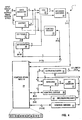
- Fig. 2 depicts by functional block diagram a preferred implementation of the invention.
- the input of binary bit mapped image data enters run length compressor 9, for precompression and structuring into a format particularly usable by LZ-1 compressor 11.
- the tokens generated by LZ-1 compressor 11 are conveyed to memory 12, which as noted earlier can in a broader sense be an aspect of a printer or a communications system.
- Lossless decompression of the stored tokens into binary bit mapped image data commences in LZ-1 decompressor 13.
- LZ-1 decompressor 13 As noted earlier, the asymmetric simplicity of LZ-1 decompression, in contrast to compression, provides the tremendous speed sought when decompressing data stored in memory.
- Run length decompressor 14 is similarly efficient in decoding data provided by LZ-1 decompressor 13. Since decompression as implemented in run length decompressor 14 is a relatively simple operation, speed in the implementation follows.
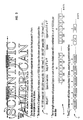
- Fig. 3 illustrates by way of abbreviated example the successive compression operations as would be performed in run length compressor 9 and LZ-1 compressor 11 on an example piece of binary bit mapped image corresponding to the artistically rendered magazine title "SCIENTIFIC AMERICAN". Resolution is presumed to be 1200 dpi. For the example, the focus of the attention is on the letters "IE" and "IF" as defined along scan line 16.
- the body of the "I” is composed of 155 ls, representing the black area, followed by 225 0s, representing the white space between the "I” and “E” letters, followed in succession by 155 1s for the body of the "E” (or the corresponding body of the "F") letters followed thereafter by 187 0s for the intervening space, and concluding with 94 ls for the upper serif of the "E” (or "F") letters.
- the bits depicted at 17 represent the raw binary bit mapped image data along scan line 16 of either the "IE" or "IF" letter combinations.
- Run length compressor 9 in Fig. 2 encodes consecutive runs of identical data bits into one or more data units (fields) individually of fixed byte size.
- the data run typically representing a scan line such as 16 through an image. Where the data run starts with a value of 0, and each binary value run extends along the scan line to a length of less than 254 pixel positions, the encoded byte units are merely the run lengths, in alternating succession, beginning with the number of 0s for the first byte and alternating thereafter in 1 0 1 0 ... succession.
- One unused byte value (255) is an escape code. It is used to denote that the run is more than 254 pixels in length, and is therefore continued in the next succeeding unit.
- the raw binary bit mapped data at 17 in Fig. 3 is run length compressed to produce the byte size units generally at 18.
- the first group of 5 bytes represents the letters "IE” along scan line 16
- the second group of 5 bytes represents the letters "IF” along scan line 16 in run length compressed form.
- the original 1632 bits representing the two sets of letter combinations has been compressed into a total of 80 bits, 40 bits each for the "IE" and "IF” letter combinations. That represents a compression of approximately 20:1.
- the data units from the run length compressor are all of byte size, though the content of each byte differs depending upon the length of the original binary bit string along the scan line.
- the LZ-1 compressor is particularly adapted to the efficient compression of byte size input data.
- the output of LZ-1 compressor 11 in Fig. 2 for the run length compressed data at 18 in Fig. 3 is shown at 19.
- the tokens generated by the LZ-1 compressor presume that the compressor has a 512 byte history table, which size is in the moderate range.
- the first group of tokens, representing the "IE" information along scan line 16 are comprised of a zero bit, to indicate a raw or literal token, followed by the byte of data from the run length compressor. Since the "IE" byte string at 18 resides within the history table when the "IF" byte string is evaluated for matches, byte string matches will be identified. For each matching string of bytes, a compressed/string token is issued.
- Such token includes a 1 followed by a value 4 binary string, representing that the length of the match is 5, and concludes with a displacement value using 8 bits to identify the location of the prior matched string.
- the 8 bits is related to the 512 byte size of the history table.
- the original binary bit mapped information for the combination of the "IE" and "IF" sections of scan line 16 is thereby compressed to 59 bits, a composite compression ratio of approximately 28:1.
- Fig. 4 depicts by functional block diagram run length compressor 9 as first shown in Fig. 2.
- Data register 21 can either be loaded directly with an input of binary image data in bytes or loaded from shifter 22 upon a left shift of data responsive to control decode 23.
- XOR 24 allows the use of the same decoder/encoder 26 irrespective of whether runs of 0s or 1s are being processed.
- XOR 24 is responsive to 1 bit toggle 27 as specified in master control store 28. When the toggle is set, the inverse of the content from data register 21 is generated by the XOR for decoder/encoder 26.
- the true/inverse output from XOR 24 is combined with the output from bit counter 29, decoded and then reencoded in block 26 to generate a 4 bit address directed to control store 28.
- the 4 bits from decoder/encoder 26 represent 9 possible equations for the bytes of data in data register 21, as defined in Table A.
- Bits 04, 05 and 06 from control store memory 28 control the load and shift operations in data register 21.
- the control signals are decoded by control decoder 23 and then are used to control shifter 22 and data register 21 as defined in Table B.
- TABLE B 04 05 06 OPERATION 0 0 0
- Load from input data bus 0 0 1 Shift 1 bit to left 0 1 0 Shift 2 bits to left 0 1 1 Shift 3 bits to left 1 0 0 Shift 4 bits to left 1 0 1 Shift 5 bits to left 1 1 0 Shift 6 bits to left 1 1 1 Shift 7 bits to left
- bit 07 from control store 28 is used to control toggle 27.
- the remaining bits 08, 09 and 10 from control store 28 are loaded into bit counter 29 with each cycle to reflect the number of bits in data register 21 which are now valid after the shift specified by control store bits 04, 05 and 06.
- the 13 bits from control store 28 are summarized in Table C, showing their functions and blocks they control. TABLE C 00 (Bit counter, add/load 01 ( 02 ( 03 ( 04 (Data register, load/shift 05 ( 06 ( 07 (0/1, toggle 08 (New bit count value 09 ( 10 ( 11 (Output control 12 (
- output control bits 11 and 12 are decoded in control decoder 31 and thereupon used to control output register 32.
- Output register 32 is loaded from bit counter 33, the output of which is decoded by decoder/encoder 34 into a 3 bit address directed to control store memory 28.
- Control store output bits 00, 01, 02 and 03 are used to either add or load a value into bit counter 33 based upon the state decoded in control decode 36 as applied to add/load block 37.
- the operations and values associated with control store bits 01-03 are set forth in Table E.
- Control store output bits 11 load the incremented value of bit counter 33 into output register 32.
- Bits 12, which are decoded together with bit 11 in control decode 31, load the value 255 into output register 32.
- count byte values of 1 through 254 from output register 32 specify a run count of 1 through 254. Successive bit count fields within this value range represent runs of successively opposite binary values. Thus, if a run of 0s is specified by the first byte and has a range of 1 through 254, the next byte will always specify a run of ls, and vice versa.
- the byte value 255 is used for those situations where a longer run than 254 is encountered in the input data stream. That number indicates that the current binary value run is longer than 254 bits, and that the excess length above the value 254 is encoded in the next successive byte. Long runs are thereby encoded as a series of bytes with the value 255, terminating with a byte of a value in the range of 1 through 254.
- the byte value 0 is reserved for those situations where the input data is actually started with a binary 1 bit mapped value. It could be thought of as specifying a run length of 0 0s, the next byte then being the actual run count for the ls that start the data stream.
- the byte value 0 can also be used as a terminating byte, if needed, since it is normally not coded in any other position other than the first.
- run length compressor as embodied herein allows for a maximum data compression of 32:1, given that approximately 32 bytes of input data can be encoded into a single byte size unit if the input data is consistently all 0s or all 1s. Conversely, however, input data consisting of strictly alternating 0s and 1s would expand, as encoded herein, in that each bit encodes to a single byte. For that reason, run length compression of the present form is particularly suited for business, financial or medical form type image data. Such images exhibit significant regional repetition. The other end of the spectrum, namely those pages likely to exhibit significantly less compression, are characterized by graphic images with numerous random patterns.
- Binary bit mapped image data which is run length compressed in the manner described hereinbefore, is provided in byte format as the input to the LZ-1 stage of the dual stage compressor to which the preferred embodiment of the present invention pertains. See Fig. 2. Though multiple stage compressors have been disclosed, such as in U.S. Patent Nos. 4,316,222, 4,971,407, 4,626,829 and 5,109,433, there has not been an appreciation for the benefits that can accrue when the output format of the first compressor is optimally matched to the input format of the second compressor. As noted earlier, the selection of fixed size units as the outputs from run length compressor 9 and the corresponding inputs to LZ-1 compressor 11 compliments the operations of each in an optimizing manner.
- Fig. 5A depicts a representative LZ-1 compressor architecture. As shown, the architecture coincides with that described in the aforementioned U.S. Patent application Serial No. 08/290,451.
- the key aspect of the implementation relates to the use of a content addressable memory (CAM) to compare incoming strings of data with previously received and processed data as stored in the CAM memory. As would be expected by the presence of the CAM, this embodiment focuses on a hardware implementation of LZ-1 compressor 11 (Fig. 2).
- CAM content addressable memory
- the CAM form of the LZ-1 compressor depicted in Fig. 5A is managed by control circuit 38, which control circuit is connected to each of the elements in Fig. 5A while operating as a state machine.
- the Lz-1 input data enters input data buffer 39 and is later stored in backup data buffer 41.
- the data stored in input data buffer 39 is compared with all current entries in CAM array 42.
- the CAM array includes multiple sections (N+1 sections being shown in the figure) with each section including a register and a comparator as more clearly illustrated in Fig. 5B.
- Each CAM array register stores a byte of data and includes a single cell 43 for indicating whether a valid or current data byte is stored in the CAM array register.
- Each comparator generates a match or active signal when the data bytes stored in the corresponding CAM array register match the data bytes stored in the input data buffer 39, with some refinements.
- a write select shift register coupled to the CAM array is a write select shift register (WS), identified by reference numeral 44, with one write select cell for each section of the CAM array.
- WS write select shift register
- a single write cell is set to a 1 value while the remaining cells are all set to 0 values.
- the active write select cell the cell having a 1 value, selects which section of the CAM array will be used to store the data byte currently held in input data buffer 31.
- Write select shift register 44 is shifted one cell for each new data byte entered into input data buffer 39. The use of shift register 44 to select allows the use of fixed addressing within CAM array 42.
- Current entries in the CAM array are designated as those CAM array sections that have empty cells (EC) 43 set to 1 and have corresponding write select (WS) cells 44 set to 0. If the data in any of the current CAM entries matches the data byte in input data buffer 41, then the comparator for the CAM array section generates an active match signal on the corresponding match line 45. Thereupon, match OR gate 47, which is connected to each of the match lines, generates an overall match signal.
- the primary selector shift register (PS) 48 identifies the sections in the CAM array where a successful match has been identified. Thereby, PS cells which are set to 1, the active state, indicate which CAM array sections contain the last word of a matching string, or a sequence, of data bytes.
- Multiple cells in the PS column 48 may be active at any one time because a number of locations in the CAM array may have detected matches with incoming data bytes. If no previous matches are detected for incoming data bytes, a raw or literal token is generated by LZ-1 compressor 11, preferably composed of 9 bits beginning with a 0 prefix and followed by the 8 bit byte of the raw data.
- the next input data byte is loaded into input data buffer 39 and compared to all current entries in the CAM array as described previously.
- the match lines for all CAM array data cell entries that match the new data byte become active upon comparison. If any match line is active, then match OR gate 47 will also be active. All active primary selector cells 48 whose corresponding match lines are not active are then cleared. If any of the primary selector cell entries remains active, indicating that the current data byte in input data buffer 39 extends the previous matching string of data bytes, then primary selector OR gate 52 becomes active. Gate 52 is connected to each of the primary selector cells 48. Thereby, an input data byte is processed to determine whether it continues a previously identified match string.
- the matching process continues until there is a 0 at the output of the primary selector OR gate 52, signifying that there are no matches left.
- the values marking the end points of all the matching strings which existed prior to the last data byte are still stored in secondary selector cells 49.
- Address generator 53 determines the location of one of the matching strings and generates its address. Address generator 53 is readily designed to generate an address using signals from one or more cells of the secondary selector 49. The length of the matching string is available in length counter 51.
- Address generator 53 generates the fixed address for the CAM array section containing the end of the matching string, while length counter 51 provides the length of the matching string. A start address and length of the matching string is then calculated, coded and output as a compressed or string token.
- Fig. 5B contains a schematic block diagram illustrating in somewhat greater detail a sample section of the CAM array and directly associated write select cell, empty cell, primary selector cell and secondary selector cell. Connections between the representative cells, the CAM register and the comparator are fully shown.
- the parallel processing capability of the CAM implementation in Fig. 5A provides an extremely fast compression as well as an exhaustive search of the data within the history window. Incoming data bytes are compared to all possible candidates within the history simultaneously.
- the CAM array holds the current history. During the search part of each cycle, the system marks all locations where a match is found to the incoming data by setting corresponding bits in primary select shift register 48.
- Write select shift register 44 normally has only a single bit, which defines the CAM array location subject to update with the incoming data byte during the new data entry segment of each cycle. At the conclusion of each cycle, the write select and primary select shift registers are shifted by one bit position in preparation for receiving and processing the next byte of data.
- Address decoder 53 functions as a RAM.
- the embodiment of Fig. 5A includes both encoding and decoding features.
- Fig. 6 illustrates by function block diagram an alternate implementation of LZ-1 compressor 11, as identified by reference numeral 11X.
- the LZ-1 compressor implementation in Fig. 6 utilizes a character history bit pattern memory in contrast to the use of a CAM. The difference coincides with the distinction between a software implementation, this version, versus a hardware implementation, the CAM array version, of the LZ-1 compressor.
- the illustrated LZ-1 compressor 11X represents the embodiment described in the aforementioned U.S. Patent Application Serial No. 08/355,865, which further extended concepts described in the aforementioned U.S. Patent Application Serial No. 08/173,738.
- the LZ-1 compressor 11X in Fig. 6 includes character history bit pattern memory 54, which will typically be a uniquely defined section of a cache or main memory within a computer system.
- state machine 56 programmed within the computer, undertakes specified operations within the system by generating control signals for sending data to related functional elements.
- Character history bit pattern memory 54 stores marker bits at locations in the matrix coincident with new data characters (specifying a row address), and the order of occurrence of that character as defined by circular pointer 57 indexed or incremented with the processing of new units. Pointer 57 identifies the column position of the marker corresponding to each new data unit. Addressing of the markers in memory 54 is responsive to update and read signals generated by state machine 56, as implemented through the read/update select section 58 of memory 54.
- Block 59 is enabled by state machine 11 to perform a bit-wise AND operation on a row from memory 54 with a corresponding string of bits from the old string occurrence register of register block 61, and to provide the outcome by bit to the new string occurrence register within block 61.
- the copy logic in block 59 is selectively enabled by state machine 56 to convey a row of marker data bits to the new string occurrence register of block 61.
- Block 61 of registers also includes a circular bit shift register and copy register, both also enabled by state machine 11.
- the shifted and copied marker bits are selectively transferred from the new string occurrence register in block 61 to the old string occurrence register in block 61.
- An efficient way to accomplish the shifting between registers is to ping/pong two registers during operation.
- match length block 62 As state machine 56 cycles with the receipt of new fixed length data units, matches to strings of previously received data units, as represented by the pattern of markers in character history bit pattern memory 54, are counted in match length block 62.
- Encoder 63 immediately generates an output token of raw/literal form when the data is not compressed. In contrast, when the encoder output is to be a compressed/string token, the issuance is delayed until the maximum possible length of the matching input data string is attained for each token.
- the length of the compressed/string token is provided by block 62, while the location of the matching data unit string is derived from a set bit index in the old string occurrence register of block 61.
- the dual stage lossless compressor to which the preferred embodiment of the invention pertains is particularly efficient in compressing bit mapped image data as a consequence of a synergistic compatibility between form of the output data from the first compressor stage, the run length compressor, and the form of ideal input data to the second compressor stage, the LZ-1 compressor, as effects their composite ability to efficiently compress data.
- the first stage run length compressor operates efficiently on binary bit mapped image data and provides as an output a succession of fixed length data units, preferably of byte size.
- the complementing stage LZ-1 compressor receives the fixed length data units from the first compressor in a form which the LZ-1 compressor is particularly capable of efficiently compressing. Namely, the units are of fixed length and when defining video images are characterized by repetitive groupings.
- the asymmetry of the LZ-1 compressor and simplicity of the run length compressor provides fast decompression even with dual stage processing. Therefore, the composite is particularly suited to systems in which the data storage resources are limited and decompression must be accomplished with relative speed.
Landscapes
- Engineering & Computer Science (AREA)
- Theoretical Computer Science (AREA)
- Physics & Mathematics (AREA)
- General Physics & Mathematics (AREA)
- Multimedia (AREA)
- Computer Vision & Pattern Recognition (AREA)
- Compression, Expansion, Code Conversion, And Decoders (AREA)
- Compression Of Band Width Or Redundancy In Fax (AREA)
Applications Claiming Priority (2)
| Application Number | Priority Date | Filing Date | Title |
|---|---|---|---|
| US409766 | 1989-09-20 | ||
| US08/409,766 US5627534A (en) | 1995-03-23 | 1995-03-23 | Dual stage compression of bit mapped image data using refined run length and LZ compression |
Publications (1)
| Publication Number | Publication Date |
|---|---|
| EP0734126A1 true EP0734126A1 (fr) | 1996-09-25 |
Family
ID=23621873
Family Applications (1)
| Application Number | Title | Priority Date | Filing Date |
|---|---|---|---|
| EP96301291A Withdrawn EP0734126A1 (fr) | 1995-03-23 | 1996-02-27 | Compression en deux temps par codages RLE puis Lempel-ZIV |
Country Status (3)
| Country | Link |
|---|---|
| US (1) | US5627534A (fr) |
| EP (1) | EP0734126A1 (fr) |
| JP (1) | JPH08275000A (fr) |
Cited By (16)
| Publication number | Priority date | Publication date | Assignee | Title |
|---|---|---|---|---|
| WO1997009930A1 (fr) * | 1995-09-13 | 1997-03-20 | Medison Co., Ltd. | Appareil de diagnostic par ultrasons a compression et enregistrement de donnees dans une memoire cine |
| EP0849722A2 (fr) * | 1996-12-19 | 1998-06-24 | Deutsche Thomson-Brandt Gmbh | Méthode et dispositif de remplacement de parties d'une image codée numériquement |
| EP0903867A1 (fr) * | 1997-09-19 | 1999-03-24 | International Business Machines Corporation | Méthode et dispositif de compression adaptative de données à efficacité de compression améliorée |
| EP0957586A1 (fr) * | 1998-05-15 | 1999-11-17 | Algorithmic Research BV. | Méthode de compression de données |
| WO1999062052A2 (fr) * | 1998-05-27 | 1999-12-02 | Microsoft Corporation | Systeme et procede pour le codage entropique de coefficients a transformee quantifies d'un signal |
| WO2000054412A1 (fr) * | 1999-03-08 | 2000-09-14 | Unisys Corporation | Procede de compression de donnees et appareil a codage rlc integre |
| WO2000065724A1 (fr) * | 1999-04-27 | 2000-11-02 | Unisys Corporation | Procede et appareil de compression de donnees a codage en longueur de ligne au moyen d'un traitement de programme mathematique |
| WO2001013523A1 (fr) * | 1999-08-12 | 2001-02-22 | Unisys Corporation | Appareil et procede pour la compression de donnees lzw (lempel-ziv-welch), reposant sur un traitement mathematique des passages par anticipation |
| EP1148649A1 (fr) * | 2000-04-17 | 2001-10-24 | I-Data International A/S | Procédé et appareil destinés à la compression de données |
| EP0783208B1 (fr) * | 1996-01-02 | 2002-11-06 | Peerless Systems Corporation | Méthode et dispositif pour l'encodage à double longueur de plage de données numériques |
| WO2006070925A1 (fr) * | 2004-12-28 | 2006-07-06 | Casio Electronics Manufacturing Co., Ltd. | Dispositif et procede de compression et de decompression selectives et format de donnees pour donnees comprimees |
| US7792152B1 (en) | 2004-06-08 | 2010-09-07 | Owlink Technology, Inc. | Scheme for transmitting video and audio data of variable formats over a serial link of a fixed data rate |
| EP2842231A1 (fr) * | 2012-04-27 | 2015-03-04 | Broadcom Corporation | Procédé, appareil et programme informatiques destinés au codage d'une chaîne de bits |
| CN105164923A (zh) * | 2013-03-01 | 2015-12-16 | 古如罗技微系统公司 | 熵修正器及方法 |
| WO2017052758A1 (fr) * | 2015-09-25 | 2017-03-30 | Intel Corporation | Architecture de compression hétérogène pour rapport de compression optimisé |
| US20190228949A1 (en) * | 2018-01-25 | 2019-07-25 | Fei Company | Innovative imaging technique in transmission charged particle microscopy |
Families Citing this family (33)
| Publication number | Priority date | Publication date | Assignee | Title |
|---|---|---|---|---|
| US5805086A (en) * | 1995-10-10 | 1998-09-08 | International Business Machines Corporation | Method and system for compressing data that facilitates high-speed data decompression |
| US5875454A (en) * | 1996-07-24 | 1999-02-23 | International Business Machiness Corporation | Compressed data cache storage system |
| KR100463001B1 (ko) * | 1997-02-17 | 2005-04-25 | 주식회사 팬택앤큐리텔 | 발생위치가무작위인점들의위치정보부호화방법 |
| US5874908A (en) * | 1997-09-19 | 1999-02-23 | International Business Machines Corporation | Method and apparatus for encoding Lempel-Ziv 1 variants |
| US5877711A (en) * | 1997-09-19 | 1999-03-02 | International Business Machines Corporation | Method and apparatus for performing adaptive data compression |
| US6301394B1 (en) * | 1998-09-25 | 2001-10-09 | Anzus, Inc. | Method and apparatus for compressing data |
| US6195024B1 (en) | 1998-12-11 | 2001-02-27 | Realtime Data, Llc | Content independent data compression method and system |
| US6624761B2 (en) | 1998-12-11 | 2003-09-23 | Realtime Data, Llc | Content independent data compression method and system |
| US6604158B1 (en) | 1999-03-11 | 2003-08-05 | Realtime Data, Llc | System and methods for accelerated data storage and retrieval |
| US6601104B1 (en) | 1999-03-11 | 2003-07-29 | Realtime Data Llc | System and methods for accelerated data storage and retrieval |
| US20010047473A1 (en) | 2000-02-03 | 2001-11-29 | Realtime Data, Llc | Systems and methods for computer initialization |
| US20030191876A1 (en) * | 2000-02-03 | 2003-10-09 | Fallon James J. | Data storewidth accelerator |
| US6748520B1 (en) * | 2000-05-02 | 2004-06-08 | 3Com Corporation | System and method for compressing and decompressing a binary code image |
| US7417568B2 (en) | 2000-10-03 | 2008-08-26 | Realtime Data Llc | System and method for data feed acceleration and encryption |
| US8692695B2 (en) | 2000-10-03 | 2014-04-08 | Realtime Data, Llc | Methods for encoding and decoding data |
| US9143546B2 (en) | 2000-10-03 | 2015-09-22 | Realtime Data Llc | System and method for data feed acceleration and encryption |
| GB0102572D0 (en) * | 2001-02-01 | 2001-03-21 | Btg Int Ltd | Apparatus to provide fast data compression |
| US7386046B2 (en) * | 2001-02-13 | 2008-06-10 | Realtime Data Llc | Bandwidth sensitive data compression and decompression |
| US7110525B1 (en) | 2001-06-25 | 2006-09-19 | Toby Heller | Agent training sensitive call routing system |
| DE10301362B4 (de) * | 2003-01-16 | 2005-06-09 | GEMAC-Gesellschaft für Mikroelektronikanwendung Chemnitz mbH | Blockdatenkompressionssystem, bestehend aus einer Kompressionseinrichtung und einer Dekompressionseinrichtung, und Verfahren zur schnellen Blockdatenkompression mit Multi-Byte-Suche |
| US7313817B2 (en) * | 2003-06-17 | 2007-12-25 | Lockheed Martin Corporation | Data transmission system utilizing efficient complexity estimation of the kolmogorov complexity for data transmission |
| CN1301596C (zh) * | 2003-06-24 | 2007-02-21 | 致伸科技股份有限公司 | 数字图像数据的压缩与解压缩方法 |
| US6903668B1 (en) * | 2003-11-18 | 2005-06-07 | M-Systems Flash Disk Pioneers Ltd. | Decompression accelerator for flash memory |
| US7511640B2 (en) * | 2007-01-31 | 2009-03-31 | Telefonaktiebolaget Lm Ericsson (Publ) | Digital compression of binary data blocks |
| US20080259891A1 (en) * | 2007-04-17 | 2008-10-23 | Telefonaktiebolaget Lm Ericsson (Publ) | Multiple packet source acknowledgement |
| IL205528A (en) * | 2009-05-04 | 2014-02-27 | Storwize Ltd | A method and system for compressing logical information objects for storage |
| US20130018932A1 (en) | 2011-07-12 | 2013-01-17 | Hughes Network Systems, Llc | System and method for long range and short range data compression |
| US9479383B2 (en) | 2011-07-12 | 2016-10-25 | Hughes Network Systems, Llc | Data compression for priority based data traffic, on an aggregate traffic level, in a multi stream communications system |
| US9363339B2 (en) * | 2011-07-12 | 2016-06-07 | Hughes Network Systems, Llc | Staged data compression, including block level long range compression, for data streams in a communications system |
| WO2014031240A2 (fr) | 2012-08-21 | 2014-02-27 | Emc Corporation | Compression sans perte de données d'images fragmentées |
| US9035809B2 (en) * | 2012-10-15 | 2015-05-19 | Seagate Technology Llc | Optimizing compression engine throughput via run pre-processing |
| US8791843B2 (en) * | 2012-10-15 | 2014-07-29 | Lsi Corporation | Optimized bitstream encoding for compression |
| TWI498891B (zh) * | 2013-04-02 | 2015-09-01 | Mstar Semiconductor Inc | 解壓縮電路與相關的壓縮方法與解壓縮方法 |
Citations (3)
| Publication number | Priority date | Publication date | Assignee | Title |
|---|---|---|---|---|
| US4971407A (en) * | 1989-08-09 | 1990-11-20 | Unisys Corp. | Two stage run and string data compressor providing doubly compressed output |
| EP0494038A2 (fr) * | 1990-12-31 | 1992-07-08 | International Business Machines Corporation | Codage de longueur de séquence de groupes de caractères extensibles |
| EP0546863A2 (fr) * | 1991-12-13 | 1993-06-16 | International Business Machines Corporation | Dispositif de compression de données |
Family Cites Families (19)
| Publication number | Priority date | Publication date | Assignee | Title |
|---|---|---|---|---|
| US4316222A (en) * | 1979-12-07 | 1982-02-16 | Ncr Canada Ltd. - Ncr Canada Ltee | Method and apparatus for compression and decompression of digital image data |
| US4647923A (en) * | 1983-11-15 | 1987-03-03 | Motorola, Inc. | True object generation system and method for a video display generator |
| US4626829A (en) * | 1985-08-19 | 1986-12-02 | Intelligent Storage Inc. | Data compression using run length encoding and statistical encoding |
| US5146221A (en) * | 1989-01-13 | 1992-09-08 | Stac, Inc. | Data compression apparatus and method |
| US5003307A (en) * | 1989-01-13 | 1991-03-26 | Stac, Inc. | Data compression apparatus with shift register search means |
| US4988998A (en) * | 1989-09-05 | 1991-01-29 | Storage Technology Corporation | Data compression system for successively applying at least two data compression methods to an input data stream |
| US5109433A (en) * | 1989-10-13 | 1992-04-28 | Microsoft Corporation | Compressing and decompressing text files |
| EP0464191B1 (fr) * | 1990-01-19 | 1996-03-27 | Hewlett-Packard Limited | Acces a des donnees condensees |
| US5247638A (en) * | 1990-06-18 | 1993-09-21 | Storage Technology Corporation | Apparatus for compressing data in a dynamically mapped virtual data storage subsystem |
| US5341440A (en) * | 1991-07-12 | 1994-08-23 | Earl Joseph G | Method and apparatus for increasing information compressibility |
| US5155484A (en) * | 1991-09-13 | 1992-10-13 | Salient Software, Inc. | Fast data compressor with direct lookup table indexing into history buffer |
| US5379036A (en) * | 1992-04-01 | 1995-01-03 | Storer; James A. | Method and apparatus for data compression |
| US5339076A (en) * | 1992-04-27 | 1994-08-16 | Integrated Information Technology | Data compression using content addressable memory |
| US5483622A (en) * | 1992-09-03 | 1996-01-09 | Hewlett-Packard Company | Page printer having automatic font compression |
| US5479587A (en) * | 1992-09-03 | 1995-12-26 | Hewlett-Packard Company | Page printer having adaptive data compression for memory minimization |
| US5412429A (en) * | 1993-03-11 | 1995-05-02 | The United States Of America As Represented By The Administrator Of The National Aeronautics And Space Administration | Picture data compression coder using subband/transform coding with a Lempel-Ziv-based coder |
| US5389922A (en) * | 1993-04-13 | 1995-02-14 | Hewlett-Packard Company | Compression using small dictionaries with applications to network packets |
| US5369605A (en) * | 1993-07-07 | 1994-11-29 | Dell Usa, L.P. | Incremental search content addressable memory for increased data compression efficiency |
| US5488364A (en) * | 1994-02-28 | 1996-01-30 | Sam H. Eulmi | Recursive data compression |
-
1995
- 1995-03-23 US US08/409,766 patent/US5627534A/en not_active Expired - Lifetime
-
1996
- 1996-02-15 JP JP8027727A patent/JPH08275000A/ja active Pending
- 1996-02-27 EP EP96301291A patent/EP0734126A1/fr not_active Withdrawn
Patent Citations (3)
| Publication number | Priority date | Publication date | Assignee | Title |
|---|---|---|---|---|
| US4971407A (en) * | 1989-08-09 | 1990-11-20 | Unisys Corp. | Two stage run and string data compressor providing doubly compressed output |
| EP0494038A2 (fr) * | 1990-12-31 | 1992-07-08 | International Business Machines Corporation | Codage de longueur de séquence de groupes de caractères extensibles |
| EP0546863A2 (fr) * | 1991-12-13 | 1993-06-16 | International Business Machines Corporation | Dispositif de compression de données |
Non-Patent Citations (3)
| Title |
|---|
| "OPTIMAL COMPRESSION AND ROUTING IN NETWORKS", IBM TECHNICAL DISCLOSURE BULLETIN, vol. 34, no. 3, 1 August 1991 (1991-08-01), pages 19 - 21, XP000210435 * |
| JAISIMHA M Y ET AL: "Data compression techniques for maps", SOUTHEASTCON '89 PROCEEDINGS. ENERGY AND INFORMATION TECHNOLOGIES IN THE SOUTHEAST (CAT. NO.89CH2672-4), COLUMBIA, SC, USA, 9-12 APRIL 1989, 1989, NEW YORK, NY, USA, IEEE, USA, pages 878 - 883 vol.2, XP002007066 * |
| NEWMAN D M ET AL: "Efficient storage, computation, and exposure of computer-generated holograms by electron-beam lithography", APPLIED OPTICS, 10 MAY 1993, USA, vol. 32, no. 14, ISSN 0003-6935, pages 2555 - 2565, XP002007065 * |
Cited By (28)
| Publication number | Priority date | Publication date | Assignee | Title |
|---|---|---|---|---|
| WO1997009930A1 (fr) * | 1995-09-13 | 1997-03-20 | Medison Co., Ltd. | Appareil de diagnostic par ultrasons a compression et enregistrement de donnees dans une memoire cine |
| EP0783208B1 (fr) * | 1996-01-02 | 2002-11-06 | Peerless Systems Corporation | Méthode et dispositif pour l'encodage à double longueur de plage de données numériques |
| US6233021B1 (en) | 1996-12-19 | 2001-05-15 | Deutsche Thomson-Brandt Gmbh | Method for replacing parts of a digitally coded picture, and device for carrying out the method |
| EP0849722A2 (fr) * | 1996-12-19 | 1998-06-24 | Deutsche Thomson-Brandt Gmbh | Méthode et dispositif de remplacement de parties d'une image codée numériquement |
| EP0849722A3 (fr) * | 1996-12-19 | 1999-06-16 | Deutsche Thomson-Brandt Gmbh | Méthode et dispositif de remplacement de parties d'une image codée numériquement |
| USRE42994E1 (en) | 1996-12-19 | 2011-12-06 | Thomson Licensing | Method for replacing parts of a digitally coded picture, and device for carrying out the method |
| EP0903867A1 (fr) * | 1997-09-19 | 1999-03-24 | International Business Machines Corporation | Méthode et dispositif de compression adaptative de données à efficacité de compression améliorée |
| EP0957586A1 (fr) * | 1998-05-15 | 1999-11-17 | Algorithmic Research BV. | Méthode de compression de données |
| WO1999062052A2 (fr) * | 1998-05-27 | 1999-12-02 | Microsoft Corporation | Systeme et procede pour le codage entropique de coefficients a transformee quantifies d'un signal |
| WO1999062052A3 (fr) * | 1998-05-27 | 2000-03-09 | Microsoft Corp | Systeme et procede pour le codage entropique de coefficients a transformee quantifies d'un signal |
| WO2000054412A1 (fr) * | 1999-03-08 | 2000-09-14 | Unisys Corporation | Procede de compression de donnees et appareil a codage rlc integre |
| US6268811B1 (en) | 1999-03-08 | 2001-07-31 | Unisys Corporation | Data compression method and apparatus with embedded run-length encoding |
| WO2000065724A1 (fr) * | 1999-04-27 | 2000-11-02 | Unisys Corporation | Procede et appareil de compression de donnees a codage en longueur de ligne au moyen d'un traitement de programme mathematique |
| WO2001013523A1 (fr) * | 1999-08-12 | 2001-02-22 | Unisys Corporation | Appareil et procede pour la compression de donnees lzw (lempel-ziv-welch), reposant sur un traitement mathematique des passages par anticipation |
| EP1148649A1 (fr) * | 2000-04-17 | 2001-10-24 | I-Data International A/S | Procédé et appareil destinés à la compression de données |
| WO2001080429A1 (fr) * | 2000-04-17 | 2001-10-25 | I-Data International A/S | Procede et appareil pour comprimer des donnees |
| US7792152B1 (en) | 2004-06-08 | 2010-09-07 | Owlink Technology, Inc. | Scheme for transmitting video and audio data of variable formats over a serial link of a fixed data rate |
| WO2006070925A1 (fr) * | 2004-12-28 | 2006-07-06 | Casio Electronics Manufacturing Co., Ltd. | Dispositif et procede de compression et de decompression selectives et format de donnees pour donnees comprimees |
| US7233266B2 (en) | 2004-12-28 | 2007-06-19 | Casio Electronics Manufacturing Co., Ltd. | Data compression/decompression device and data compression/decompression method |
| EP2842231A1 (fr) * | 2012-04-27 | 2015-03-04 | Broadcom Corporation | Procédé, appareil et programme informatiques destinés au codage d'une chaîne de bits |
| CN105164923A (zh) * | 2013-03-01 | 2015-12-16 | 古如罗技微系统公司 | 熵修正器及方法 |
| EP2962396A1 (fr) * | 2013-03-01 | 2016-01-06 | Gurulogic Microsystems OY | Modificateur d'entropie et procédé |
| GB2511493B (en) * | 2013-03-01 | 2017-04-05 | Gurulogic Microsystems Oy | Entropy modifier and method |
| CN105164923B (zh) * | 2013-03-01 | 2018-10-23 | 古如罗技微系统公司 | 熵修正器及方法 |
| WO2017052758A1 (fr) * | 2015-09-25 | 2017-03-30 | Intel Corporation | Architecture de compression hétérogène pour rapport de compression optimisé |
| US9871535B2 (en) | 2015-09-25 | 2018-01-16 | Intel Corporation | Heterogeneous compression architecture for optimized compression ratio |
| US20190228949A1 (en) * | 2018-01-25 | 2019-07-25 | Fei Company | Innovative imaging technique in transmission charged particle microscopy |
| US10825647B2 (en) * | 2018-01-25 | 2020-11-03 | Fei Company | Innovative imaging technique in transmission charged particle microscopy |
Also Published As
| Publication number | Publication date |
|---|---|
| JPH08275000A (ja) | 1996-10-18 |
| US5627534A (en) | 1997-05-06 |
Similar Documents
| Publication | Publication Date | Title |
|---|---|---|
| US5627534A (en) | Dual stage compression of bit mapped image data using refined run length and LZ compression | |
| KR100331351B1 (ko) | 이진입력데이터스트림압축방법 | |
| JP2915568B2 (ja) | テープドライブシステムのための適応データ圧縮装置 | |
| US5659631A (en) | Data compression for indexed color image data | |
| US5748904A (en) | Method and system for segment encoded graphic data compression | |
| US5254991A (en) | Method and apparatus for decoding Huffman codes | |
| US5572209A (en) | Method and apparatus for compressing and decompressing data | |
| JP3025301B2 (ja) | データ予備圧縮装置及びデータ予備圧縮システム及びデータ圧縮比改善方法 | |
| EP0535571A2 (fr) | Système de codage/décodage de Huffman modifié avec un décodage simplifié pour les systèmes d'images | |
| US5751860A (en) | Method for compressing and decompressing digital image data | |
| US5857035A (en) | Arithmetic coding compressor for encoding multiple bit values | |
| JPH07502632A (ja) | ハフマンコードの復号化のための回路 | |
| JPH0746409A (ja) | データの圧縮、復元方法と装置 | |
| US5245441A (en) | Document imaging processing method and apparatus | |
| JPH05276052A (ja) | ハフマンコードワードをデコードする方法及び装置 | |
| CA2168284C (fr) | Appareil et methode de compression et de decompression de donnees numeriques | |
| JPH114170A (ja) | 2進データのダブル・ランレングス符号化の方法および装置 | |
| US5751233A (en) | Decoding apparatus and method therefor | |
| US5701125A (en) | Method for compression of data using single pass LZSS and run-length encoding | |
| JPH08289157A (ja) | 2値化画像の圧縮のための二次元的方法およびシステム | |
| JPH11511306A (ja) | 大ギャップを有するスライド窓データ圧縮システム | |
| JP3872217B2 (ja) | ディザ画像の2値表現処理方法、ディザ画像の圧縮2値表現圧縮解除方法、及びディザ画像の圧縮及び圧縮解除システム | |
| JPS60140980A (ja) | データ符号化および復号用の装置 | |
| US6205255B1 (en) | Method and apparatus for run-length encoding of multi-colored images | |
| US5880688A (en) | Arithmetic coding context model that adapts to the amount of data |
Legal Events
| Date | Code | Title | Description |
|---|---|---|---|
| PUAI | Public reference made under article 153(3) epc to a published international application that has entered the european phase |
Free format text: ORIGINAL CODE: 0009012 |
|
| AK | Designated contracting states |
Kind code of ref document: A1 Designated state(s): DE FR GB |
|
| STAA | Information on the status of an ep patent application or granted ep patent |
Free format text: STATUS: THE APPLICATION IS DEEMED TO BE WITHDRAWN |
|
| 18D | Application deemed to be withdrawn |
Effective date: 19970326 |